As far as the VIN you provided, the engine code is "5" which is a 6.0L power-stroke diesel. So I don't know why my manual isn't providing that info. The only thing I can think is it was different for export.
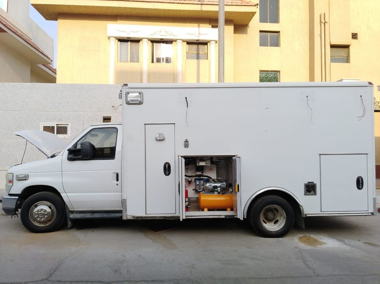
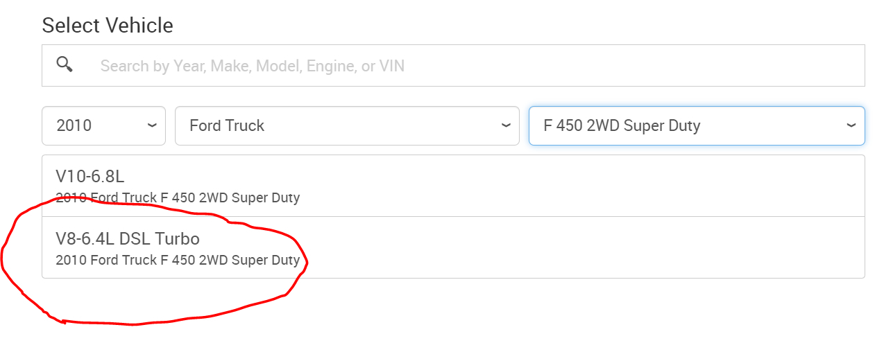
As far as head removal, all I have is for the 6.4. Guess what. I just figured out why I couldn't find it. You listed it as an F450. I believe it is an E450 which offers the 6.0L Diesel.
As far as major repairs, it could be a cracked or damaged cylinder head, block, bent valve, piston damage and so on which can mandate engine replacement. I feel bad not to provide a clear answer, but I don't know what to expect.
Here are the directions for total engine disassembly. It is extensive. I'm including everything. If it is only the heads that need removed, you will stop at that point. All attached pictures correlate with the directions.
________________________________________________
2010 Ford Truck E 450 V8-6.0L DSL Turbo
Engine - Disassembly
Vehicle Engine, Cooling and Exhaust Engine Service and Repair Overhaul Engine - Disassembly
ENGINE - DISASSEMBLY
303-01D Engine — 6.0L Diesel 2010 E-Series
DISASSEMBLY
Engine
Special Tool(s)
pic 1
209-00153 or equivalent
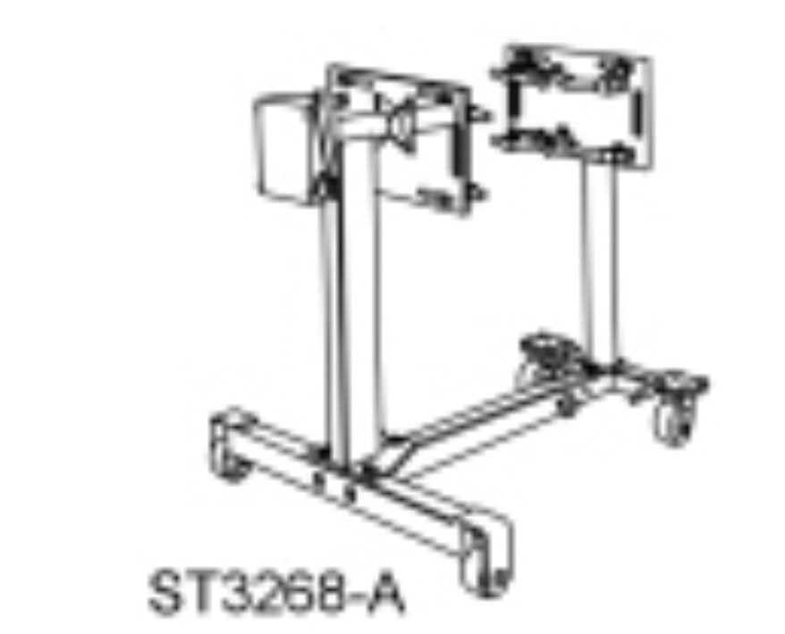
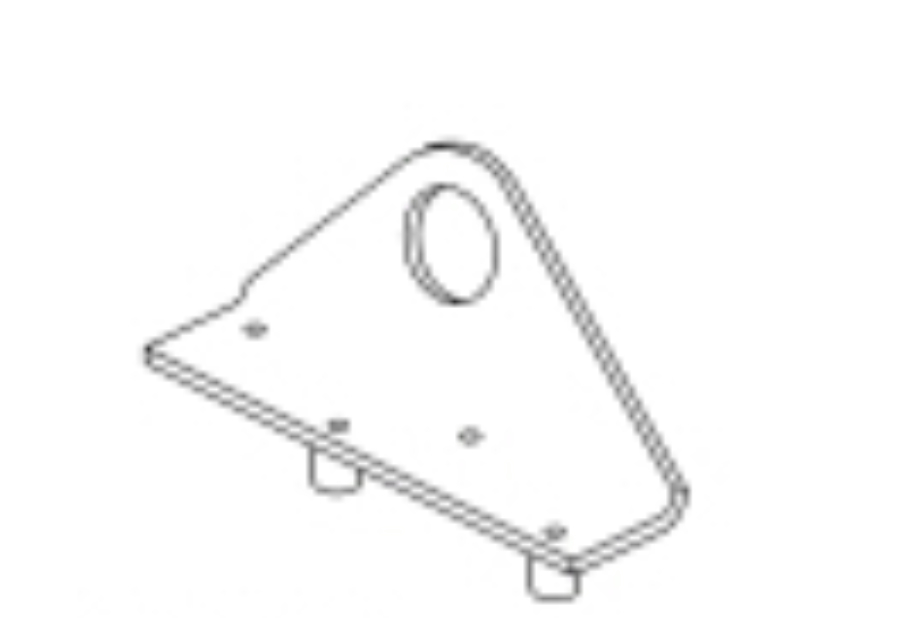
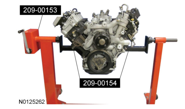
pic 2 6.0 Liter and 6.4 Liter Engine Stand Adapters
209-00154 or equivalent
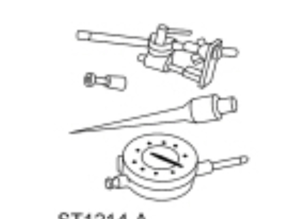
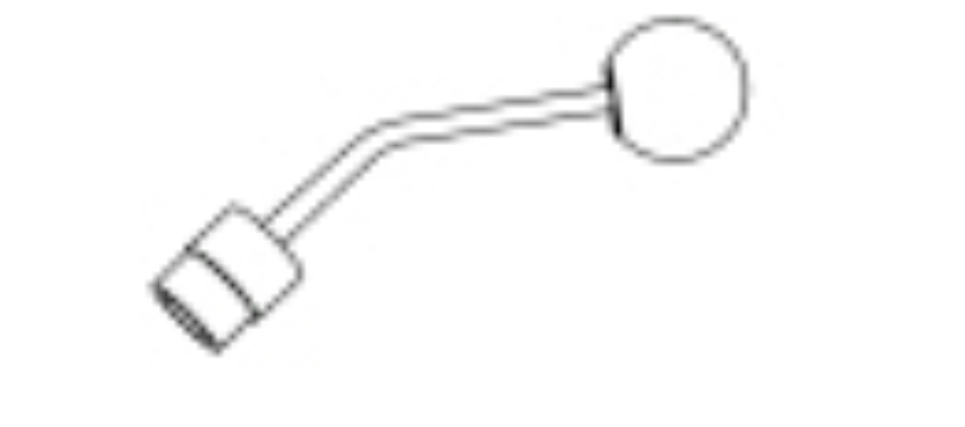
pic 3 Dial Indicator Gauge with Holding Fixture
100-002 (TOOL-4201-C)
pic 4 Feeler Gauge Set
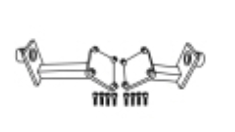
303-D027 (D81L-4201-A) or equivalent
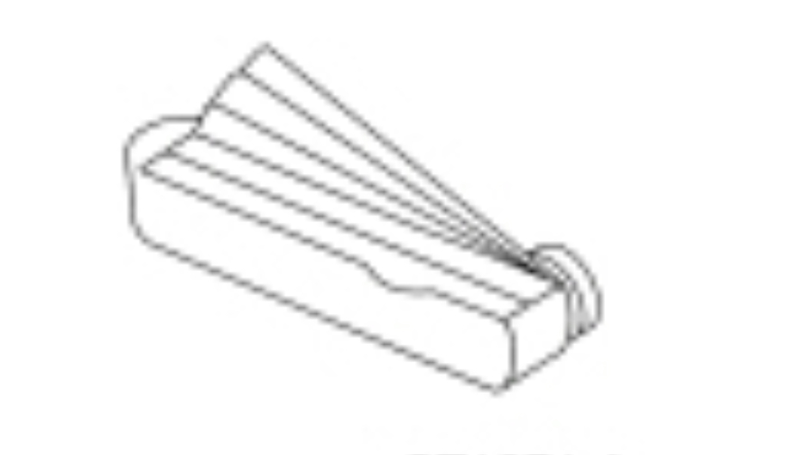
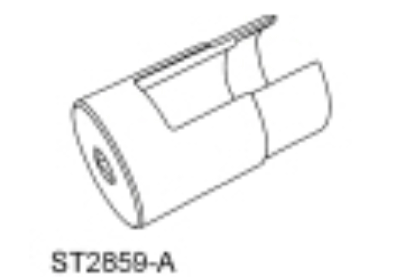
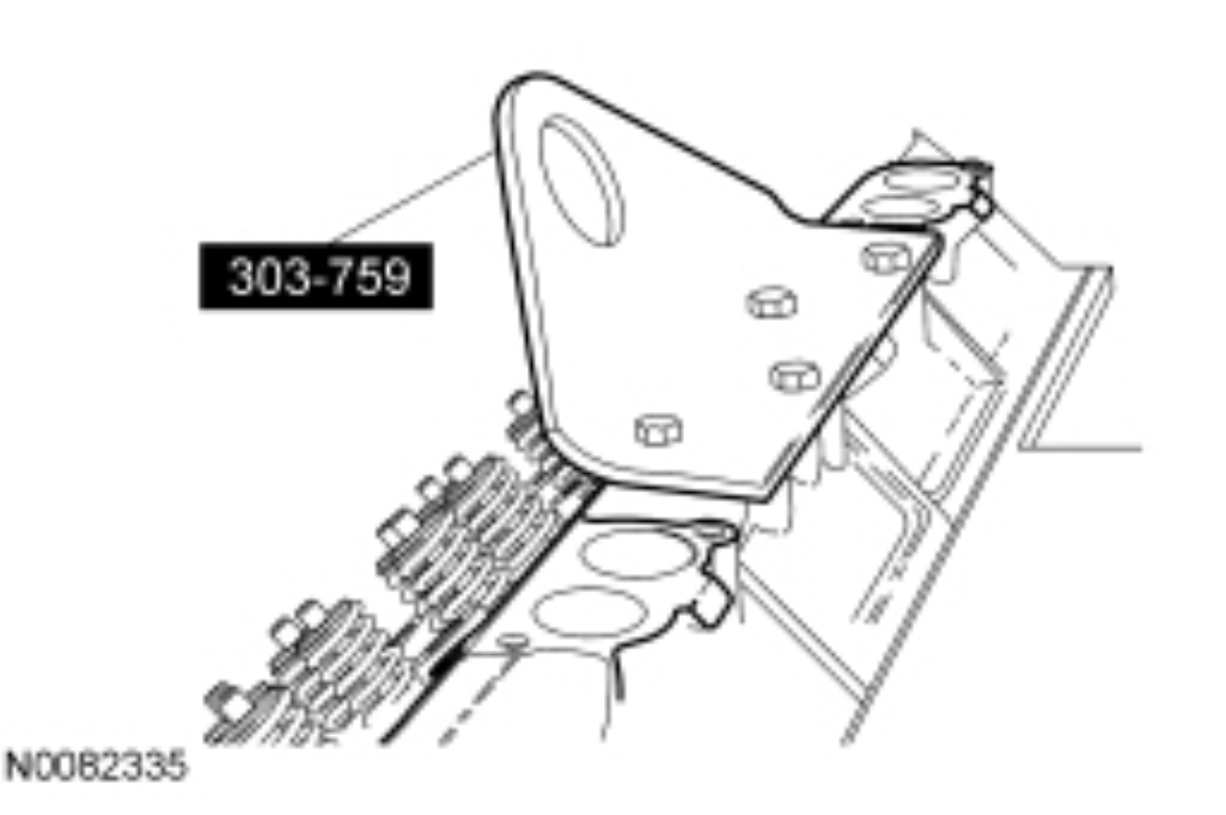
pic 5 Lifting Bracket, Cylinder Head
303-759
pic 6 Release Tool, Injector Connector
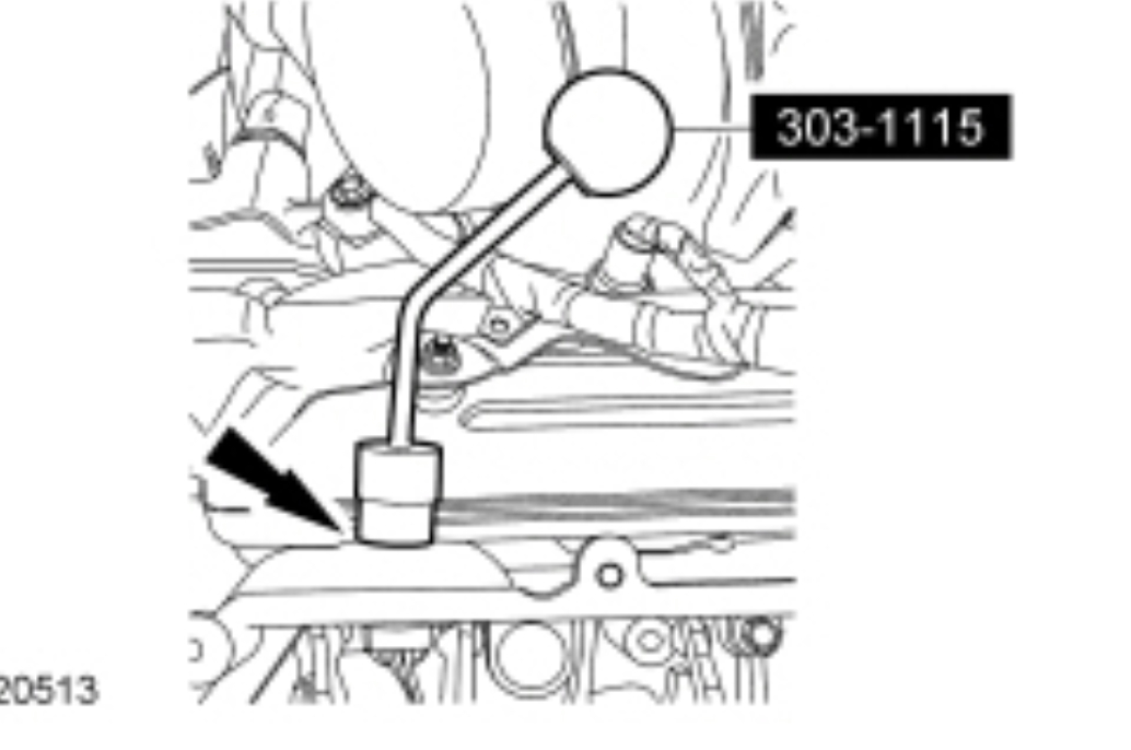
303-1115
pic 7 Remover, Crankshaft Front Wear Ring
303-762
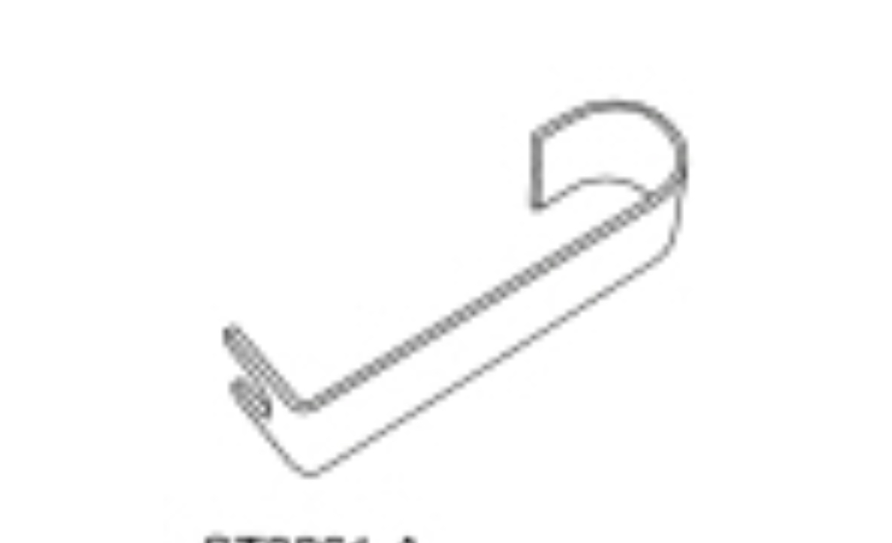
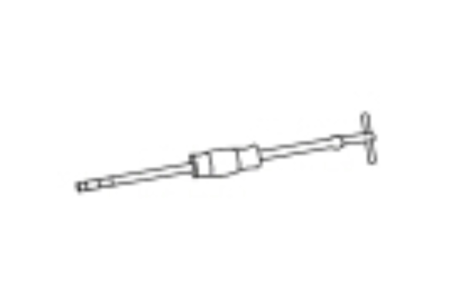
pic 8 Remover, High Pressure Supply Tube
303-1164
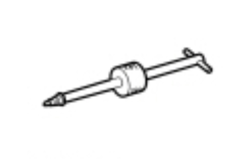
pic 9 Remover/Installer, Glow Plug Connector
303-1114
pic 10 Remover, Oil Seal
303-D060 (D86T-6701-B) or equivalent
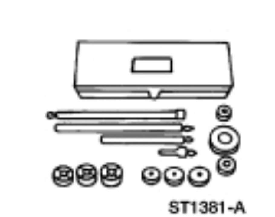
pic 11 Service Set, Camshaft
303-017 (T65L-6250-A) or equivalent
pic 12 Slide Hammer
100-001 (T50T-100-A)
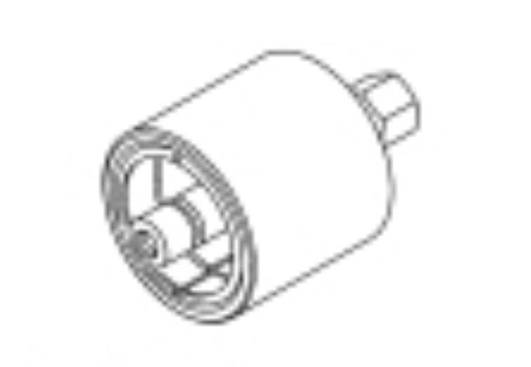
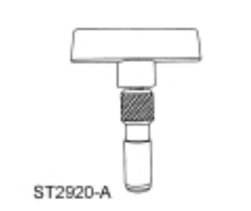
pic 13 Socket, Injection Pressure Regulator
303-1112
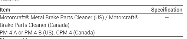
Material
Item Specification
Motorcraft® Metal Brake Parts Cleaner (US) / Motorcraft® Brake Parts Cleaner (Canada)
PM-4-A or PM-4-B (US); CPM-4 (Canada) —
Disassembly
NOTE: For additional information, refer to the exploded view under the Assembly procedure in this section.
Remove the engine. For additional information, refer to Engine in this section.
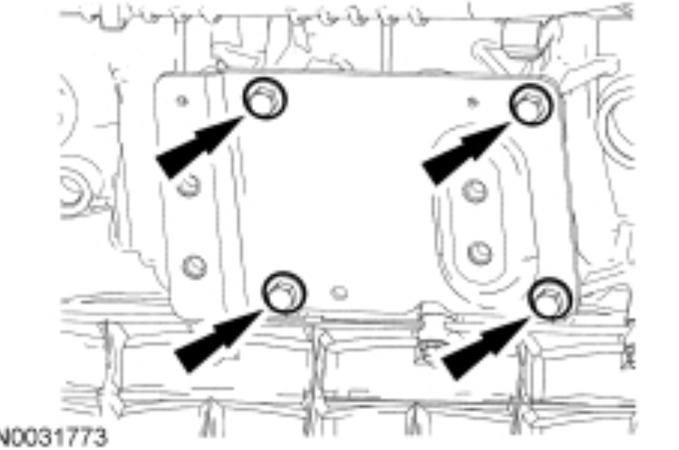
NOTE: RH shown, LH similar.
Remove the 8 bolts and the motor mount brackets.
pic 14
Mount the engine on the 2000 LB. Engine Stand with the 6.0 Liter and 6.4 Liter Engine Stand Adapters.
pic 15
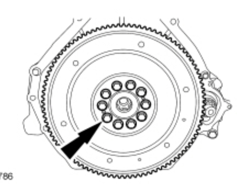
Remove the 10 bolts and the flexplate.
Discard the bolts.
pic 16
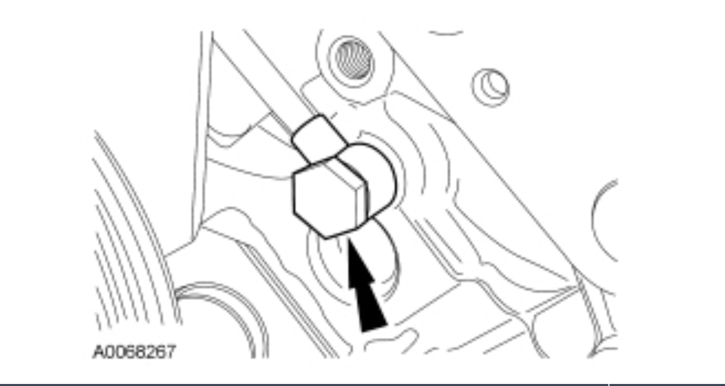
Remove the nut and position the fuel tube support bracket aside.
pic 17
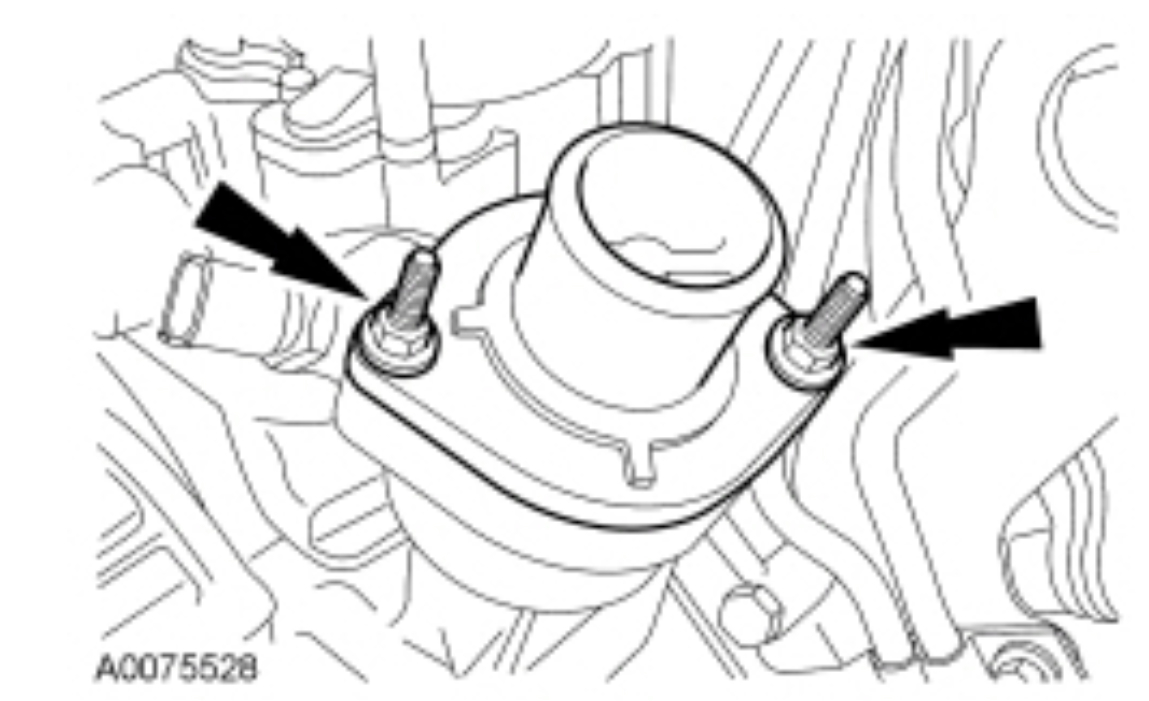
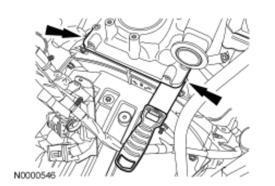
Remove the 2 stud bolts and thermostat housing.
Remove and discard the O-ring seal.
pic 18
Remove the LH cylinder head banjo bolt and fuel tube.
Discard the sealing washers.
pic 19
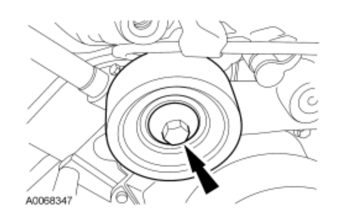
Remove the bolt and the accessory drive belt idler pulley.
pic 20
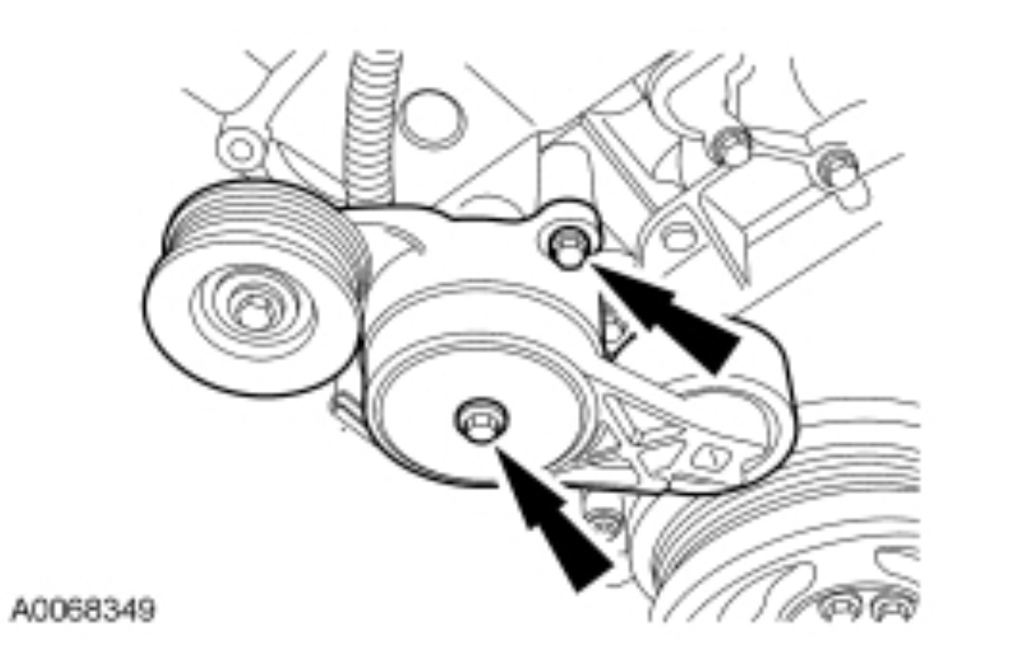
If equipped, remove the 2 bolts and serpentine belt tensioner.
Pic 21
Remove the 4 bolts and oil filter adapter.
pic 22
Remove and discard the O-ring seals from the oil filter base.
pic 23
NOTICE: In the event of a catastrophic engine failure, always install a new oil cooler. Foreign material cannot be removed from the oil cooler and engine damage may occur.
Remove the 10 bolts and the oil cooler assembly.
pic 24
If necessary, replace the oil cooler. For additional information, refer to Oil Cooler in the disassembly and assembly of subassemblies portion of this section.
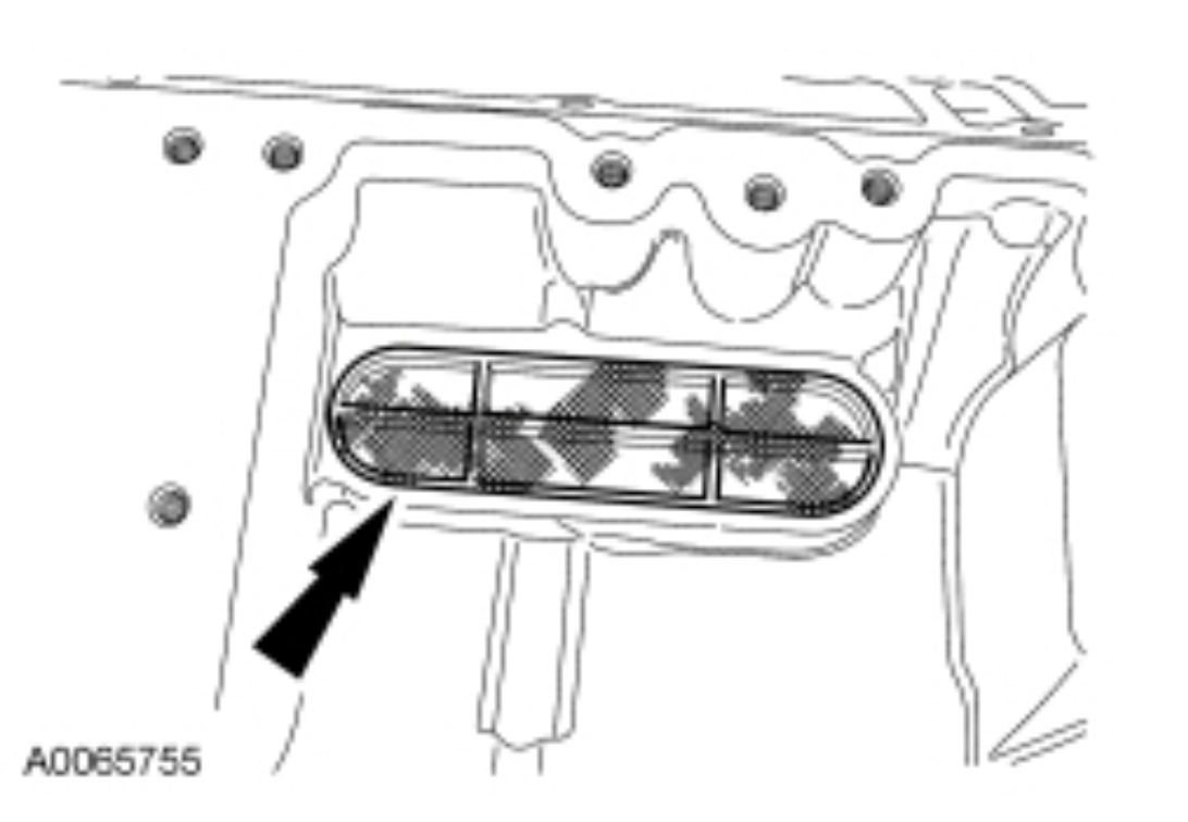
Remove the oil pump inlet strainer.
Clean and inspect for tears and other damage.
pic 25
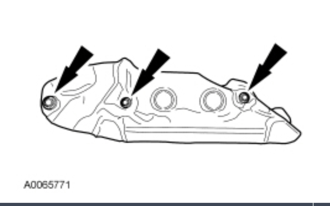
Remove the 3 bolts and the turbocharger heat shield.
pic 26
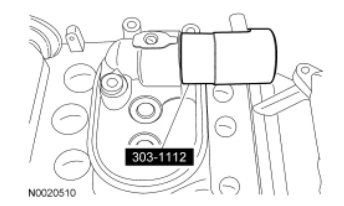
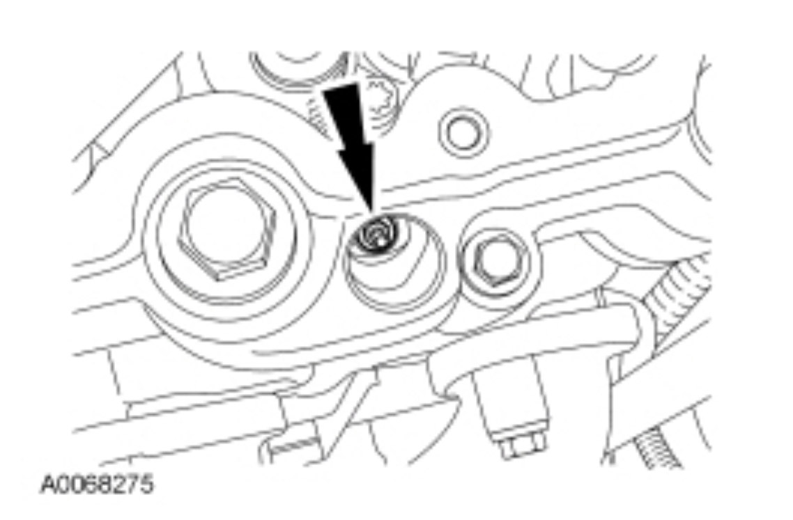
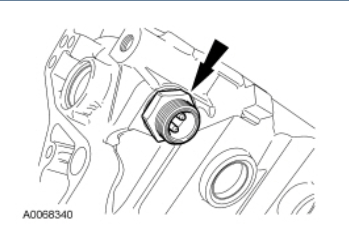
Using the Injection Pressure Regulator Socket, remove the Injection Pressure Regulator (IPR) valve.
pic 27
Remove the 8 bolts from the high-pressure oil pump cover.
pic 28
NOTE: To prevent engine damage, do not pry the high-pressure pump cover from the pump or damage to the cover can occur.
Use a thin gasket scraper to separate the cover from the crankcase at the rear cover seam. Remove the high-pressure oil pump cover.
Remove and discard the press-in-place gasket.
pic 29
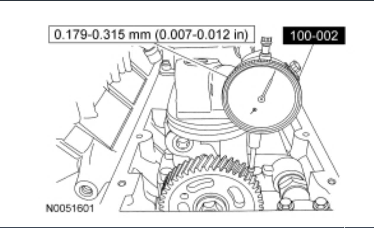
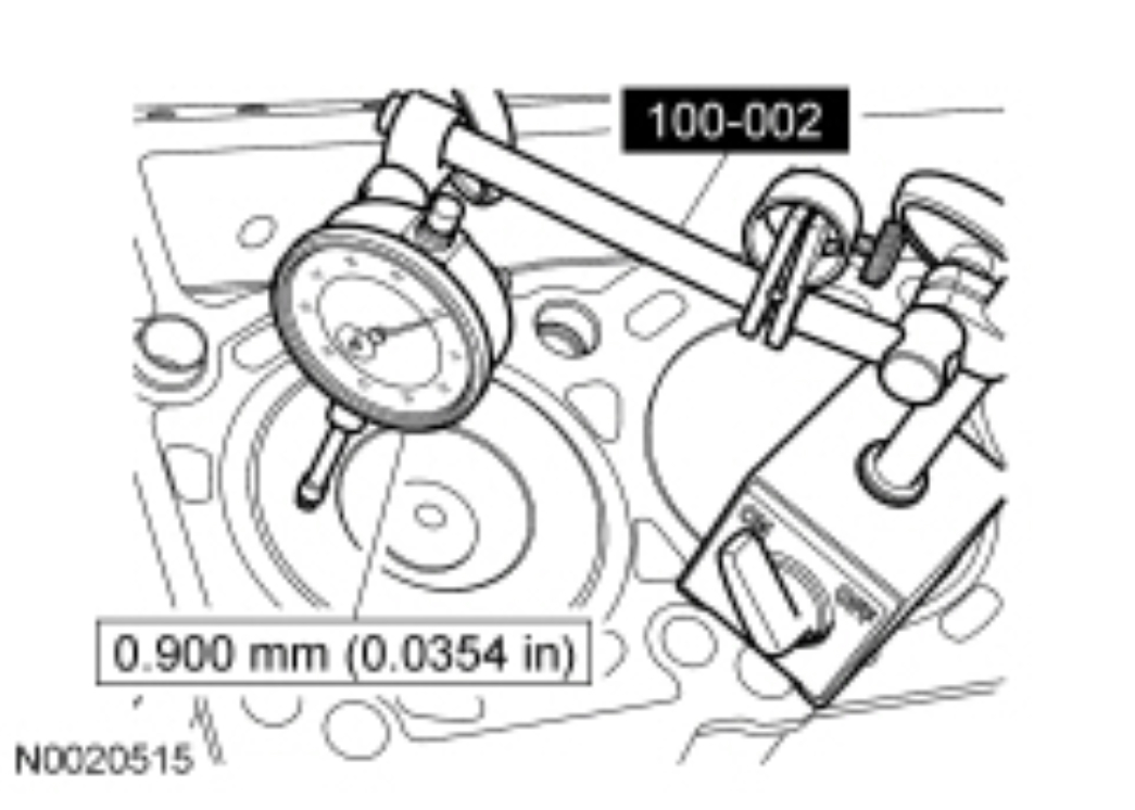
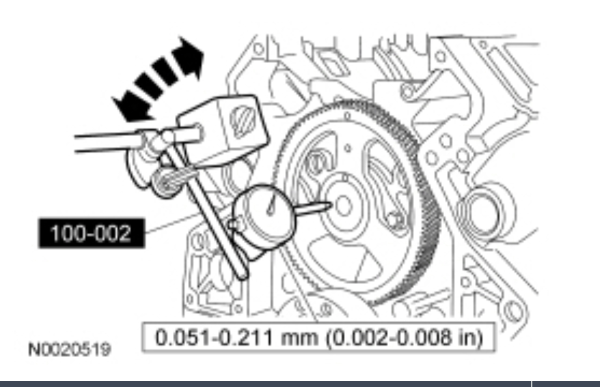
Position the Dial Indicator Gauge with Holding Fixture and check the oil pump drive gear backlash.
pic 30
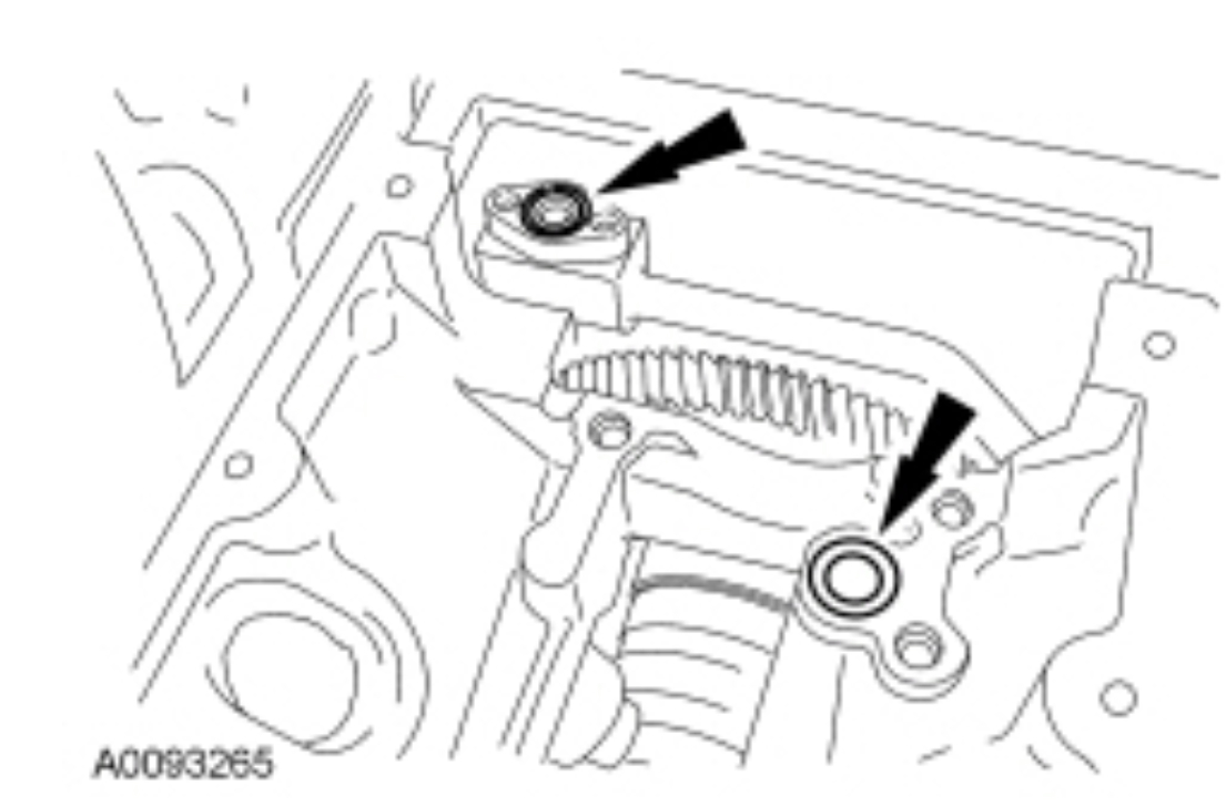
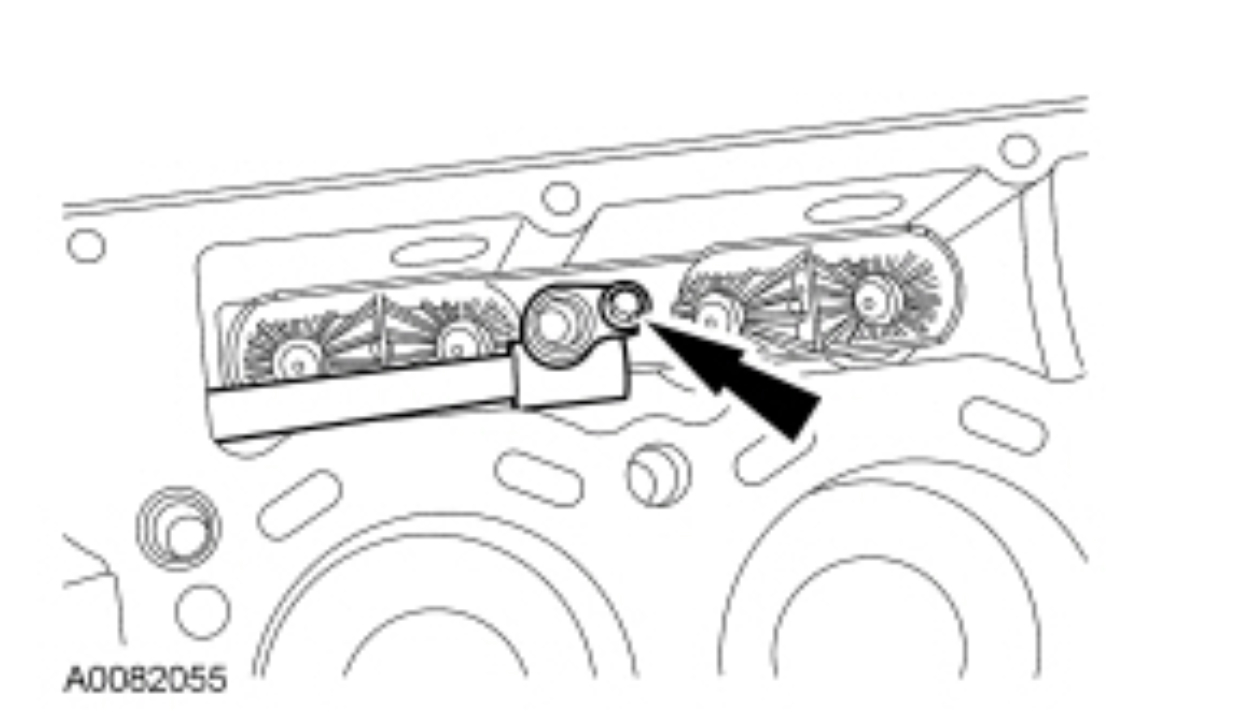
Remove the bolts on the high-pressure oil branch tube adapter.
pic 31
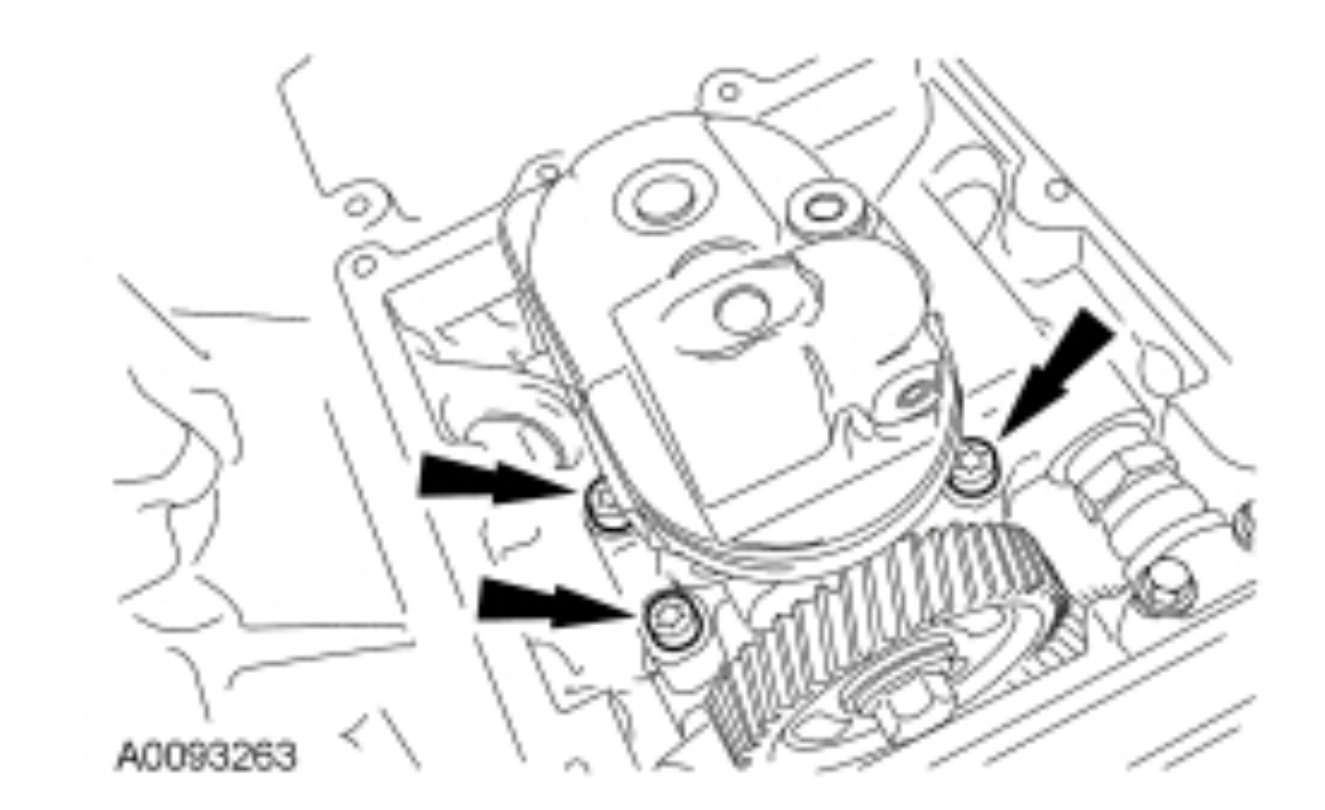
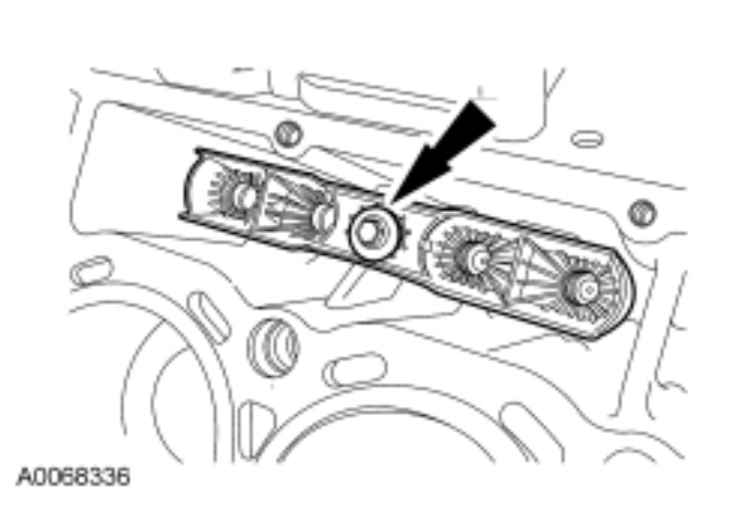
Remove the bolts and the high-pressure oil pump.
pic 32
Remove and discard the lower O-ring seals.
pic 33
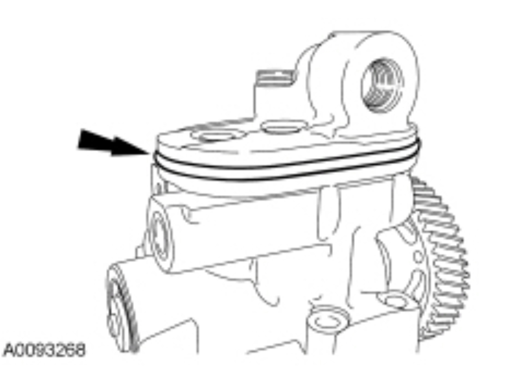
Remove and discard the high-pressure oil pump O-ring seal.
pic 34
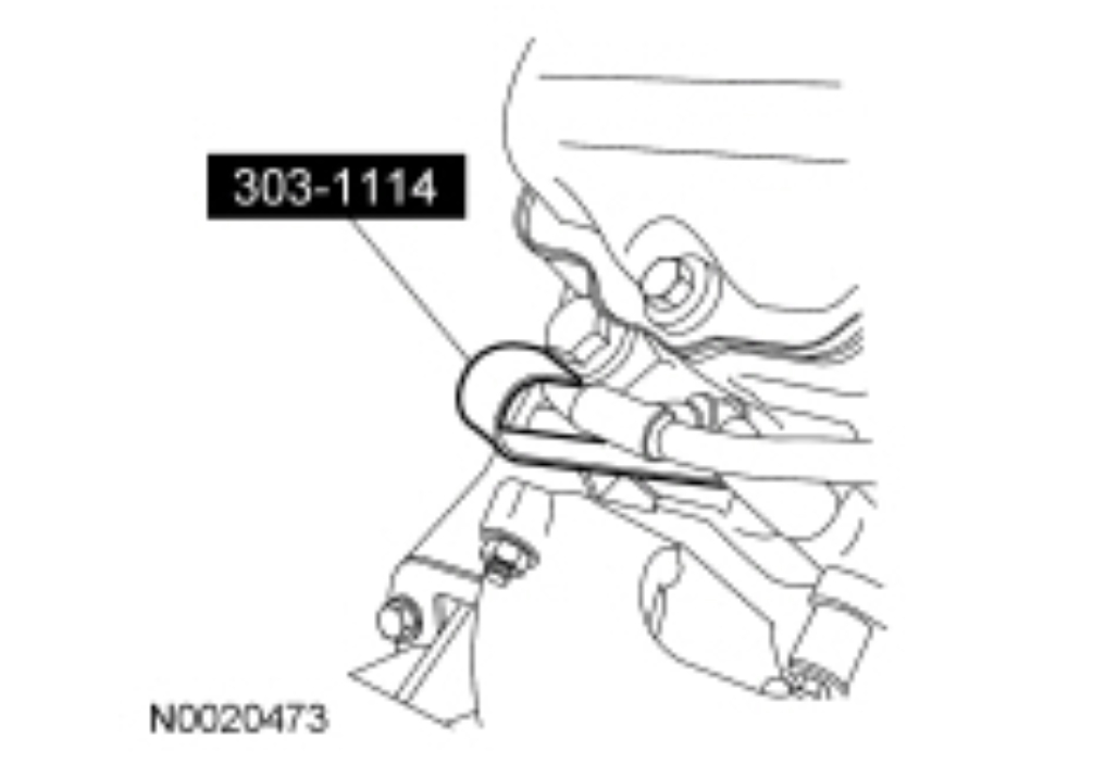
NOTICE: Do not pull on the wiring to remove the glow plug connector or damage may occur.
Using the Glow Plug Connector Remover/Installer, remove the glow plug harness.
pic 35
Remove the 8 glow plugs.
pic 36
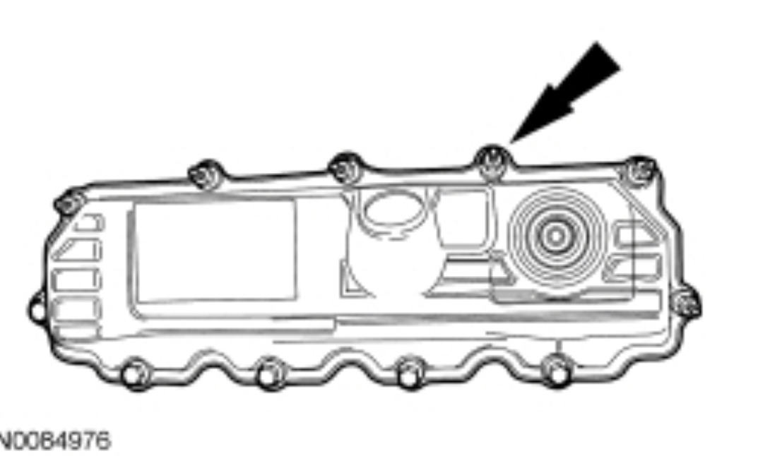
Remove the protective covering from the LH cylinder head.
NOTE: Mark the location of the stud bolts.
Remove the 6 stud bolts, 5 bolts and the RH valve cover.
Clean and inspect the gaskets. Install a new gasket, if necessary.
Clean and inspect the sealing surfaces.
pic 37
Remove the high-pressure oil rail-to-valve cover gasket.
pic 38
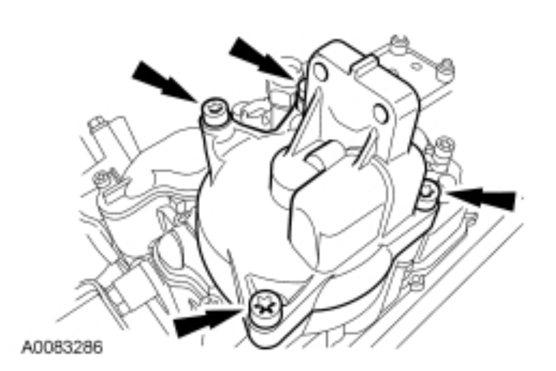
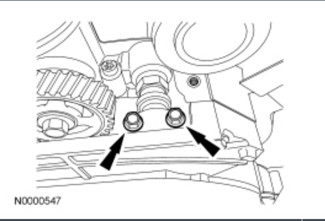
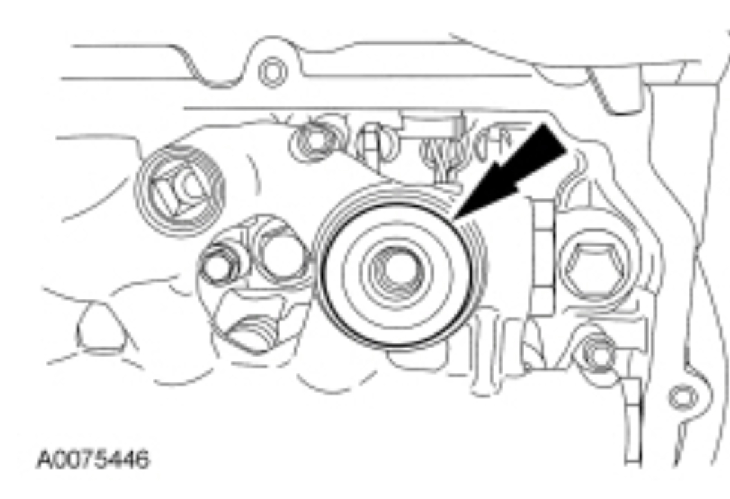
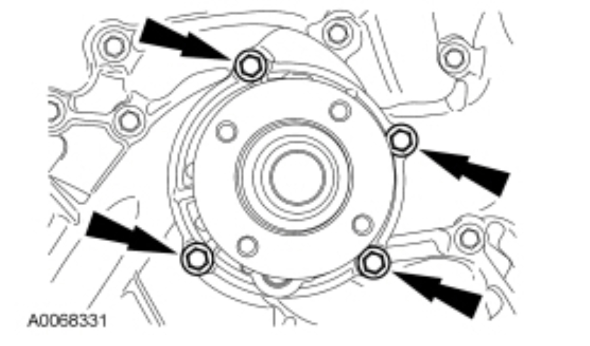
Remove the 4 bolts and the coolant pump pulley.
pic 39
Remove the 4 bolts and the coolant pump.
Discard the O-ring seal.
pic 40
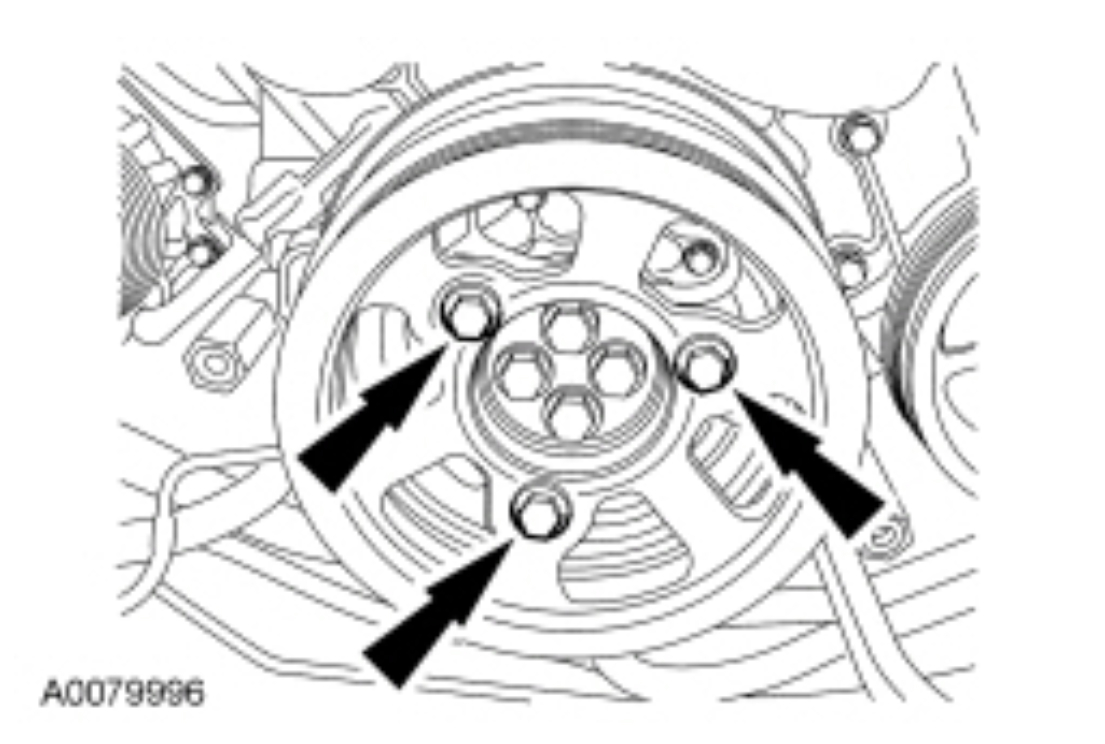
If equipped, remove the 3 bolts and the dual generator pulley.
pic 41
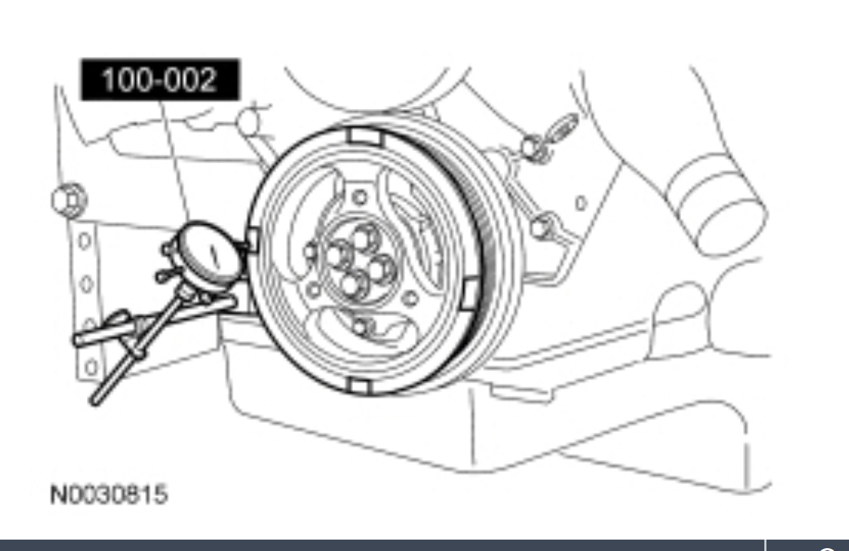
Check the crankshaft vibration damper runout.
Remove the paint from the face of the crankshaft vibration damper at 4 points, 90 degrees apart.
Attach the Dial Indicator Gauge with Holding Fixture to the cylinder block. Position the Dial Indicator Gauge with Holding Fixture on one of the unpainted surfaces.
Using a suitable tool, pry the crankshaft forward. Zero the Dial Indicator.
NOTE: Pry the crankshaft forward at the same point to eliminate possible error caused by crankshaft end play.
Rotate the crankshaft 90 degrees. Pry the crankshaft forward. Record the measurement. Repeat at each unpainted surface.
If the runout exceeds specification, install a new crankshaft vibration damper.
pic 42
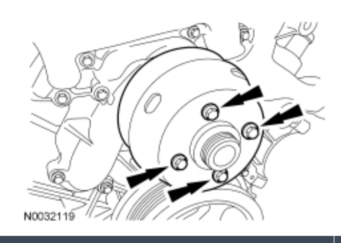
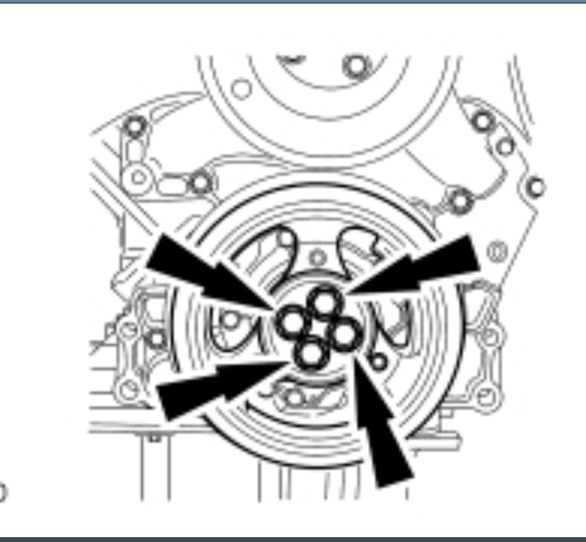
image WARNING: Support the vibration damper during mounting bolt removal. The damper can slide off the nose of the crankshaft. Failure to follow this instruction may result in serious personal injury.
NOTICE: To prevent engine damage, always install new bolts when installing the vibration damper.
Remove the 4 bolts and the crankcase vibration damper.
Discard the bolts.
pic 43
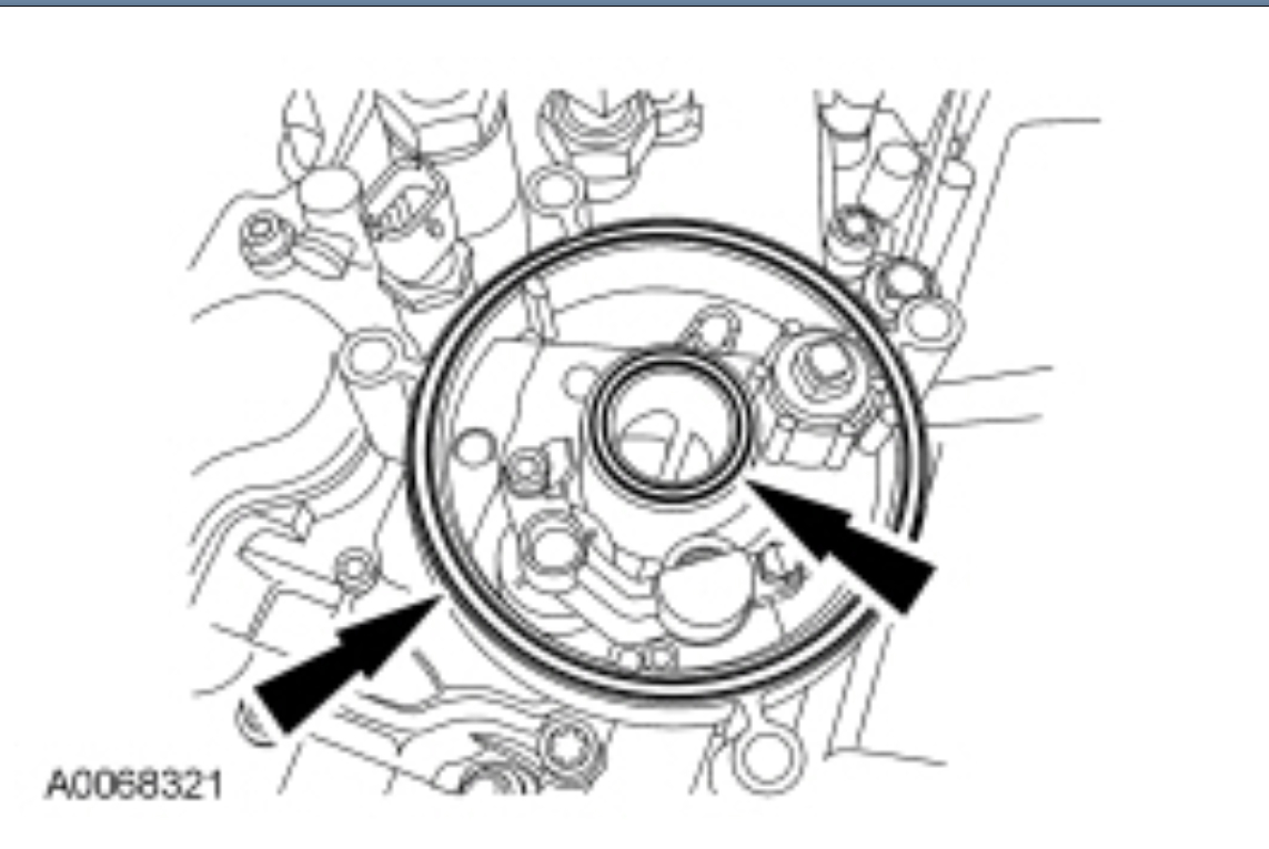
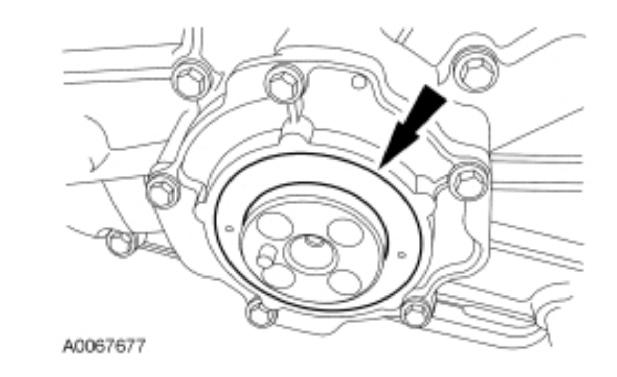
Punch 2 holes in the crankshaft front seal.
pic 44
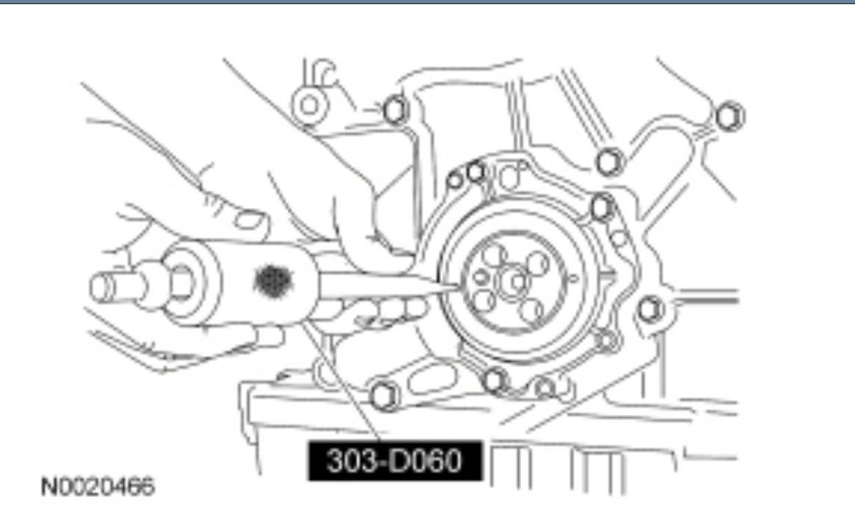
Using the Oil Seal Remover, remove the crankshaft front seal.
Discard the seal.
pic 45
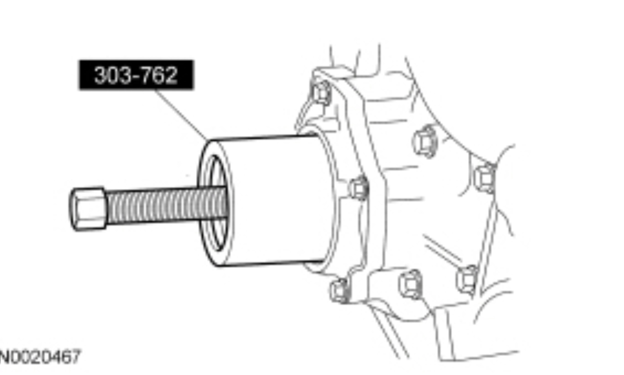
NOTE: Production seals will not have a wear sleeve. If a service part has been installed, it will have a wear sleeve.
If equipped, remove and discard the crankshaft seal wear sleeve with the Crankshaft Front Wear Ring Remover.
pic 46
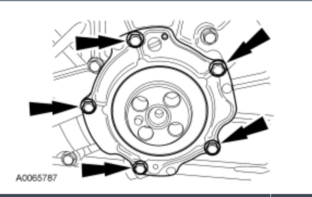
Remove the 5 bolts and the oil pump body.
Discard the O-ring seal.
pic 47
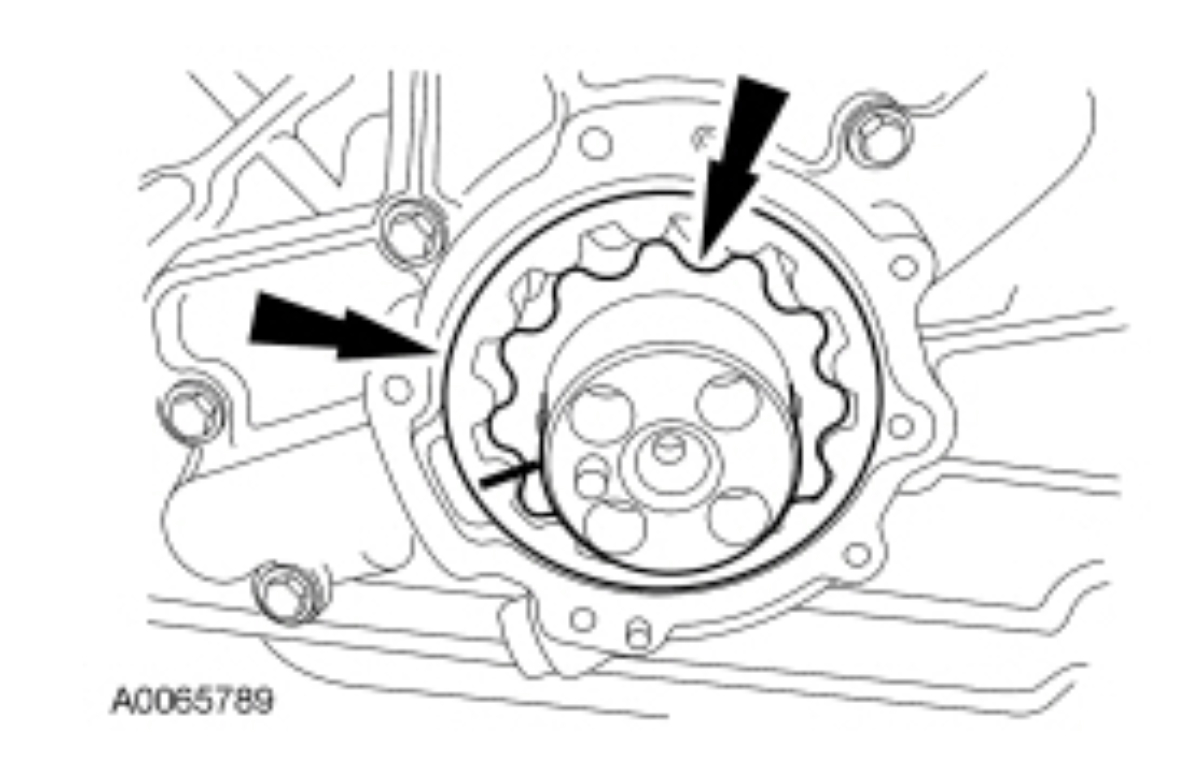
NOTE: Mark the front of each drive rotor for correct reassembly orientation.
Remove the inner and outer oil pump drive rotors.
pic 48
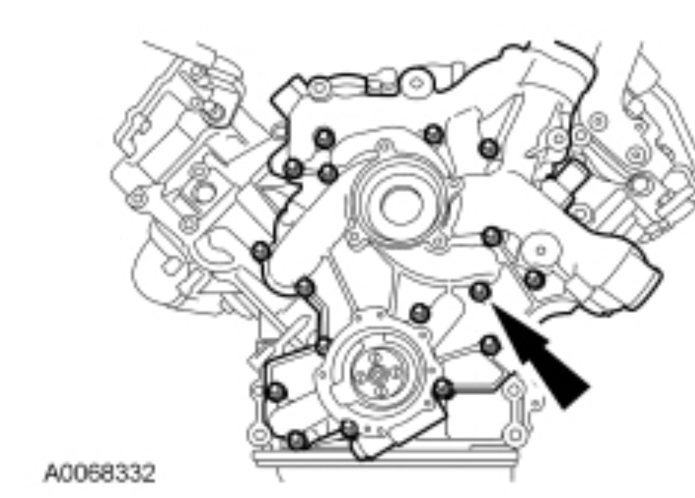
Remove the 17 bolts and engine front cover.
pic 49
NOTICE: Sealant is used where the crankcase and lower crankcase meet. Failure to cut the sealant may result in pulling the lower crankcase seal out and damaging it while removing the front cover gasket.
Use a thin-blade scraper to cut the sealant where the crankcase and the lower crankcase meet. Remove and discard the front cover gasket.
NOTICE: Use extreme care when removing the flywheel front adapter to prevent damage to the alignment dowel pin.
Remove the flywheel front adapter.
pic 50
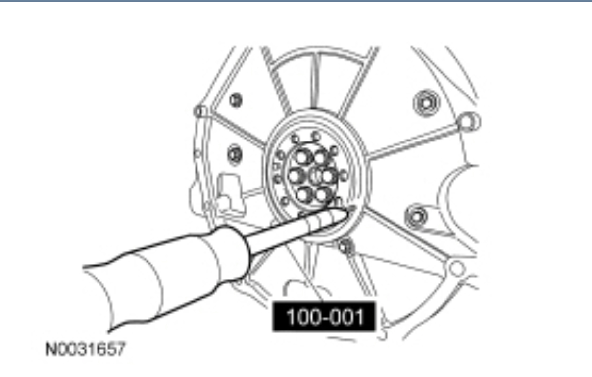
NOTICE: To prevent engine damage, do not remove the rear primary crankshaft flange bolts under any circumstances. If the flange is removed and reinstalled, it will result in engine vibration and premature transmission component wear.
NOTICE: Drill only deep enough to penetrate the seal. Engine damage will occur if the seal is drilled too deep.
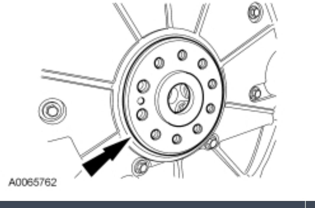
Using a center punch, mark a location for 2 holes 180 degrees apart, 9.53 mm (0.37 in) from the outer diameter of the crankshaft flange. Using a drill bit of the appropriate size for the Slide Hammer being used, drill a hole on each side of the crankshaft rear seal as shown. Drill the holes to a depth of 8.76 mm (0.34 in) to capture the metal case of the crankshaft seal as well as the wear ring.
pic 51
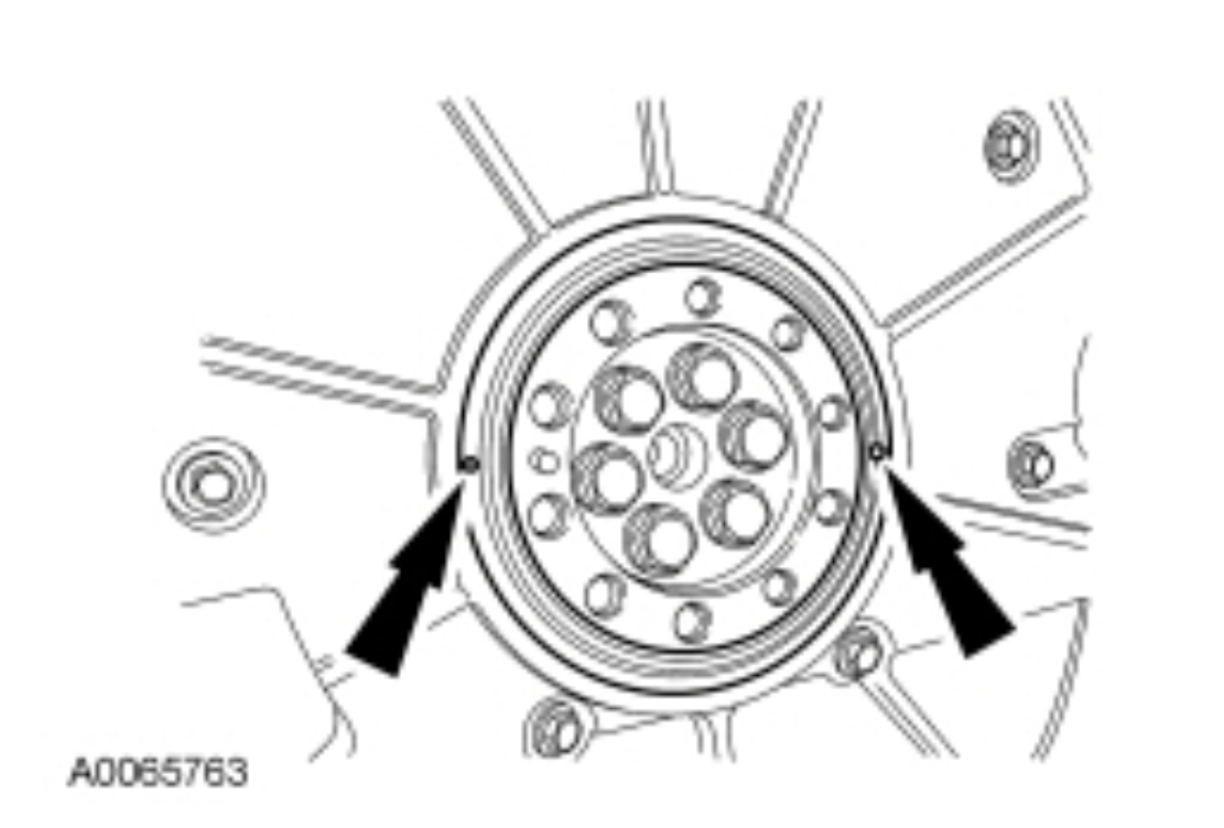
Using the 2 drilled holes, the Slide Hammer and a commercially available body dent puller attachment, walk the seal out of the rear cover by alternating from side to side to remove the crankshaft rear seal.
Discard the crankshaft rear seal.
pic 52
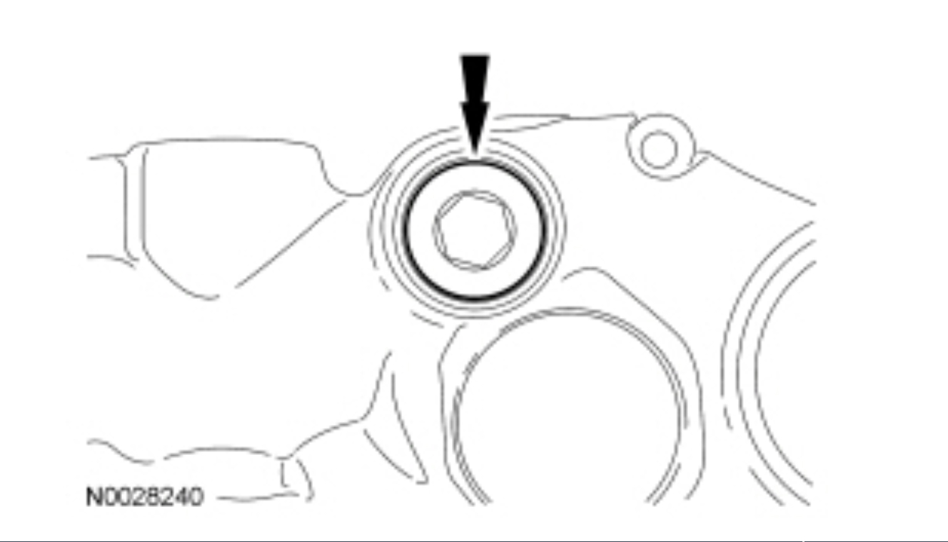
Clean and inspect the crankshaft sealing surface.
pic 53
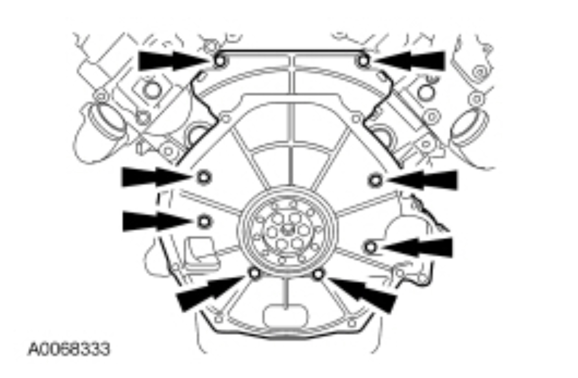
NOTICE: To prevent engine damage, replace damaged or missing dowel pins before installing the engine rear cover.
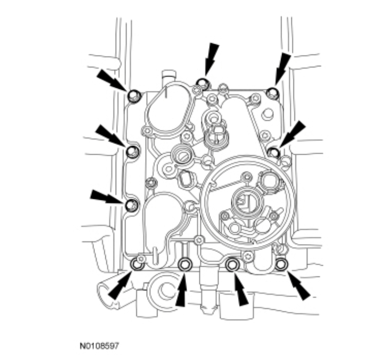
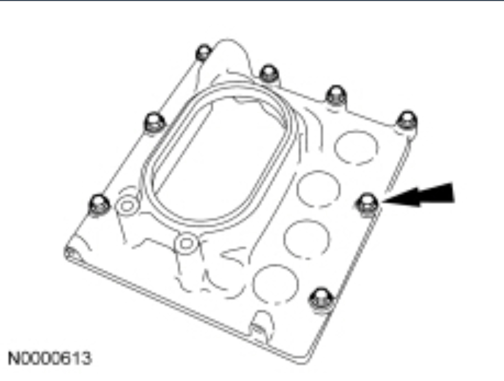
Remove the 8 bolts from the engine rear cover.
pic 54
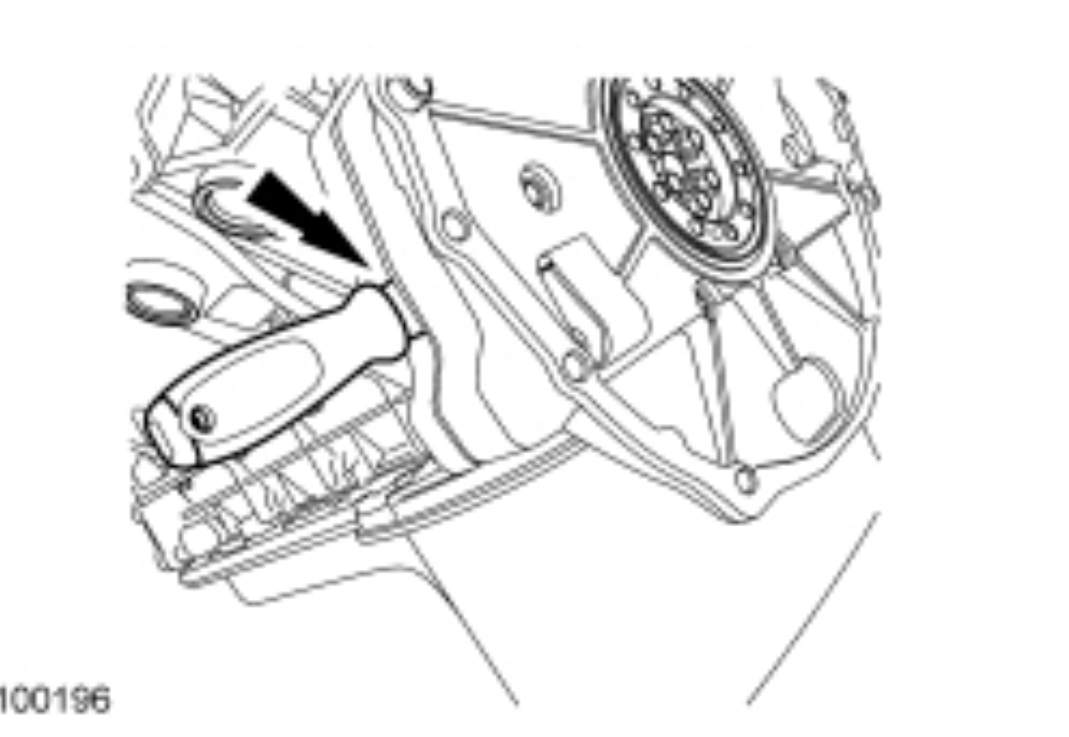
NOTICE: Sealant is used where the crankcase and the lower crankcase meet. Failure to cut the sealant may result in pulling the lower crankcase seal out and damaging it while removing the rear cover.
NOTE: A 139.7 mm (5.5 in) long thin-blade scraper is needed to properly cut the sealant.
Using a thin-blade scraper, cut the sealant where the crankcase and the lower crankcase meet.
pic 55
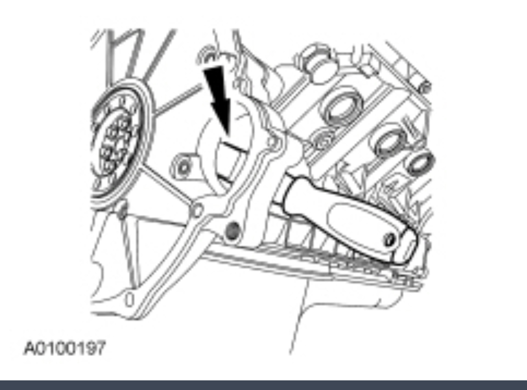
NOTICE: Sealant is used where the crankcase and the lower crankcase meet. Failure to cut the sealant may result in pulling the lower crankcase seal out and damaging it while removing the rear cover.
NOTE: A 139.7 mm (5.5 in) long thin-blade scraper is needed to properly cut the sealant.
Using a thin-blade scraper, cut the sealant where the crankcase and the lower crankcase meet. Remove the engine rear cover.
Remove and discard the press-in-place gasket.
Clean and inspect the sealing surfaces.
pic 56
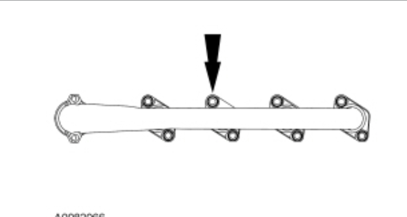
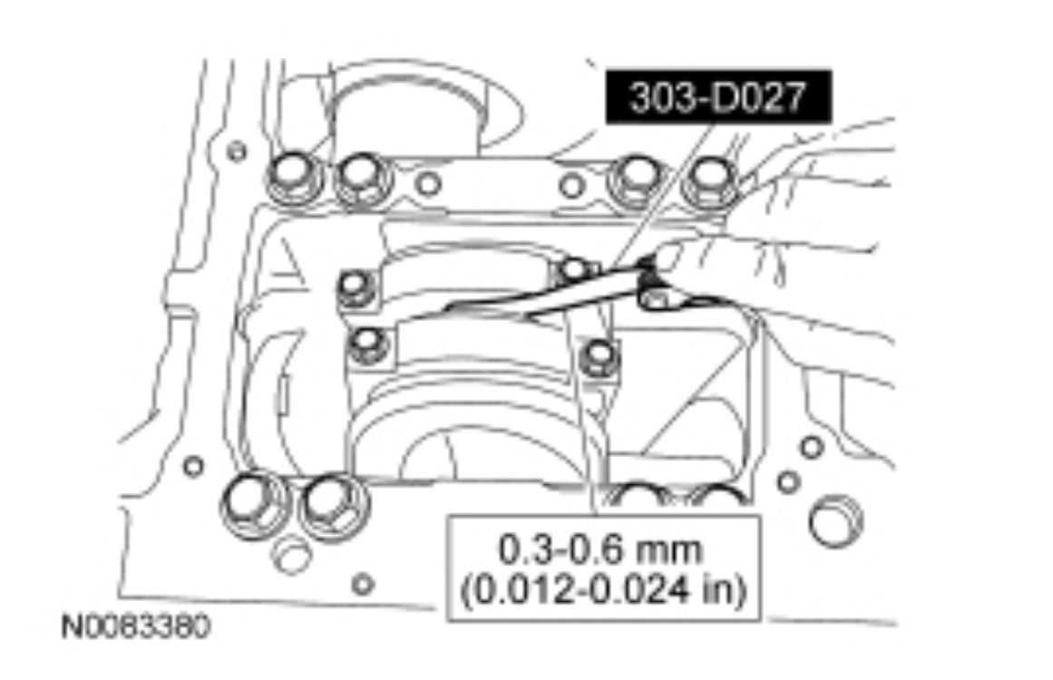
Prior to removing the exhaust manifolds, inspect the exhaust manifolds for warpage with a feeler gauge between the manifold and cylinder head. Record the measurement and compare with the specification.
Remove the 8 bolts, 8 spacers and the RH exhaust manifold.
Discard the bolts.
pic 57
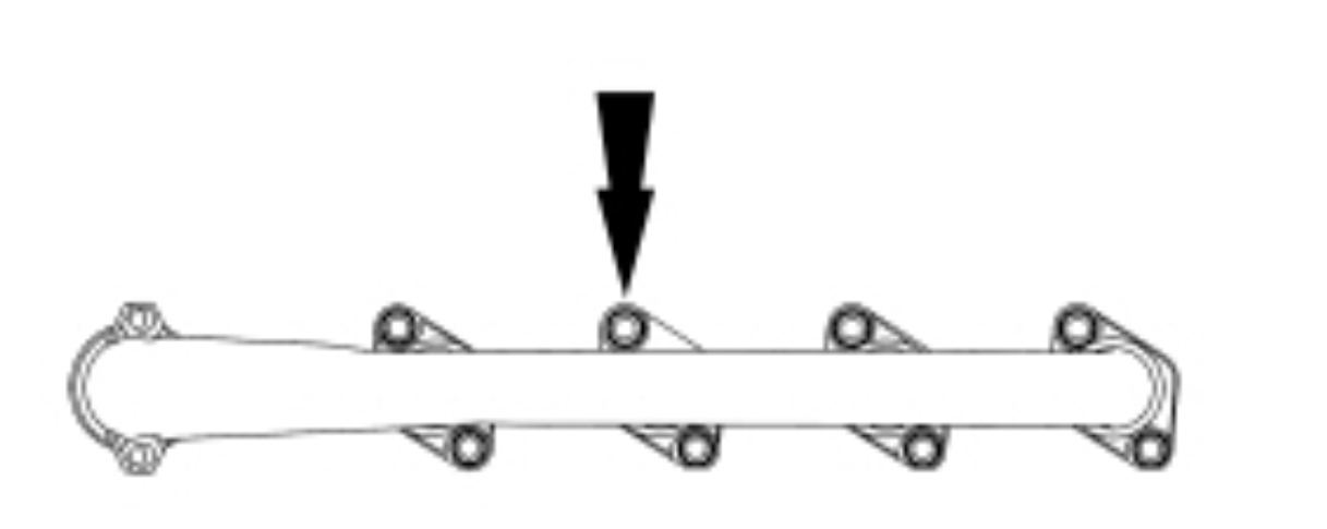
Remove the 8 bolts, 8 spacers and the LH exhaust manifold.
Discard the bolts.
pic 58
Disconnect the fuel injector electrical connectors.
pic 59
Remove the crankcase-to-head tubes.
pic 60
NOTE: Left cylinder head shown, right cylinder head similar.
NOTE: Do not remove the oil rail end plugs or acoustic wave attenuator port fitting. Service parts are not available to support these components.
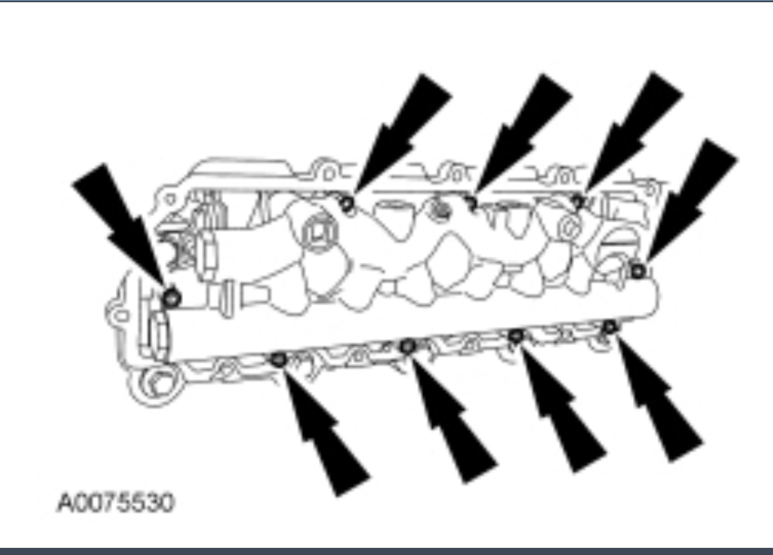
Remove the 18 bolts and the high-pressure oil rails.
pic 61
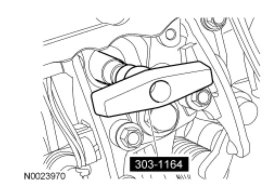
NOTE: Use a shop towel and metal brake parts cleaner to remove the oil residue prior to removing.
If the crankcase-to-head tube separated, using the High Pressure Supply Tube Remover, remove the lower crankcase-to-head tube.
pic 62
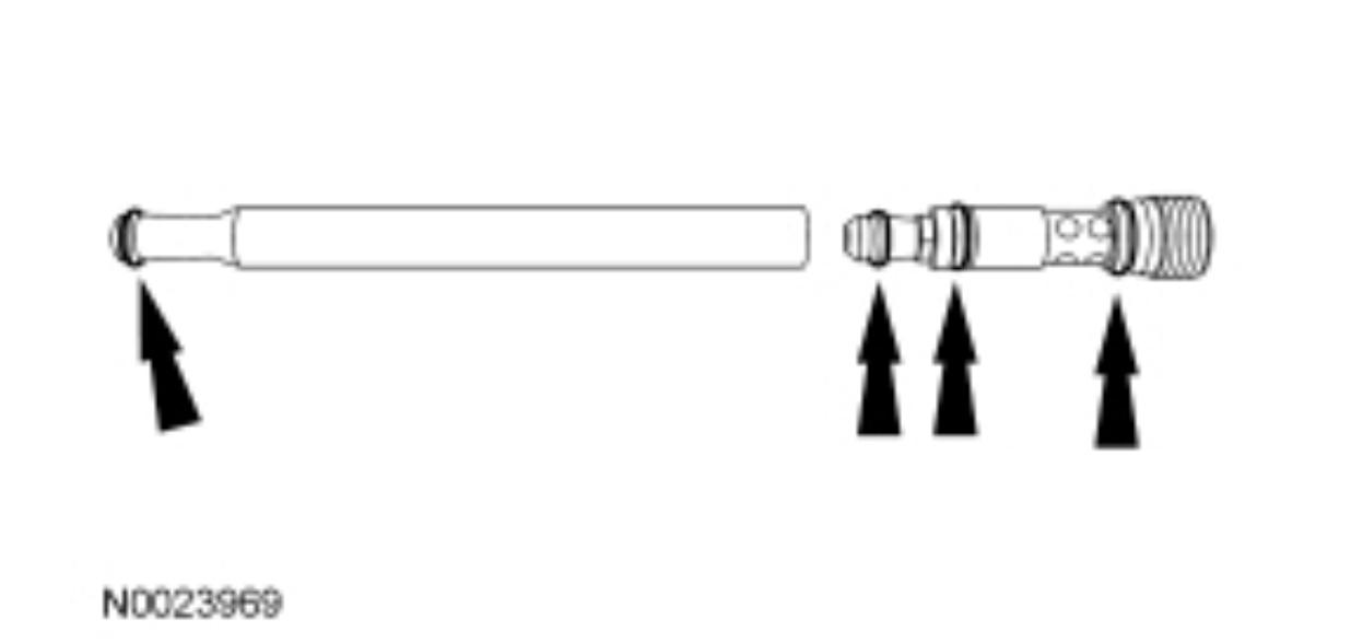
Inspect the D-ring seals for damage (nicks, cuts and gouges). If damaged, replace the crankcase-to-head tube.
pic 63
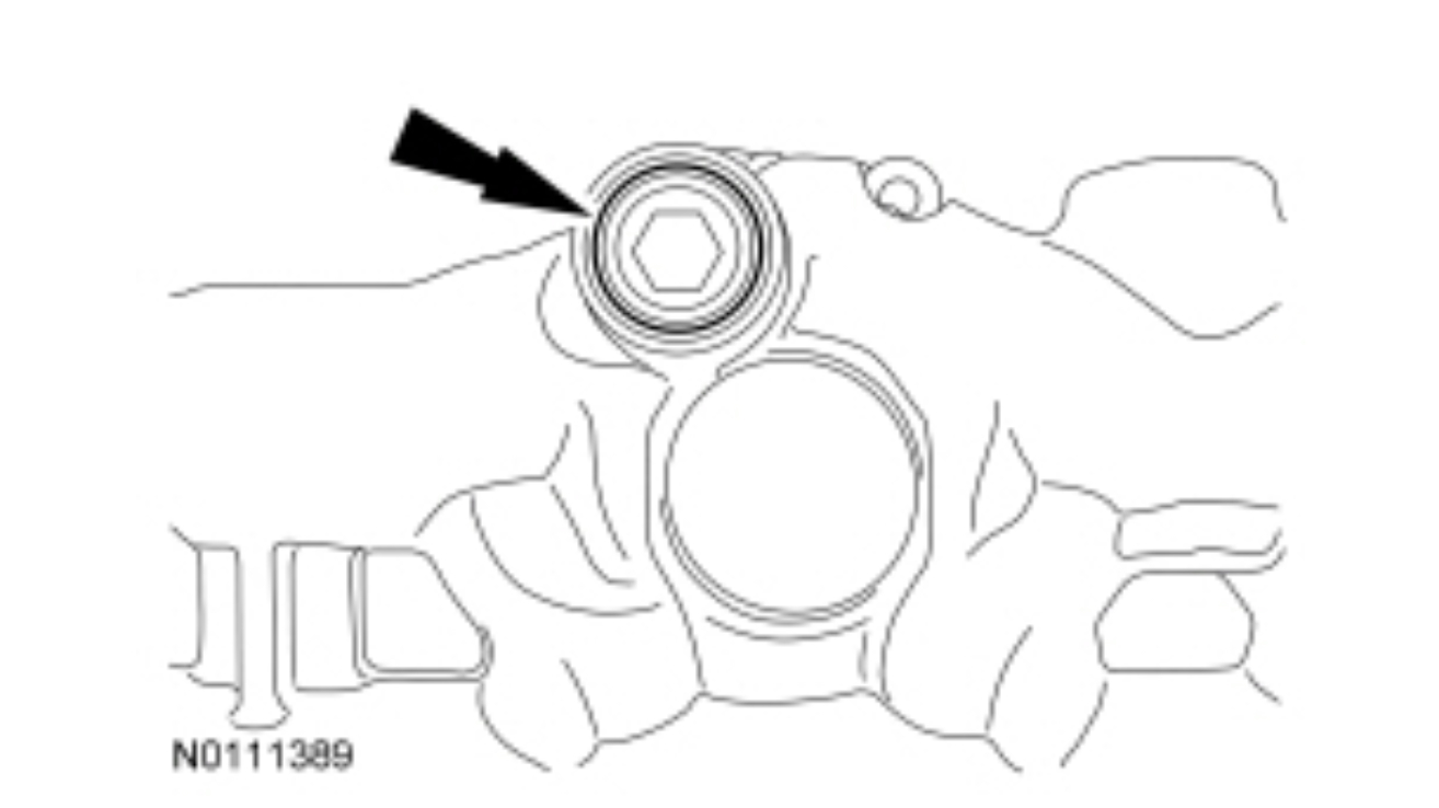
Remove the port plug from the high-pressure oil rail.
Inspect the port plug O-ring seals for damage (nicks, cuts and gouges). If damaged, replace the port plug.
pic 64
NOTICE: Do not attempt to apply battery voltage to the fuel injector or damage to the fuel injector may occur.
Using the Injector Connector Release Tool, push the fuel injector electrical connectors out of the rocker arm carrier.
pic 65
Prior to removing the injector assembly, insert clean shop towels in the oil drain holes adjacent to each glow plug.
NOTICE: To prevent engine damage, do not use air tools when removing and installing the fuel injectors.
NOTE: There is no need to drain the fuel rail.
NOTE: If engine coolant is found in the combustion chambers, it may be necessary to install a new injector sleeve. For additional information, refer to Section 303-04D .
NOTE: The bolt is part of the fuel injector hold-down assembly.
Loosen the bolt and remove the bolt and fuel injector hold-down assembly and the fuel injector.
Remove and discard the O-ring seals and copper washer.
pic 66
Remove the shop towels.
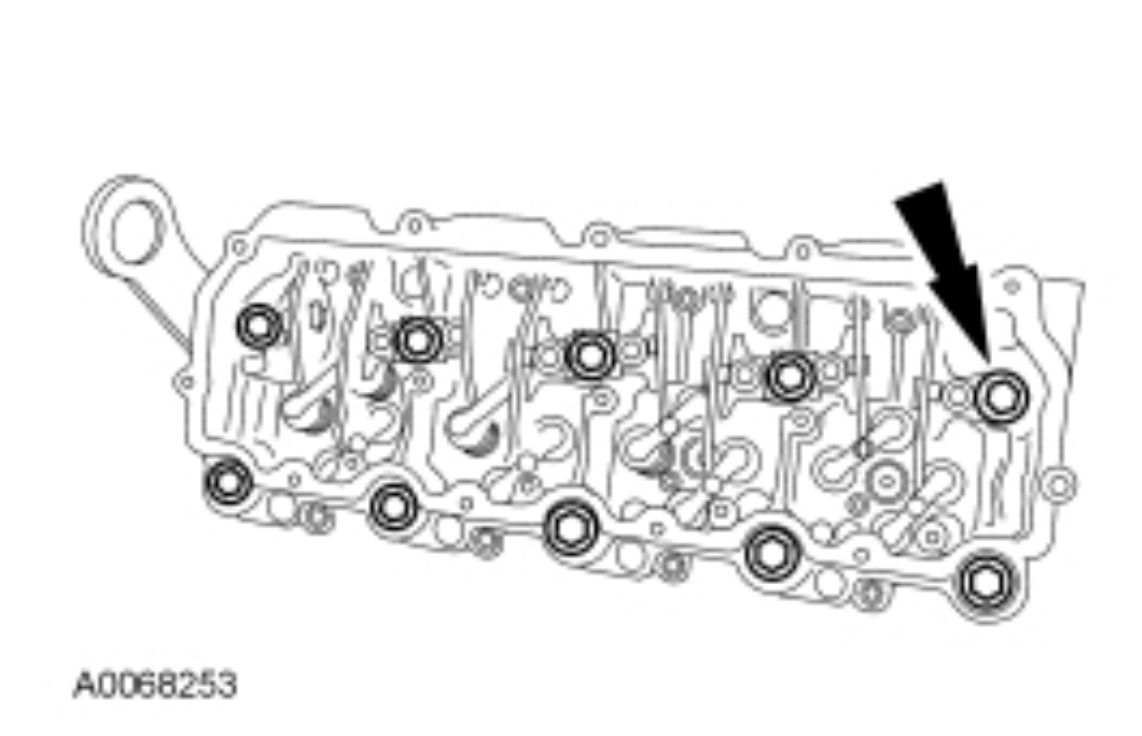
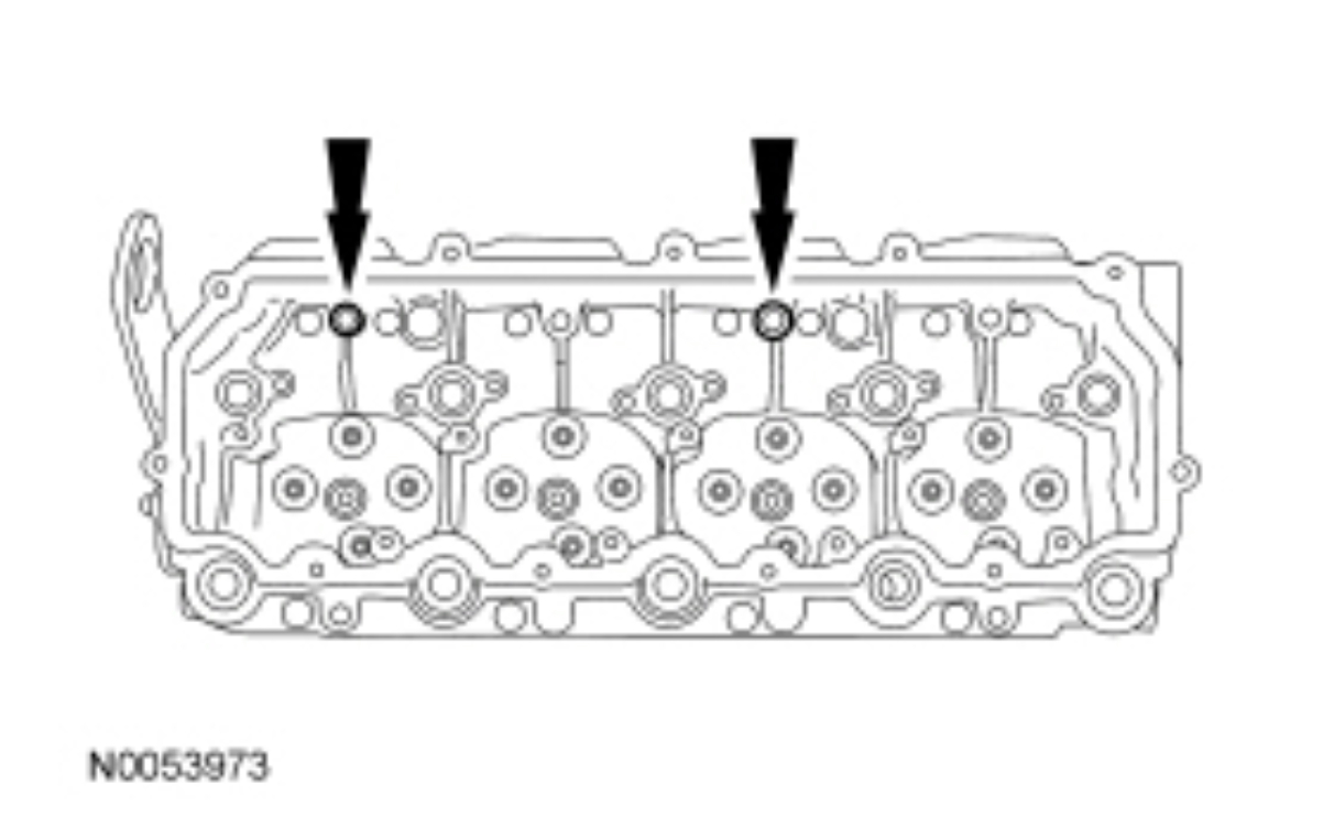
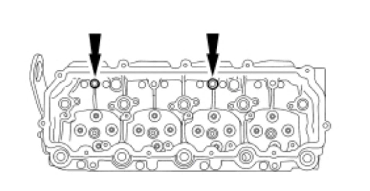
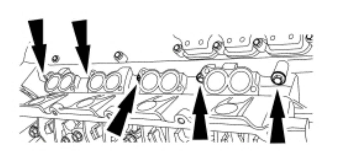
NOTE: Left cylinder head shown, right cylinder head similar.
Remove and discard the 20 head bolts from both cylinder heads.
pic 67
Remove the 16 bolts and the rocker arm assemblies.
pic 68
NOTE: Left cylinder head shown, right cylinder head similar.
Remove the 4 bolts and the rocker arm carriers.
Remove and discard the press-in-place gaskets.
Clean and inspect the sealing surfaces.
pic 69
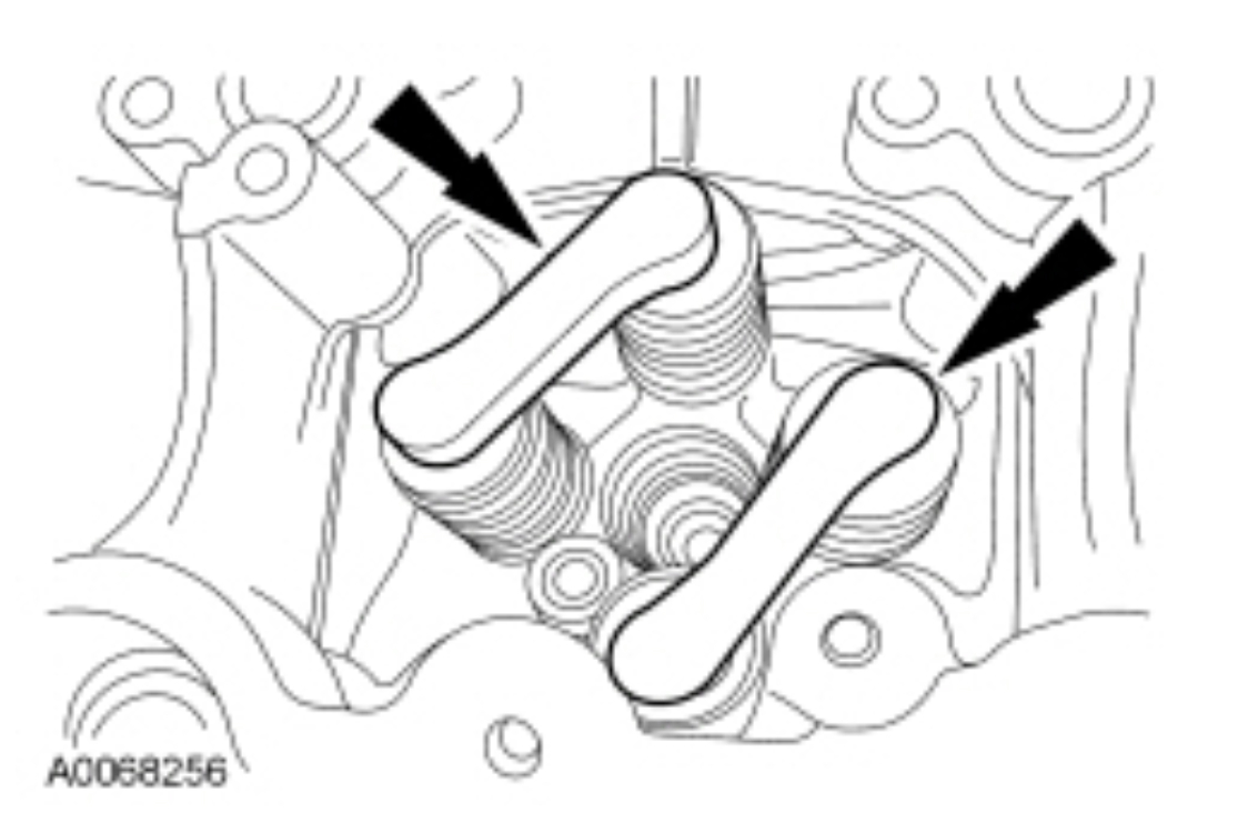
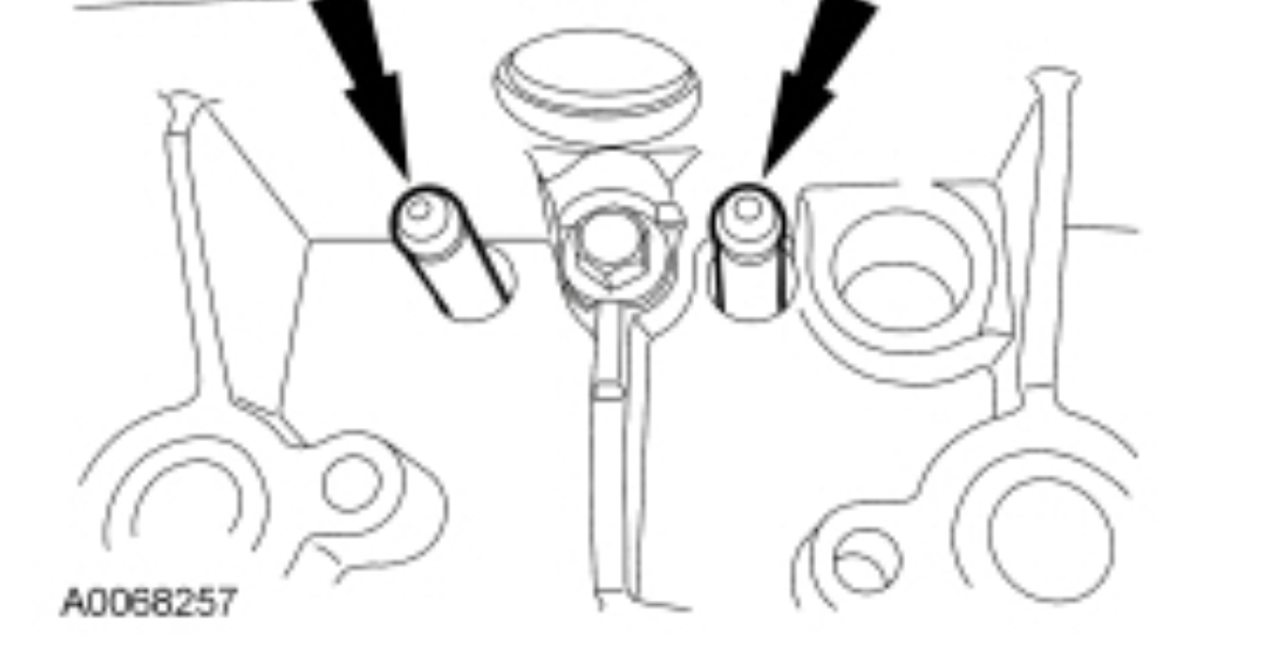
NOTE: Mark the location of the valve bridges before removing.
Remove the 16 valve bridges.
pic 70
NOTICE: To prevent engine damage, keep the push rods in the order in which they were removed. Install all push rods back in their original positions. The push rods are directional and the copper-coated end must be installed in the upward position where it will contact the rocker arm.
Mark and remove the 16 push rods.
pic 71
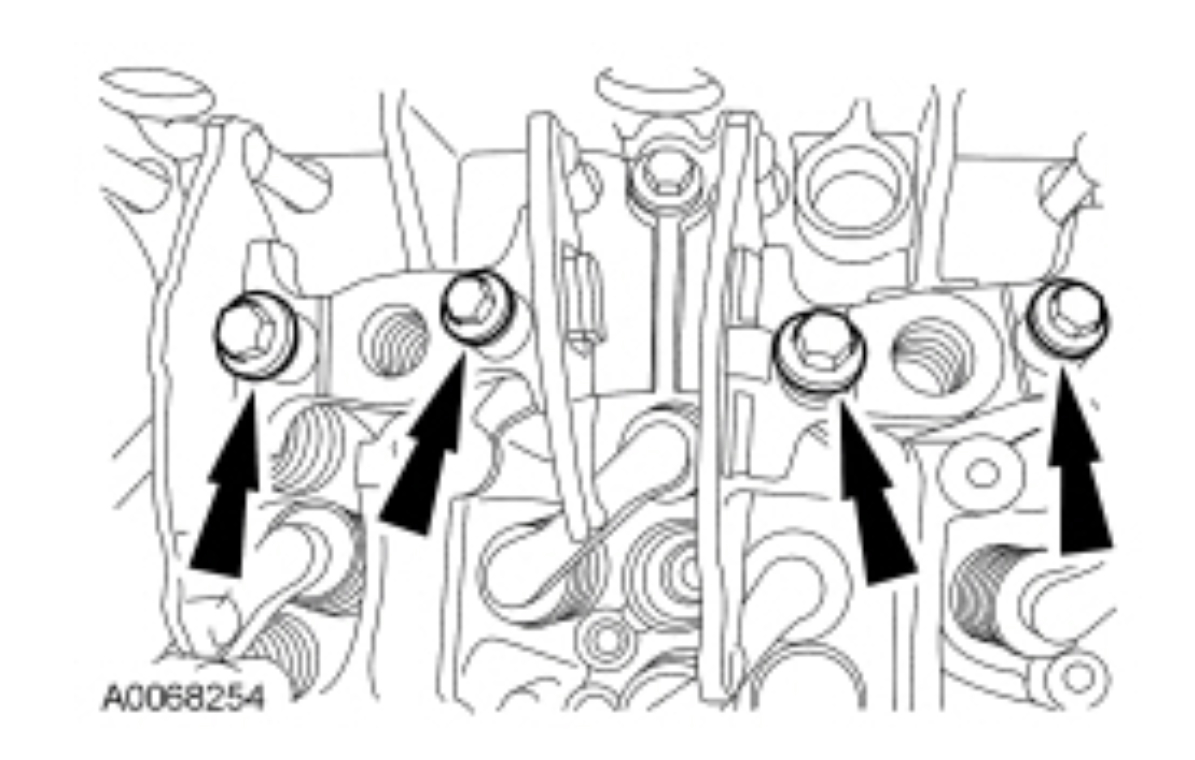
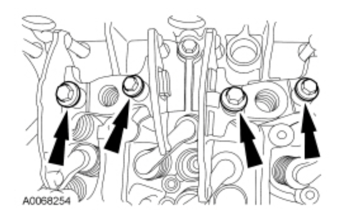
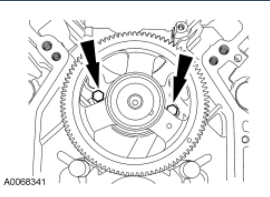
Remove the 10 outer head bolts.
pic 72
Using the Cylinder Head Lifting Bracket, remove the cylinder heads.
pic 73
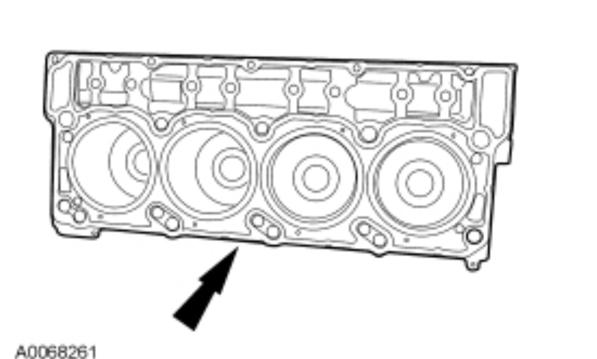
Check for cylinder head distortion. For additional information, refer to Cylinder Head Distortion in this section.
Remove and discard the cylinder head gaskets.
pic 74
Remove and discard the 4 cylinder head dowel sleeves.
pic 75
Check the cylinder block distortion. For additional information, refer to Cylinder Block Distortion in this section.
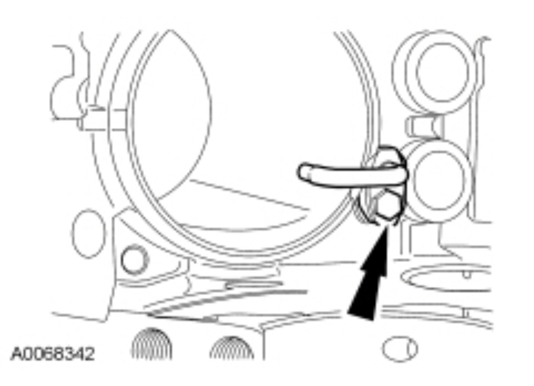
Remove the bolts and the high-pressure oil branch tube.
pic 76
NOTICE: To prevent engine damage, keep the cam followers in the order in which they were removed. Install all cam followers back in their original positions.
Remove the 2 bolts, the roller follower guides and the hydraulic cam followers.
pic 77
Remove the 9 bolts and the upper oil pan.
Remove and discard the press-in-place gasket.
Clean and inspect the sealing surfaces.
pic 78
NOTE: Prior to removing any piston and connecting rod assemblies, it is recommended that piston protrusion be evaluated. This will help identify bent or twisted connecting rods.
Check the piston protrusion above the crankcase as follows:
Position the Dial Indicator Gauge with Holding Fixture.
Zero the Dial Indicator Gauge on the crankcase deck surface.
Position the Dial Indicator Gauge tip on the piston head at the 3 o'clock or 9 o'clock position.
Rotate the crankshaft to measure the maximum piston protrusion and record.
Reposition the Dial Indicator Gauge tip onto the piston head at the opposite position.
Rotate the crankshaft to measure the maximum piston protrusion and record.
Average the 2 readings. If the average reading is lower than the specification, the piston is lower in the bore than it should be. This indicates a bent or twisted connecting rod.
pic 79
Using a Feeler Gauge Set, check for the minimum connecting rod side clearance.
pic 80
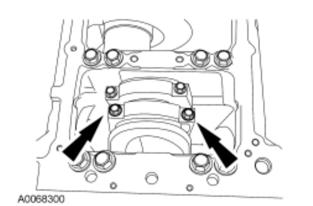
NOTE: Only one connecting rod cap shown.
Remove the 16 bolts and the connecting rod caps.
pic 81
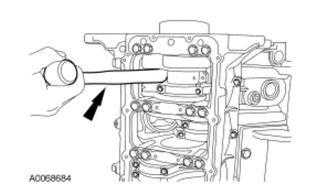
NOTICE: To prevent engine damage, remove the ridge prior to removing the rod and piston assemblies if evident from the top of the cylinder bore. This reduces the chance of piston ring land damage during removal.
Use a razor knife or emery board to scrape the carbon ridge from the top of the cylinder bore.
Using a wood or plastic hammer handle, push the connecting rod and piston assembly out of the cylinder bore.
pic 82
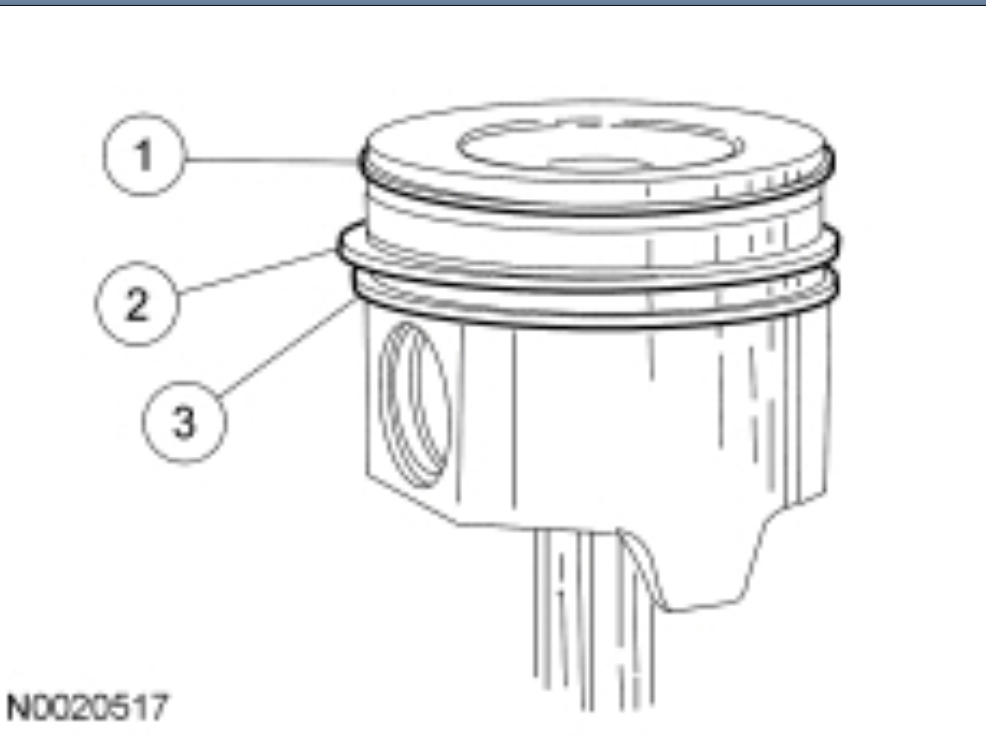
Remove and discard the piston rings.
Remove the keystone ring.
Remove the intermediate compression ring.
Remove the oil control ring.
pic 83
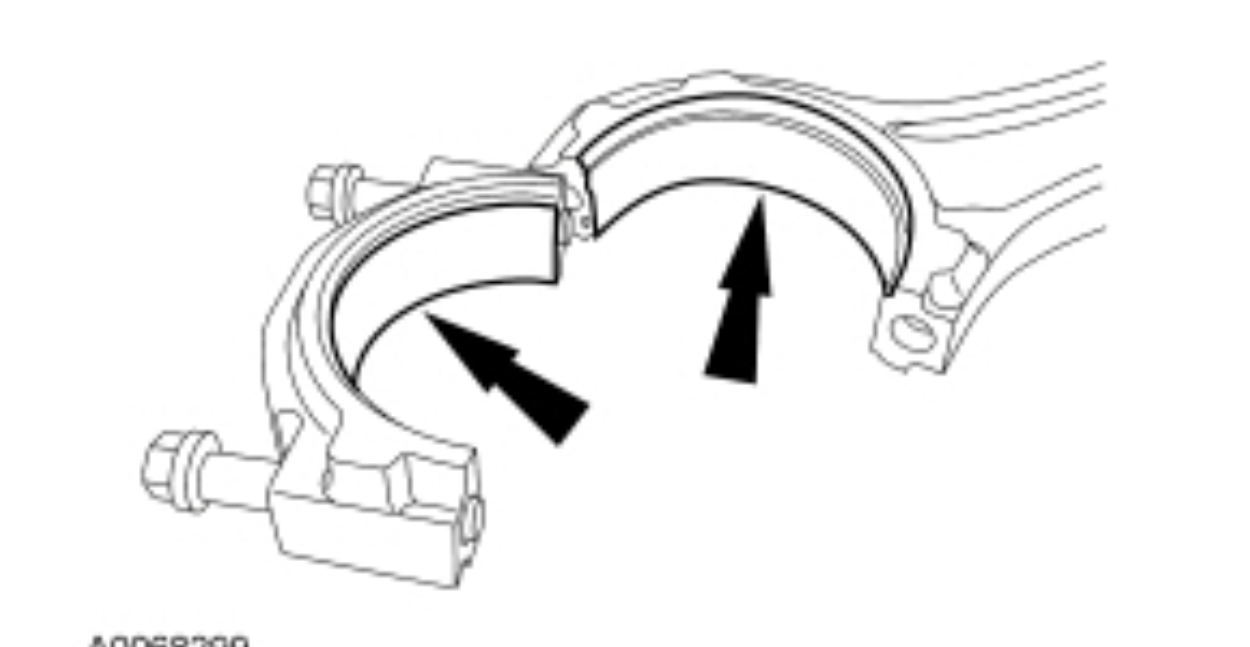
Remove and discard the connecting rod bearings.
pic 84
Install the Dial Indicator Gauge with Holding Fixture and measure the camshaft gear backlash. Install a new gear if backlash is not within specification.
pic 85
Install the Dial Indicator Gauge with Holding Fixture and measure the camshaft end play. Install a new camshaft thrust plate if end play is not within specification.
pic 86
NOTICE: To prevent engine damage, do not remove the rear primary crankshaft flange bolts under any circumstances. If the flange is removed and reinstalled, it will result in engine vibration and premature transmission component wear.
Install the Dial Indicator Gauge with Holding Fixture and measure the crankshaft end play. Record the end play.
pic 87
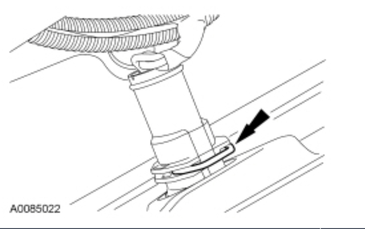
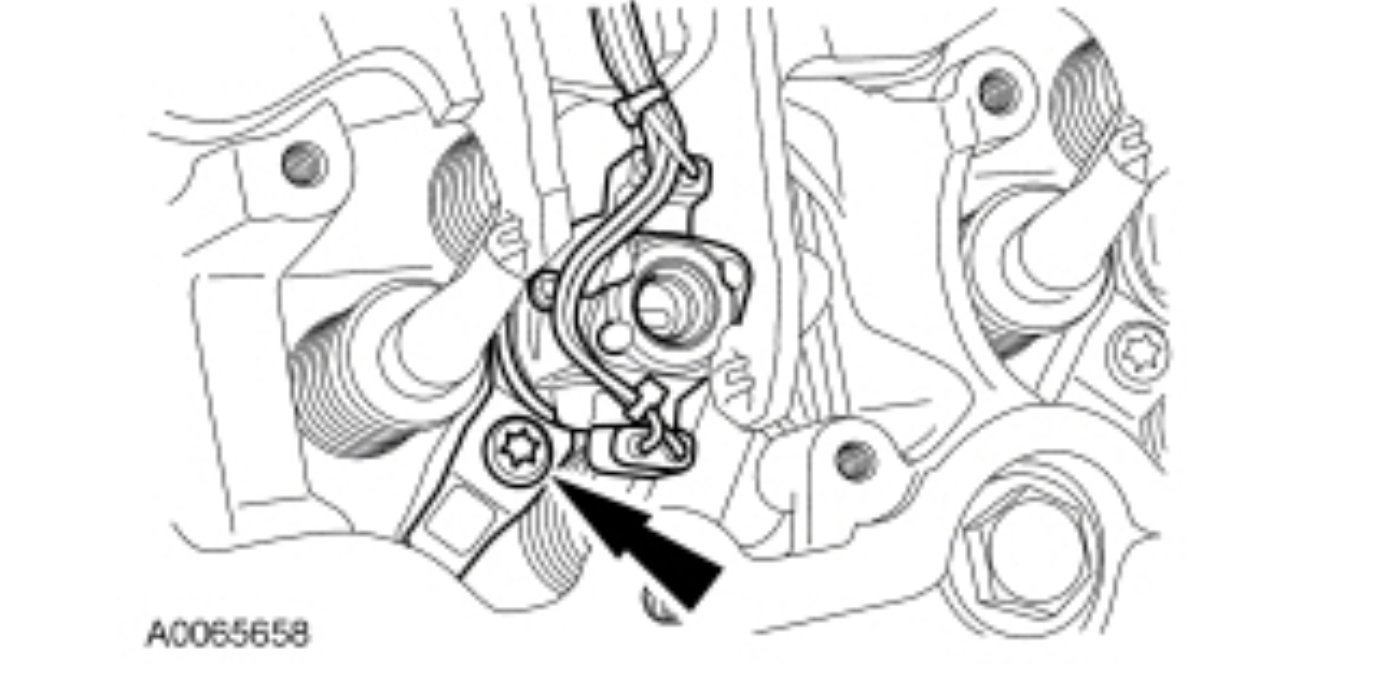
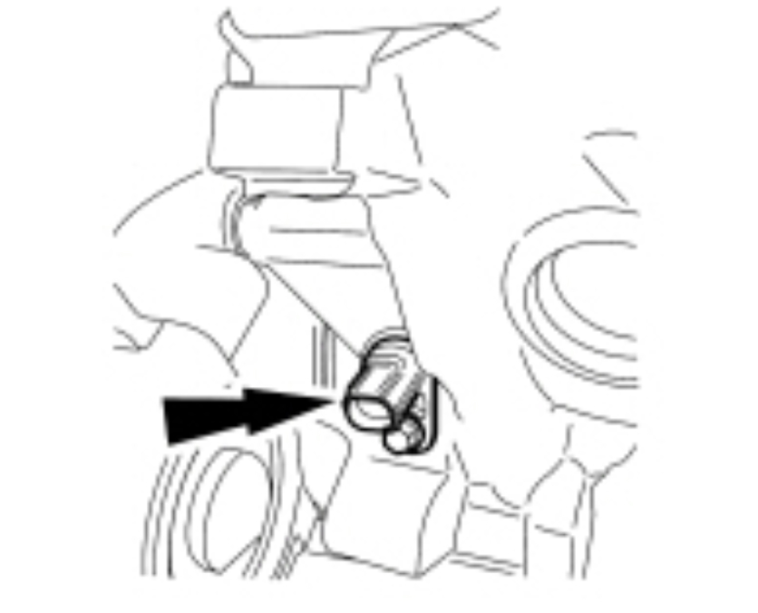
Remove the bolt and the Crankshaft Position (CKP) sensor.
pic 88
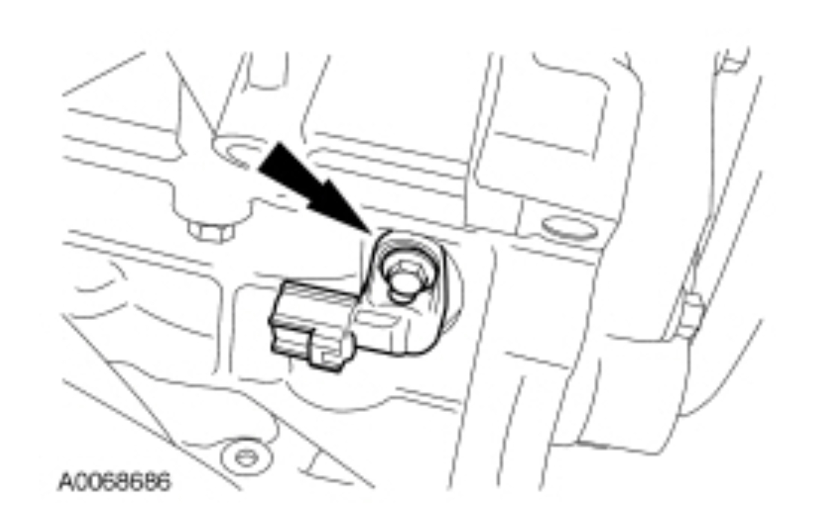
Remove the bolt and the Camshaft Position (CMP) sensor.
pic 89
Remove the block heater.
pic 90
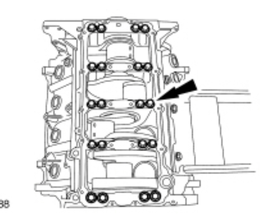
Remove the 20 lower case bolts and the lower crankcase assembly.
pic 91
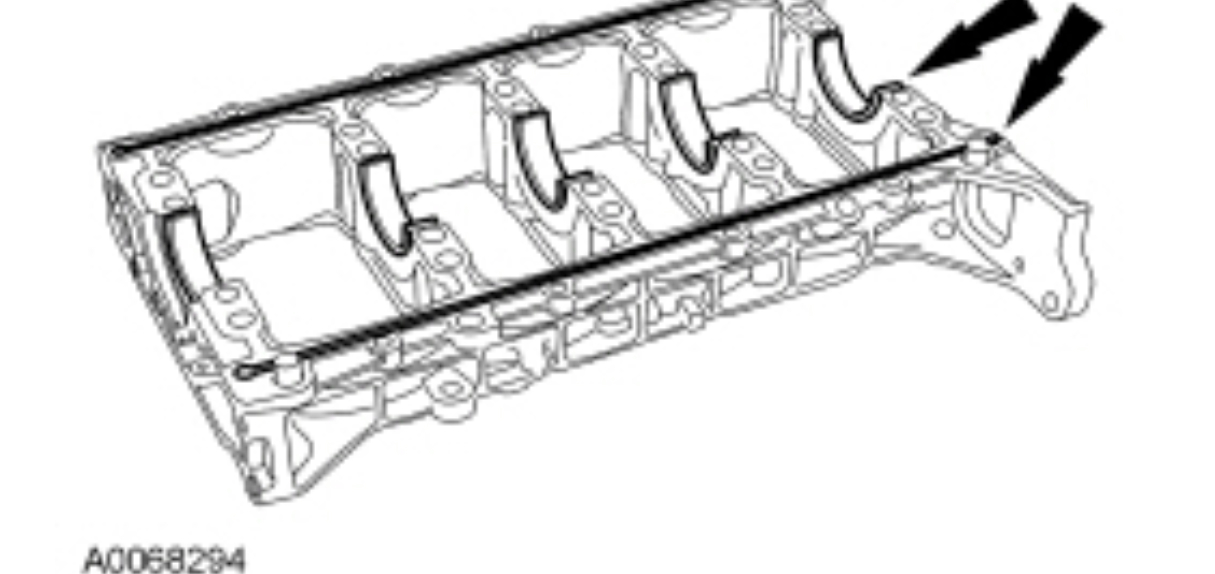
Remove the lower crankcase seals and the lower bearings and discard.
pic 92
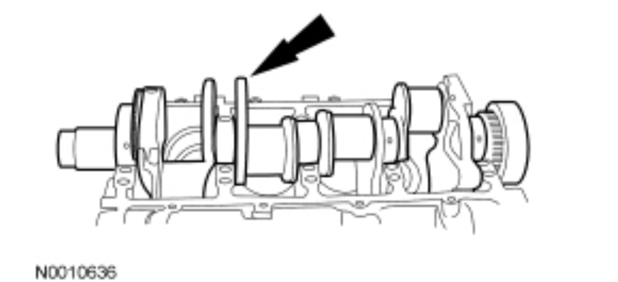
Using the appropriate lifting device, remove the crankshaft assembly.
pic 93
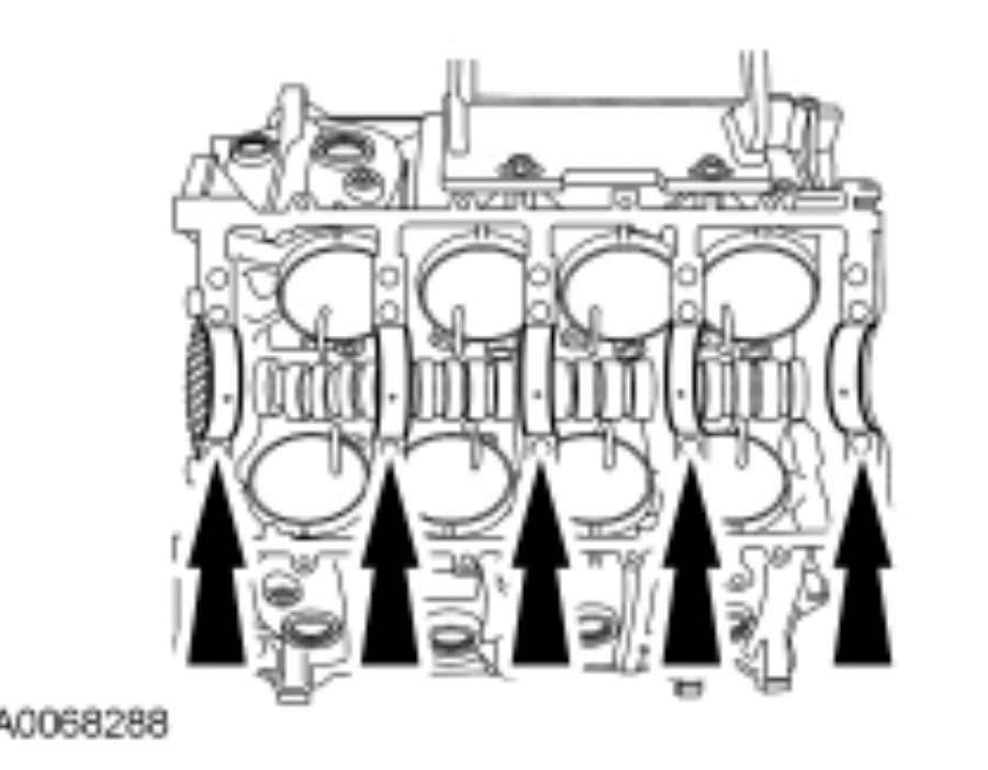
Remove and discard the crankshaft upper bearings and crankshaft upper thrust bearing.
pic 94
NOTICE: Do not nick or scratch the camshaft bearings with the camshaft lobes or engine damage may occur.
Remove the 2 thrust plate mounting bolts and remove the camshaft and gear.
pic 95
NOTICE: This patch bolt is unique. Do not substitute or engine damage can occur.
Remove the 8 bolts and the 8 piston cooling tubes.
pic 96
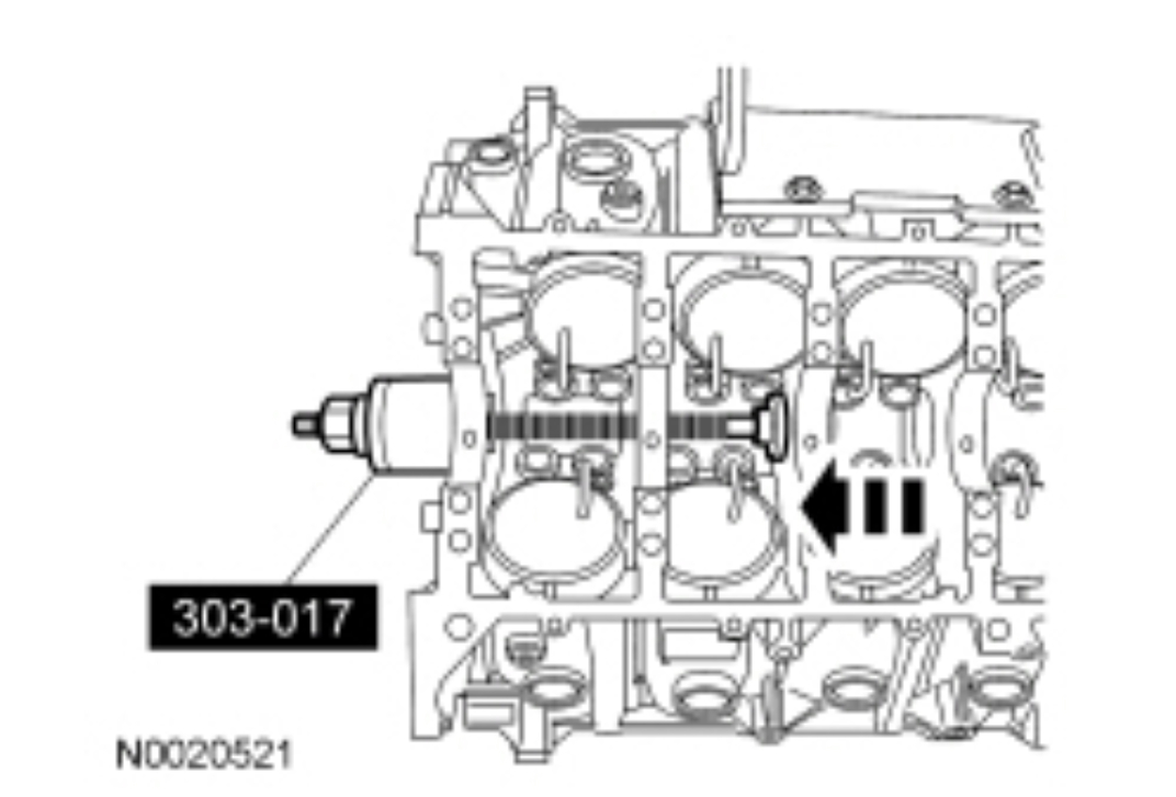
Using the Camshaft Service Set, remove the camshaft bearings and discard.
pic 97
________________
Let me know if this helps.
Joe
Images (Click to enlarge)
Jan 22, 2020 at 8:58 PM