A/C not blowing cold air

2001 CHEVROLET PRIZM
60,000 MILES • 1.8L • 4 CYL • 2WD • AUTOMATIC
Avatar
BOBK123
  • MEMBER
  • 17 POSTS
A/C is out - no cold air (blower is working, I can get heat). The compressor clutch does not look to be spinning. It looks a bit rusted too, although I can turn it by hand. I checked low pressure side and it reads very high, like 94 PSI. The lines look okay and the evaporator looks okay. thank you.
Jun 24, 2021 at 5:57 AM
Advertisement
Avatar
KASEKENNY
  • CERTIFIED EXPERT
  • 18,907 POSTS
Sounds like the compressor is not engaging at all. For the the low side to be 94 PSI that is pretty normal when the system is static.

When the compressor engages it pulls the low side down and builds the pressure on the high side.

I suspect you have one of two issue. Either the compressor is not functioning due to no power or the compressor has failed.

Let's start with checking for power at the compressor and we can go from there.

https://www.2carpros.com/articles/how-to-check-wiring

I attached the wiring diagram below for your review.

Also here is a guide that will help with more info on this:

https://www.2carpros.com/articles/car-air-conditioner-not-working-or-is-weak

Let me know what questions you have.

Thanks
Jun 24, 2021 at 6:38 PM
Avatar
BOBK123
  • MEMBER
  • 17 POSTS
Hi Kenny,

Thanks very much for your reply, and sharing the links and diagrams! I have a multimeter, so I'll check if voltage is getting to the compressor. I'll reply with what I find.
Jun 25, 2021 at 12:05 PM
Advertisement
Avatar
BOBK123
  • MEMBER
  • 17 POSTS
Hi Kenny,

I see two different harnesses going to the compressor. One has 2 wires, which looks like it matches the wiring diagram, the wires are white/black and blue/yellow (I think yellow, hard to see for sure). I pulled the connector and checked voltage (touched multimeter probe to the inside of the connector where the blue/yellow wire goes.) It reads 0.1 volts with the A/C on or off. Blower is on high when testing. So not getting voltage here.

The other connector has 4 wires. Picture attached - this connector is in place, I didn't pull it off. Do you know what this harness is for? Do I need to check voltage here?

thanks

PS: the blue/yellow wire looks like it's making a solid connection at the connector - it's not loose or frayed.
Jun 26, 2021 at 11:20 AM
Avatar
KASEKENNY
  • CERTIFIED EXPERT
  • 18,907 POSTS
The two wires that you removed and tested is for the compressor clutch and should have 12 volts when the A/C is on.

So we need to go to the relay and check for voltage there and test the relay. Here is a guide that will help with this:

https://www.2carpros.com/articles/how-to-check-an-electrical-relay-and-wiring-control-circuit

I would swap the relay or replace it as that is the likely issue. You can also jump the relay (pin 1 to 3) to see if the compressor comes on. If so then the relay is the issue or the PCM is not grounding the relay but let's start with this and go from there. Thanks
Jun 27, 2021 at 8:20 PM
Avatar
BOBK123
  • MEMBER
  • 17 POSTS
thanks very much I will check the relay tomorrow. In the meantime, to help me understand the wiring diagram, I have a couple of questions. There's another component between the relay and the compressor clutch, Fuse and Relay Block 1 (beneath the relay on the diagram). Is this a fuse? I'm confused because the blue/yellow power wire for the clutch looks like it comes from this component Pin 9, but there's a break between Pin 9 and the clutch, and the wire colors change at this break.
Jun 28, 2021 at 1:08 AM
Avatar
BOBK123
  • MEMBER
  • 17 POSTS
Hi Kenny,

I have some interesting findings. The relay is good. I swapped it with the relay next to it, (same model relay), and no change. I can also hear a faint click in both relays when the car ignition starts.

Then I pulled the relay and probed the points. The one point that seems totally off is terminal 85 ground. There's no continuity when I check it with the multimeter's other probe touching battery ground.

As for the other relay points - I think these are correct, assuming the relay switch is not closing:
Terminal 86 reads 14.5v with AC or blower on; no voltage with AC/blower off.
Terminal 87 (output) reads continuity with the compressor chassis, but 0.1v when AC/blower is on or off, so I assume switch is not closing.
Terminal 30 (battery) reads 14.5v with AC on or blower on; no voltage with AC/blower off.

So...is the problem no ground reaching the relay? On the diagram it looks like it comes from the compressor control module? That part of the diagram is cut off. Please advise as to the next step!

thank you
Jun 28, 2021 at 1:07 PM
Avatar
BOBK123
  • MEMBER
  • 17 POSTS
Hi again Kenny,

When I was checking the relay I forgot to jump it, so I did just now - I jumped pin 5 to pin 3 - and the compressor kicked in right away. Clutch is spinning and getting plenty of cold air. :) Low side pressure reads 39 psi. So great to know the compressor and clutch seem to be working.
Jun 28, 2021 at 5:25 PM
Avatar
KASEKENNY
  • CERTIFIED EXPERT
  • 18,907 POSTS
That is great. Yes. If you jump it and get that operation then that is perfect.

As for the testing that you did on the relay, I suspect you are correct that there is no ground but we need to test it a little differently then you did.

This is not going to have a constant path to ground as the compressor control module controls the compressor by opening the circuit on the ground side. So we call this a low side driver.

Take a look at the wiring diagram below. You are only going to have continuity to ground on that terminal when the control module is closed.

The way to test this is to remove the relay, put your black meter lead on this terminal and then the red meter lead on battery positive. Then turn the engine on and the AC on. Does your meter read battery voltage? If it does then the control module is grounding the circuit. If not, then the control module is the issue.

You are correct that you have .1 volts on the compressor circuit because the relay is not closing.

You need the control module to ground the control side of the relay so that it closes the relay to turn on the compressor.
Jun 29, 2021 at 7:34 PM
Avatar
BOBK123
  • MEMBER
  • 17 POSTS
Thanks very much. From what you say, I understand that I won't see constant ground on terminal 85. I'll see ground only with the control module closed.

What is (and where is) the control module? is it part of the HVAC unit in the dash? Does turning on the A/C button on the dash directly close the control module?
Jun 29, 2021 at 8:45 PM
Avatar
KASEKENNY
  • CERTIFIED EXPERT
  • 18,907 POSTS
That is correct. It is a ground control relay. That means it is an open circuit until the control module wants it on. Then it applies the ground and that completes the circuit and current flows through the coil in the relay which closes the contacts in the relay and then this allows power to flow to the compressor.

Let me know if you have questions on this. Thanks
Jul 1, 2021 at 5:57 PM
Avatar
BOBK123
  • MEMBER
  • 17 POSTS
Thanks for the info! I've been out of town so I haven't been able to test the ground as you suggested, but I'll get to it this weekend. In case the control module does need to be replaced, can you confirm if this is the part?

https://www.amazon.com/ACDelco-15-21529-Original-Equipment-Conditioning/dp/B000EQQMUW

I searched the AC Delco site and this unit came up as the compatible part - HVAC Control Module. But it seems very hard to find - it's out of stock.

thanks!
Jul 1, 2021 at 8:34 PM
Avatar
KASEKENNY
  • CERTIFIED EXPERT
  • 18,907 POSTS
Okay. Sounds good. Yes. A/C control module is what you want. The location is number 13 below.

Let us know how you make out but you may need to seek one in a salvage yard.
Jul 2, 2021 at 8:31 PM
Avatar
BOBK123
  • MEMBER
  • 17 POSTS
I tested the relay ground as you asked, by turning on the A/C and probing relay ground (terminal 85) and battery +. I read 13.2v. So assuming I'm checking it correctly - which I would like to confirm! - it means the control module is closing. Thing is, when I turn off the AC I still read the same voltage. So I don't know if that makes sense - shouldn't the control module prevent ground from reaching the relay when the A/C is off?

As for the relay terminals, can you please confirm that I'm probing the correct points? I found this diagram https://benignblog.com/denso-relay-wiring-circuit-diagram which matches the relay pretty closely. My relay is Denso starting with 156700. I want to be sure that this webpage diagram is showing the pins on the the relay, and not the slots on the relay connector. The slots on the relay connector would be the mirror image, correct?
Jul 3, 2021 at 5:25 AM
Avatar
KASEKENNY
  • CERTIFIED EXPERT
  • 18,907 POSTS
That does appear to be correct but when you tested this, was the engine running?

Take a look at this attachment. Let's just confirm this is what you are seeing at the control module.

They are having you test it at the module to determine if the module is functioning so they may be using different logic to control this because I would not expect to see no or little voltage when it is operating. However, that is what they are calling for.

It is the blue and black wire on the module.
Jul 3, 2021 at 8:15 PM
Avatar
BOBK123
  • MEMBER
  • 17 POSTS
Engine was running for my tests. Can you just let me know - with A/C off and engine on, should I be getting ground at the A/C MG relay terminal 85?

And I'm not 100% clear on your last message - do I need to access the control module and probe the blue/black wire (terminal 9) at the point where it connects to the module? Since this is ground I assume I will do the same type of test - black probe to control module and red probe to battery + ?

As for getting to the control module, I can't find anything online about accessing it. I see the location of the control module from your diagrams. Do you know if I can access it by just removing the glove box?

Jul 4, 2021 at 6:53 AM
Avatar
KASEKENNY
  • CERTIFIED EXPERT
  • 18,907 POSTS
Yes. We need to access the control module and test this as we need to do it with the relay installed. I suspect the control module is the issue but there may be a resistor inside the module that is not sensing the resistor installed and so it is not commanding the relay to close. This is not a traditional simple grounding circuit within the module or you would be getting the opposite voltage when the A/C is off.

If you remove the glove box you should be able to access it. Take a look at the attachment below. You test this by red lead in this blue/black wire and the black lead on ground (pin 4) so you can monitor the voltage.

We might as well check each of them. Here are what the expected values for each wire. Let us know what each value is with the system in the condition noted in the last column.
Jul 4, 2021 at 10:03 AM
Avatar
BOBK123
  • MEMBER
  • 17 POSTS
I located the module and checked voltage on all the terminals - see attached for results!
I did what you suggested, black probe touching wire 4 ground, and red probe to each of the other wires one at a time, following the conditions stated.

Terminal 9 Relay Control is definitely off from the normal voltage in both conditions. Of the others, some are reading correct and others are off.
Jul 5, 2021 at 11:23 AM
Avatar
KASEKENNY
  • CERTIFIED EXPERT
  • 18,907 POSTS
Wait a minute. You have 0 volts on the pressure switch circuit (pin 1). That explains why we are seeing the odd voltage that did not make sense and I assumed there was logic in the module that was using these voltages differently. This should be 12 volts any time the key is on and you have 0 which means the pressure switch is either faulty or the pressures are not accurate.

This also explains why when you put power to the compressor it comes on because you are basically bypassing this sensor.

I would replace the pressure sensor and then check the operation of the compressor again because it appears you already checked the pressures and they are fine. That should set the voltages back to what they should be.
Jul 6, 2021 at 5:48 PM
Avatar
BOBK123
  • MEMBER
  • 17 POSTS
Okay, sounds good! Can you confirm if this is the correct part? https://www.gmpartsbin.com/p/Chevrolet_2001_Prizm-LSi-Sedan-18L-AT/HVAC-Pressure-Switch/48817117/52484739.html
Jul 7, 2021 at 8:13 AM
Avatar
KASEKENNY
  • CERTIFIED EXPERT
  • 18,907 POSTS
Sorry for the delay. That looks like it.

I attached the OEM part number below from the manual just for reference but it is the same number so you are good to go.
Jul 8, 2021 at 8:37 AM
Avatar
BOBK123
  • MEMBER
  • 17 POSTS
I don't think I can discharge and recover the refrigerant in the system without special equipment. So I asked a local mechanic about doing the service. I can get the part and bring it in. But he said I can try jumping the pressure switch to see if the switch is bad. Does this make sense?
Jul 9, 2021 at 5:44 PM
Avatar
KASEKENNY
  • CERTIFIED EXPERT
  • 18,907 POSTS
I thought about that earlier but this is a dual pressure switch which means it shuts down when pressure is high or low. They are normally 3 wire sensors which means it sends a signal to the control module. However, looking at this again that is not the case on this vehicle.

Your pressure switch is an on off switch so you can jump it. Basically it looks for 12 volts or 0 volts. So just disconnect it and put a wire between the two terminals and then turn the ignition and A/C on. It should come on. This confirms the sensor is the issue.

Great idea and glad you mentioned it to make me look again. That's what I get for assuming.
Jul 10, 2021 at 4:47 PM
Avatar
BOBK123
  • MEMBER
  • 17 POSTS
Hi Kenny,

I removed the pressure sensor connector and jumped it, but the compressor clutch did not start spinning, so no luck. But I see there are 4 terminals on this connector, in a diamond type pattern. Blue/red and yellow/black are opposite from each other, these are the terminals I jumped. The other two look like blue/black and green.

Just to confirm I did the right thing, I jumped the points on the connector, not on the switch itself.

Then I checked for voltage on the connector. Blue/red has 14v (I probed blue/red and battery -). Yellow/black I assume is ground. But when I probe yellow/black and battery + I get no voltage reading.
Jul 11, 2021 at 8:54 AM
Avatar
KASEKENNY
  • CERTIFIED EXPERT
  • 18,907 POSTS
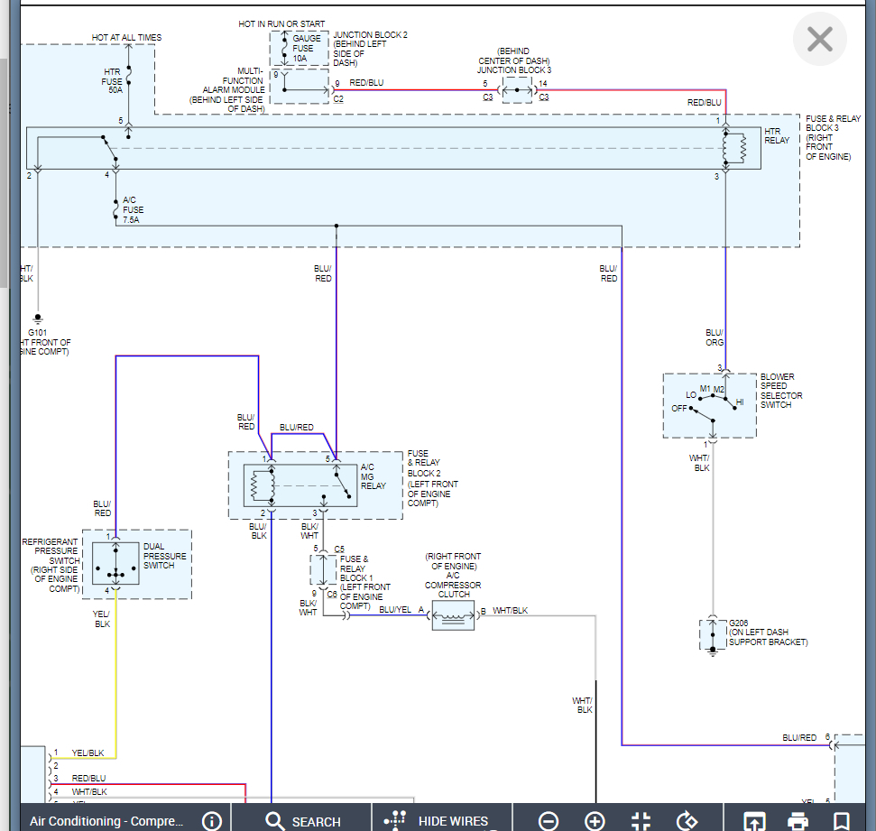
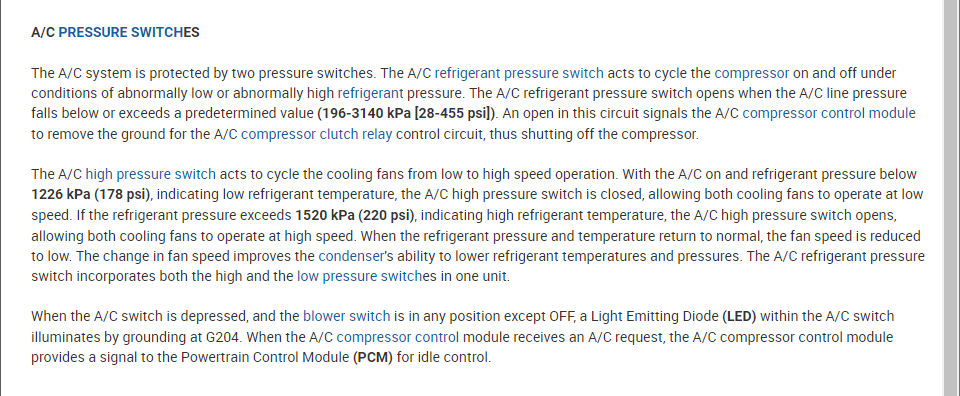
That is correct. Basically they are using this switch to control the fan speed as well to keep the engine cool and air flow over the condenser.

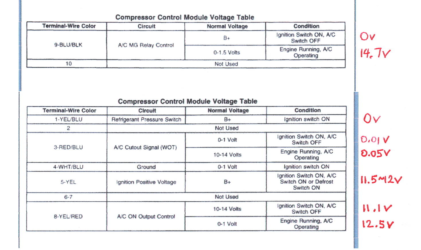
This is progress. This is showing that the module is not grounding this circuit.

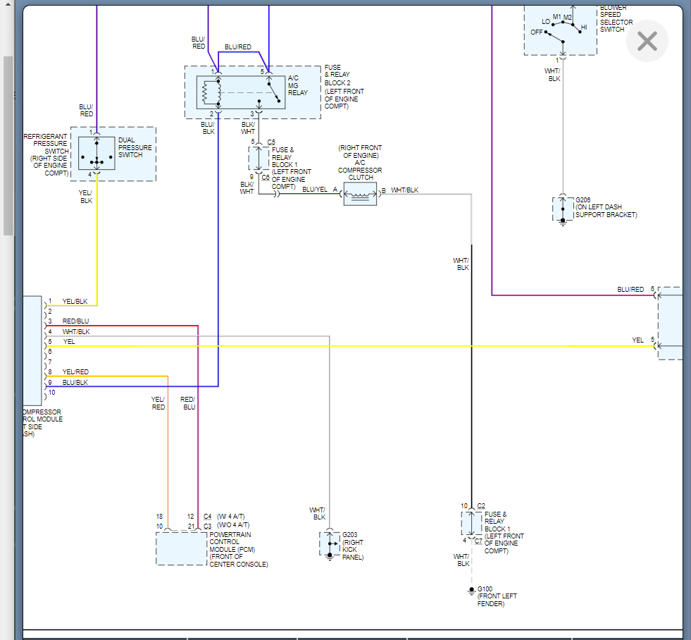
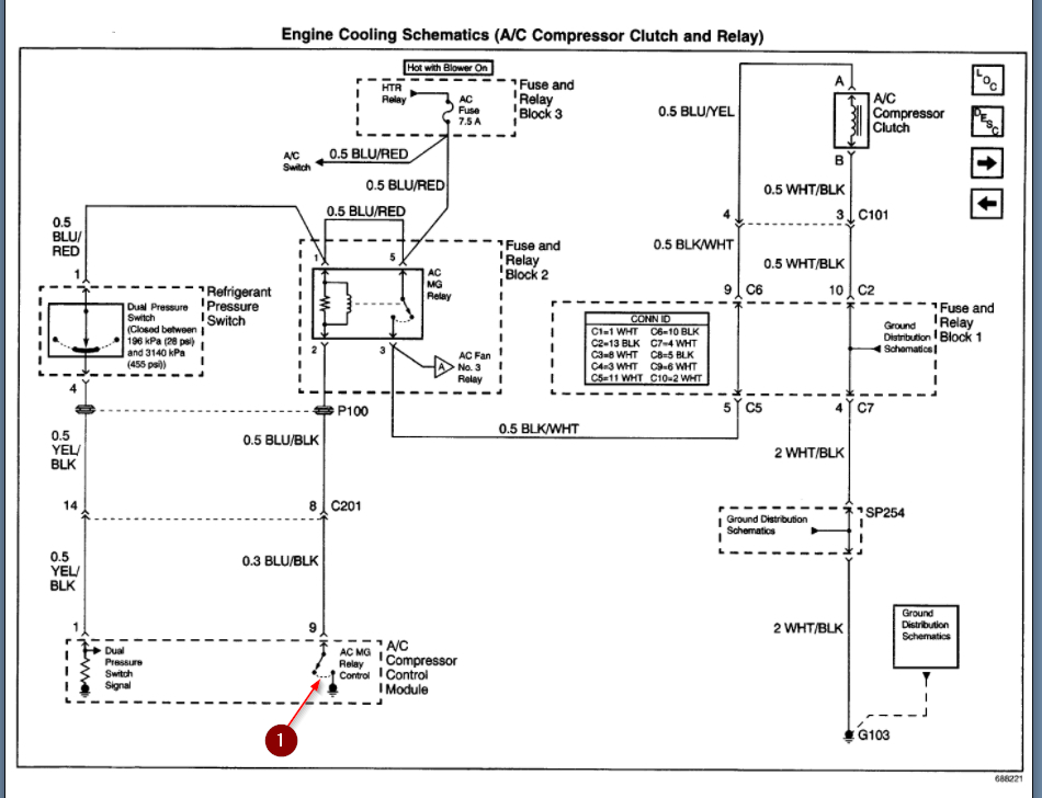
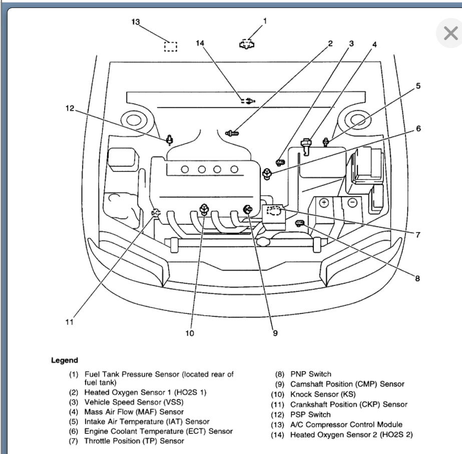
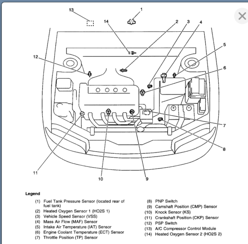
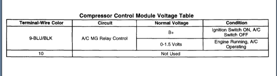
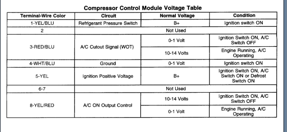
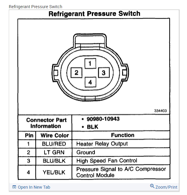
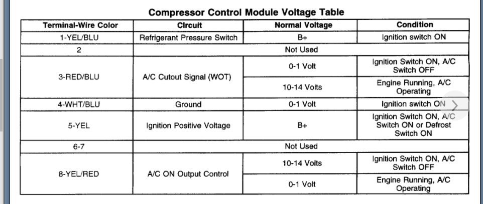
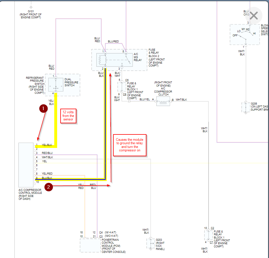
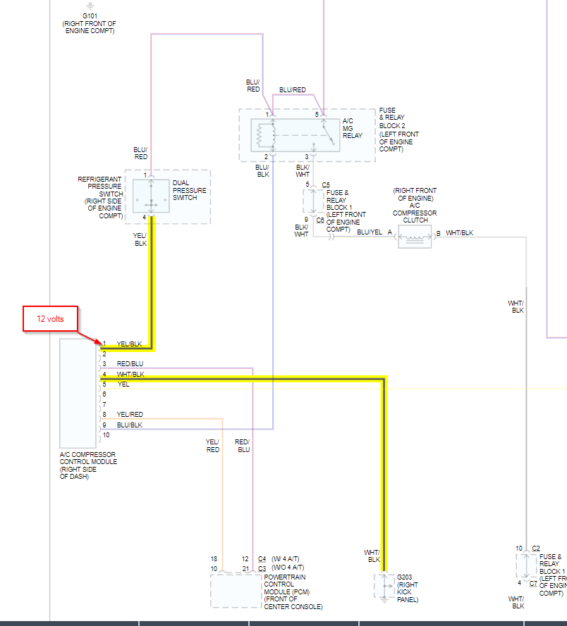
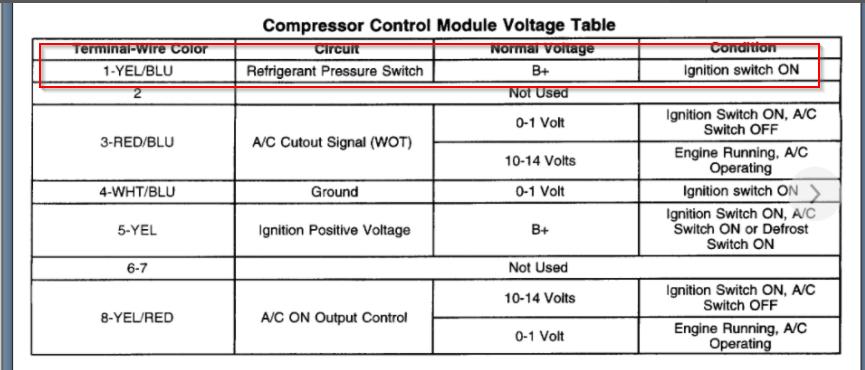
Here is what you should have: At the control module, it needs to see 12 volts on pin 1. This shows that the pressure is correct and it is ok to turn the compressor on.

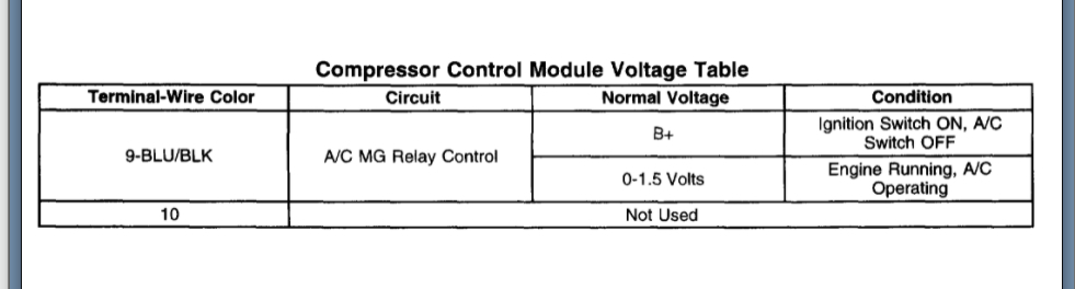
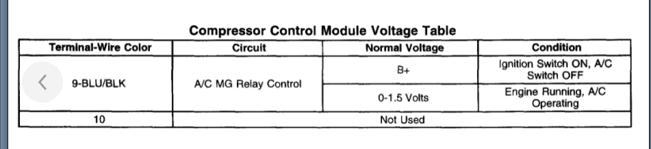
Then the control module will ground the relay on pin 9 and you will see 0-1.5 volts at the control module on this wire. You have battery voltage which shows it is not grounding the circuit.

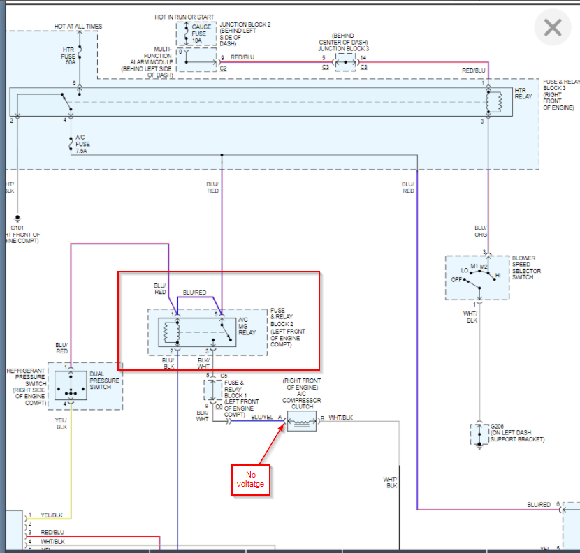
You have 0 volts on pin 1 so it is cutting the compressor off which is why the two wires going to the PCM are not reading the correct voltage either because this is the AC module telling the PCM that the compressor is off.

If jumping that switch does not cause the compressor to come on then we are back to the control module.

What I would do from here is just make sure you don't have a wiring issue from the switch to the module by jumping the switch again and then check voltage at the module on this wire, Pin 1. You should have the same voltage that you do at the switch. If you do then the module is the issue.

Another way to confirm this is to just leave everything connected and jump 12 volts from the battery directly to Pin 1 of the module. If the compressor comes on then it is not getting 12 volts and you have a wiring issue.

Take a look at this below. Please let me know if you have other questions and what you find. Thanks
Jul 11, 2021 at 9:27 AM
Avatar
BOBK123
  • MEMBER
  • 17 POSTS
Thanks for all the help Kenny! I had to think this through after reading it a few times. But now I do understand what you're saying.We're trying to find out if there's a wiring issue between the pressure switch pin 4 (yellow/black) and the control module pin 1 (not sure why it says yellow/blue in the voltage table diagram? but I assume this is the same wire). I may not get to testing this till the weekend. But I will let you know as soon as I find out.
Jul 12, 2021 at 5:44 AM
Avatar
KASEKENNY
  • CERTIFIED EXPERT
  • 18,907 POSTS
Don't worry about the wire color. That could be an issue with the wiring diagram. They often changed the color wire when the run out of one, they switch to another.

Let us know what you find when you get to it. Thanks
Jul 12, 2021 at 5:59 PM
Avatar
BOBK123
  • MEMBER
  • 17 POSTS
Hi Kenny,

I completed both the tests you suggested, and i think it's looking like it's a bad control module. Please confirm. This is what I just did:

I jumped the pressure switch, then with the engine running and the AC/blower on, I checked voltage at pin 1 of the control module. I read 14v, same voltage present at pin 1 of the switch (I did this by probing with my meter on the control module, red to pin 1 and black to pin 4 ground). So I assume this confirms the wiring between the pressure switch to pin 1 of the control module is good.

Then I reconnected the pressure switch connector, and jumped 12v directly from battery + to control module pin 1. With the engine running and AC/blower on, the compressor clutch did not come on - still no A/C.

One Question - do we know for sure that the pressure switch is good? (If the pressure switch was the problem, would the A/C have turned on when I jumped it?)

Thank you!
Jul 18, 2021 at 12:33 PM
Avatar
KASEKENNY
  • CERTIFIED EXPERT
  • 18,907 POSTS
That is excellent. You are exactly correct. If you look at the chart and wiring diagram below.

You need 12 volts at pin one in order for the module to know that the pressure is ok. If you jumped the switch and then checked voltage at the module using the modules ground and you have 12 volts on your meter then you verified the entire circuit.

If the module has 12 volts on pin 1 and it still does not come on then the module would be the issue.

However, you appear to have an issue with the switch as well.

The jumping of the switch is a clear and simple test. If you have to jump the switch in order to get 12 volts to the module then the switch has failed.

If it were me, I would replace the module and then jump the switch again which should cause the compressor to come on. If it does, replace the switch. However, if you want to put the switch on it now, I would understand because this is a simple on off switch based on pressure. So either it is closed or open based on the pressure and if the pressure is correct and it still is open then it is faulty.
Jul 19, 2021 at 9:00 AM
Avatar
BOBK123
  • MEMBER
  • 17 POSTS
Thank you! Since the pressure switch needs to be replaced I will first have that done by my mechanic. I went ahead and ordered the part. I'll let you know when that's done.

Is there a chance that the pressure switch is the only problem? I know we jumped the switch to determine it is bad. If the bad pressure switch is staying open will this prevent the compressor from turning on, even when it is jumped?
Jul 19, 2021 at 12:39 PM
Avatar
KASEKENNY
  • CERTIFIED EXPERT
  • 18,907 POSTS
Normally yes. However, when you jump it the compressor should come on if it were the only issue. All the switch does is provide 12 volts to the module which tells it the pressure is not to low or high. So if you not only jumped it but then applied 12 volts to it and it still did not come on then we have another issue.

Let us know how you make out with this. Thanks
Jul 19, 2021 at 7:10 PM