1986 Nissan Truck Sensor Light

1986 NISSAN TRUCK
90,896 MILES • 4 CYL • 2WD • AUTOMATIC
Avatar
TRAINFAN51
  • MEMBER
  • 7 POSTS
The Sensor Light is on but I don't know how to find the code. My manual says there is an ECU under the drivers seat. And there is, However: the manual says that there should be a SWITCH and a green and red led., or there should be an adjustment screw to turn. The problem is there is only one led and it is green and it does not flash. There is no adjustment screw to turn. And there is no switch. When I turn the key on the sensor light is constant. There is a chime that sounds 9 times but that doesn't match any of the codes.

What next?
Nov 18, 2008 at 4:07 PM
Advertisement
Avatar
JAMES W.
  • CERTIFIED EXPERT
  • 2,394 POSTS
Have you had the truck since it was new? I have gone through all the diagrams from '83 to '86 and your computer "is" supposed to have a red and green led. The single green led is apparently from an older model. If I remember correctly from years back, there is supposed to be a screw you have to run in or out to access the codes and the single green led blinks like the check engine light on a GM. Take another look and let me know.
Nov 18, 2008 at 9:43 PM
Avatar
TRAINFAN51
  • MEMBER
  • 7 POSTS
[quote:4c9da6dd8b="James R. Weizel"]Have you had the truck since it was new? I have gone through all the diagrams from '83 to '86 and your computer "is" supposed to have a red and green led. The single green led is apparently from an older model. If I remember correctly from years back, there is supposed to be a screw you have to run in or out to access the codes and the single green led blinks like the check engine light on a GM. Take another look and let me know.[/quote:4c9da6dd8b]

[Reply="David Laube"]
James: Thank you for your response. We bought the truck used. I pulled out the seat and took the cover off of the computer. There is only one led Green. There is no adjustment screw. Having worked on copier circuit boards this was pretty simple.

The cover for the computer has a large 7 on the label. The part #is A17-001 032-3 With the numbers 5717 in a box.

The number on the circuit board is A16-618 049
Nov 19, 2008 at 12:24 PM
Advertisement
Avatar
JAMES W.
  • CERTIFIED EXPERT
  • 2,394 POSTS
Let me dig a little deeper and I'll try to get back to you yet today, Jim.
Nov 19, 2008 at 3:30 PM
Avatar
TRAINFAN51
  • MEMBER
  • 7 POSTS
[quote:3d1f7b89f8="James R. Weizel"]Let me dig a little deeper and I'll try to get back to you yet today, Jim.[/quote:3d1f7b89f8]


Just wondering if you have come up with something yet? I still have the problem.
Nov 25, 2008 at 10:19 PM
Avatar
JAMES W.
  • CERTIFIED EXPERT
  • 2,394 POSTS
I haven't forgotten you. I need to access a part of my system for the older models and it is down right now. I'll keep trying.
Nov 28, 2008 at 12:23 PM
Avatar
TRAINFAN51
  • MEMBER
  • 7 POSTS
[quote:72384f32f6="James R. Weizel"]I haven't forgotten you. I need to access a part of my system for the older models and it is down right now. I'll keep trying.[/quote:72384f32f6]


Ok. Thanks I really appreciate your help I just can't believe this hasn't come up enough time to where it isn't in the manual. But I'm sure this doesn't suprise you.
Nov 28, 2008 at 11:51 PM
Avatar
STRAILER
  • CERTIFIED EXPERT
  • 53,854 POSTS
Hi, I had one of those trucks so I cant help you, to run the codes you need to turn the key to the on position, then on the side of the comp there is a small switch or screw, this switch controls the "mode" the computer is in, after the switch is thrown one or both lights will flash, one, two, three, four blinks, when it gets to four throw the switch back, then it will flash you the codes, tens then ones, example, first light will flash "one" the second light flashes 4 times, code number 14. turn the key of to return to normal mode. If your comp has a screw turn it for "on" then trun it back for off, please let me know how it goes. To clear code disconnect the battery for 5 mins.


:-)
Nov 29, 2008 at 1:18 AM
Avatar
TRAINFAN51
  • MEMBER
  • 7 POSTS
[quote:5eb416dd5f="2CarPro Ken"]Hi, I had one of those trucks so I cant help you, to run the codes you need to turn the key to the on position, then on the side of the comp there is a small switch or screw, this switch controls the "mode" the computer is in, after the switch is thrown one or both lights will flash, one, two, three, four blinks, when it gets to four throw the switch back, then it will flash you the codes, tens then ones, example, first light will flash "one" the second light flashes 4 times, code number 14. turn the key of to return to normal mode. If your comp has a screw turn it for "on" then trun it back for off, please let me know how it goes. To clear code disconnect the battery for 5 mins.

2CarPro Ken Thanks for your input, please see my response to James R. Weizel. I took the computer out and looked at the circuit board. There is neither a srew to turn or a switch. As I explained to James I've worked on circuit boards in copier machines so I knew what I was looking for. The comp only has a green light.


:-)[/quote:5eb416dd5f]
Nov 29, 2008 at 9:36 PM
Avatar
JAMES W.
  • CERTIFIED EXPERT
  • 2,394 POSTS
I have checked every computer system for a nissan p/u from '80 to '87 and can find nothing on the type of computer you have. I've even checked some of the cars. I used to have a repair manual for just Nissan and Toyota car and truck computers up to '88, but I can't find it. Probably lent it out. I'll keep looking, the answer is here somewhere.
Dec 1, 2008 at 10:53 PM
Avatar
STRAILER
  • CERTIFIED EXPERT
  • 53,854 POSTS
Thanks Jim, Does the ECU have a screw with an arrow?
Dec 2, 2008 at 1:19 AM
Avatar
JAMES W.
  • CERTIFIED EXPERT
  • 2,394 POSTS
Yes it does, Jim
Dec 2, 2008 at 11:58 AM
Avatar
STRAILER
  • CERTIFIED EXPERT
  • 53,854 POSTS
that is the "switch" turn the screw one way turns the switch on, then back the other turns the switch off.
Dec 2, 2008 at 12:06 PM
Avatar
TRAINFAN51
  • MEMBER
  • 7 POSTS
[quote:10f5852265="James R. Weizel"]I have checked every computer system for a nissan p/u from '80 to '87 and can find nothing on the type of computer you have. I've even checked some of the cars. I used to have a repair manual for just Nissan and Toyota car and truck computers up to '88, but I can't find it. Probably lent it out. I'll keep looking, the answer is here somewhere.[/quote:10f5852265]

This is weird. I hope you find your manual. Did the part numbers reference anything ?
Dec 4, 2008 at 10:02 AM
Avatar
JNOVACK
  • CERTIFIED EXPERT
  • 723 POSTS
I hope this help this shows how the ecm should look like and is a removel and instal of ecm with all locations
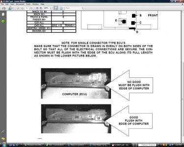

https://www.2carpros.com/forum/automotive_pictures/52960_Untitled_3.jpg


https://www.2carpros.com/forum/automotive_pictures/52960_Untitled11_1.jpg

GOOD FLUSH WITH 
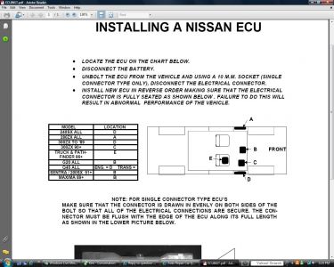
EDGE OF COMPUTERMODEL LOCATION 240SX ALL D 280ZX ALL A 300ZX TO '89 D 300ZX 90+ C TRUCK & PATHFINDER 86+ E G20 ALL B Q45 ALL ENG. = D TRANS = SENTRA / 200SX 91+ B MAXIMA 89+ B NO GOOD MUST BE FLUSH WITH EDGE OF COMPUTER COMPUTER (ECU) · LOCATE THE ECU ON THE CHART BELOW. · DISCONNECT THE BATTERY. · UNBOLT THE ECU FROM THE VEHICLE AND USING A 10 M.M. SOCKET (SINGLE CONNECTOR TYPE ONLY), DISCONNECT THE ELECTRICAL CONNECTOR. · INSTALL NEW ECU IN REVERSE ORDER MAKING SURE THAT THE ELECTRICAL CONNECTOR IS FULLY SEATED AS SHOWN BELOW . FAILURE TO DO THIS WILL RESULT IN ABNORMAL PERFORMANCE OF THE VEHICLE. INSTALLING A NISSAN ECU NOTE: FOR SINGLE CONNECTOR TYPE ECU'S The self-diagnostic system is useful to diagnose malfunctions in major sensors and actuators of the ECCS system. The ECU constantly monitors the function of these sensor and actuator circuits, regardless of ignition key position. If a malfunction occurs, information is stored in the ECU and can be retrieved from the memory by turning on the diagnostic mode selector, located on the side of the ECU. When activated the malfunction is indicated by flashing a red and green LED light emitting diode, also located on the ECU. Since all the self-diagnostic results are stored in the ECU memory, even intermittent malfunctions can be diagnosed. A malfunctioning parts group is indicated by the number of both the red and green LEDs flashing. First, the red flashes, then the green flashes follow. The red LED refers to the number of the tens digit while the green one refers to the number of the units digit. For example, when the red LED flashes three times and then the green on flashes twice, this means the number 32. In this way, all problems are classified by the code numbers. Perform self-diagnosis with engine sufficiently warmed up. After a malfunctioning component has been corrected, be sure to erase memory. To erase code memory: Turn ignition switch ON. Turn diagnosis mode selector ON. Wait for 2 seconds. Turn diagnosis mode selector OFF. Wait 2 seconds. Memory erasure has been completed. The stored memory would be lost if battery terminal is disconnected See Figures 1, 2, 3, 4, 5, 6, 7, 8, 9, 10 and 11


https://www.2carpros.com/forum/automotive_pictures/52960_0900823d8017ae32_1.jpg

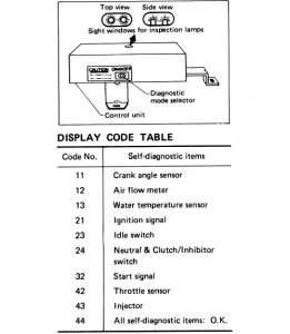
Fig. 1: ECU code table-Z24i engine through 1986


https://www.2carpros.com/forum/automotive_pictures/52960_0900823d8017ae33_1.jpg

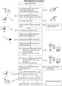
Fig. 2: Diagnostic procedures-Z24i engine through 1986


https://www.2carpros.com/forum/automotive_pictures/52960_0900823d8017ae34_1.jpg

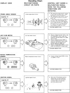
Fig. 3: Diagnostic procedures-Z24i engine through 1986


https://www.2carpros.com/forum/automotive_pictures/52960_0900823d8017ae35_1.jpg

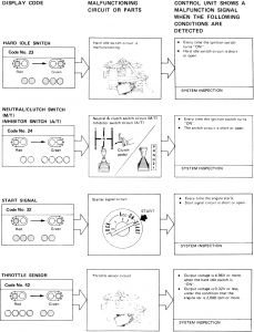
Fig. 4: Diagnostic procedures-Z24i engine through 1986


https://www.2carpros.com/forum/automotive_pictures/52960_0900823d8017ae36_1.jpg

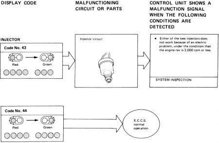
Fig. 5: Diagnostic procedures-Z24i engine through 1986


https://www.2carpros.com/forum/automotive_pictures/52960_0900823d8017ae37_1.jpg

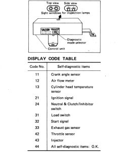
Fig. 6: ECU code table-VG30i engine through 1986


https://www.2carpros.com/forum/automotive_pictures/52960_0900823d8017ae38_1.jpg

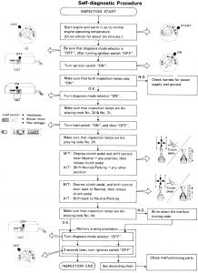
Fig. 7: Diagnostic procedures-VG30i engine through 1986


https://www.2carpros.com/forum/automotive_pictures/52960_0900823d8017ae39_1.jpg

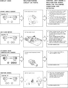
Fig. 8: Diagnostic procedures-VG30i engine through 1986


https://www.2carpros.com/forum/automotive_pictures/52960_0900823d8017ae3a_1.jpg

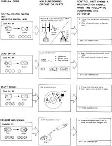
Fig. 9: Diagnostic procedures-VG30i engine through 1986


https://www.2carpros.com/forum/automotive_pictures/52960_0900823d8017ae3b_1.jpg

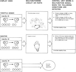
Fig. 10: Diagnostic procedures-VG30i engine through 1986


https://www.2carpros.com/forum/automotive_pictures/52960_0900823d8017ae3c_1.jpg

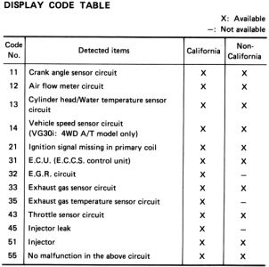
Fig. 11: ECU code table-1987-88 Z24i and VG30i engines
Dec 7, 2008 at 3:28 PM