Okay, now let me explain generators. Everyone will know what you mean when you call them "alternators", but they were developed by Chrysler, and they copyrighted that term. Regardless of what you call them, all generators and alternators work the same way. You need three things, a magnet, a piece of wire, and most importantly, movement between the two of them. In cars we use an electromagnet because we can vary the current flow through it and thus vary the strength of the magnetic field. We will "induce" a voltage into the wire when it moves past the magnet, but by turning the wire into loops, we induce a voltage into each loop, and those voltages add up to give us more than 12 volts coming out to run the electrical system. The movement comes when we spin the electromagnet with the belt and pulley.
There are a number of ways to vary the output. First of all, by its physical nature, the AC generator, (that's an alternator, as opposed to the earlier inefficient DC generators from the 1950s), is incapable of developing more current than it was designed for. Also, it will only develop exactly the amount of current that's needed to run the electrical system and recharge the battery. We don't have to worry about current limiting.
We do have to worry about controlling voltage. Without going into all the detail, (and please do not do this), if you disconnect the battery while the engine is running, it is possible for the output voltage to exceed 30 volts. That will destroy all the computers on the vehicle and burn out any bulbs that are turned on. The voltage regulator is responsible for holding output voltage to a safe level, but it needs the battery to help it do that.
The output voltage is determined by the number of loops of wire in the "stator" winding. That's the wire that we turned into many loops. It is not practical to run alongside the car and pull loops of wire out when the battery is fully-charged, or add loops when we want to roll the power window down. During the manufacturing process, the current output rating can be increased by adding just a few more inches of copper wire in the form of another loop or two, but remember, that only increases the capability of the generator. If the electrical system is calling for 35 amps, it doesn't matter if you have a 90 amp generator or a 120 amp unit. Either one will just develop 35 amps.
We can vary the output voltage by changing the number of windings on the spinning electromagnet, but again, you'd look funny trying to do that with the hood up and zipping down the highway. Since this one creates the magnetic field, we call it the "field" winding. There's no advantage to adding more wire to this one.
The spacing between the stationary "stator" winding and the spinning "field" winding can be changed to vary output voltage. This is how a lot of welders work when they have dials to adjust the current instead of switches. This too is not practical to adjust. GM has had some trouble with their redesigned generators on '87 and newer vehicles. They decreased the spacing so much to get the interaction stronger, but with just a little play in the bearings, the spinning field winding can catch on the stator and lock it up. I've seen some where people had to cut the belt so they could restart the stalled engine.
Another way to vary output voltage is by varying the speed at which we pass the magnetic field through the wire. Because the main ingredient to make this work is the movement, generators of every design are relatively inefficient at low engine speeds. That's why sometimes you'll see head lights dim slightly when the engine is idling. One way to increase the efficiency is to build the metal frame of the field winding with multiple fingers extending around from the north and south poles. That means there will be many north - south transitions per revolution instead of just two. Each transition makes the needed movement. By having more of those transitions, it acts like it's spinning faster.
Getting back to speed, we actually DO vary output voltage when we change engine speed, but just as with everything else up to this point, it is not practical to increase engine speed because you want to turn on the heater fan, and it's not practical to slow down to stop the battery from over-charging.
The only practical way to control output voltage is by varying the strength of the magnetic field. On the older DC generators, we passed up to about five amps through stationary field coils bolted to the housing. The output voltage and current were developed in the spinning armature, then we had to get it out through carbon brushes. If we were lucky, for that five amps in we might get 30 amps out. That was hard on the brushes too to pass that much current through them. Efficiency of these were very low, and if the engine had to idle a lot, you might have to charge the battery once every week or two.
With the AC generator, the high output current is taken off the stationary stator winding and no brushes are involved. The brushes pass the very low current to the spinning field winding. Due to the resistance of the really long wire in the field winding, the most current it can pass is close to three amps. That will give us maximum output which today can easily be over 120 amps. It is real easy to control that three amps with a wimpy, inexpensive transistor. This was another first from Chrysler. They first used the alternator on 1960 models, and the electronic voltage regulator on 1970 models. Earlier versions were electromechanical regulators.
Understand that it's the current we need to run stuff, but we vary how much we get by varying the voltage. This is equivalent to raising the level in a water tower so you get more pressure, (voltage), then that higher pressure forces more current to flow. If you want less volume to put out that house fire, you have to lower the pressure.
Once the battery becomes fully-charged, system voltage will start to creep up. Once we get to around 14.25 to 14.75 the voltage regulator adds resistance to the field circuit. That lowers current flow through it and reduces the strength of the magnetic field. A weaker magnet induces a lower voltage into the stator winding, and that lower voltage results in less current flowing out of it. If you turn on the heater fan, in the blink of an eye the system voltage will drop, the regulator will sense that, it will reduce resistance so field current increases, the magnet gets stronger, output current goes up to meet the new demand, and system voltage goes right back where the regulator is designed to want it to be.
Originally all voltage regulators were mounted on the body sheet metal and wires connected them to the generators. GM was the first manufacturer to build it into the generator starting around 1972. There were some minor disadvantages, but in general it was a real nice design and easy to repair. In my opinion it was the world's second best design, and they used it through the '86 model year. By far they have the worst design now starting with '87 models.
Chrysler never put the regulator inside the generator, but by the late '80s they did stick them into the Engine Computers. They had extremely little trouble with the older electronic regulators, but all they offered was temperature compensation. Charging a battery is a chemical process, and chemical processes slow down in lower temperatures. These regulators bump up charging voltage in cold weather to insure the battery gets fully charged. I don't like the idea of sticking the regulator inside the computer because if it fails, you have a much more expensive part to replace. The good news, however, is they still don't have much trouble with that circuit. The big advantage to this is now they can adjust charging voltage for all kinds of new variables. A generator can easily take over five horsepower to run. When you're passing a line of cars, . . . going up a steep hill, . . . and pulling a big trailer, . . . you need every ounce of power you can get. For that instant at wide-open-throttle, the computer can open the circuit to the field winding. That will remove the load and let the generator freewheel. With that extra few horsepower, you can pass a couple more cars!
If the engine is starting to run hot in hot weather, especially in stop-and-go driving, the computer may turn the generator off or reduce its output for a few minutes to lessen the load on the engine. The point is, with the regulator inside the Engine Computer, the generator's output voltage can be varied to accommodate a variety of variables beyond just air temperature.
For a long time most other manufacturers put the regulator inside or on the back of the generator. Almost all have no easy way to test their operation, and some are too complicated to replace them, so we just replace the entire generator and regulator as an assembly.
This finally brings me to your question about the wires. Every generator is going to have that really fat output wire bolted on near the back. There may be a fuse somewhere in that wire, but that wire just goes straight back to the battery's positive terminal. If you measure 12.6 volts between the battery's two posts, you had better find 12.6 volts between the engine block / generator housing / mounting bracket, and that output terminal. With the engine running it's the same thing. If you find 14.5 volts at one of those places, you had better find it at the other one too.
Only the idiots at Ford tried to use plug-in terminals for the output circuit. At least they knew to use two terminals side-by-side because one could never handle that much current, but then they warned to never unplug that connector! Doing so would weaken and degrade the connection. That would add just a tiny fuzz of resistance, and that would lead to heat buildup, and burned-up terminals. To replace the generator you were supposed to cut the wires and splice them to the plug that was already in the new generator. Needless to say, they had a pile of unhappy owners with that poor design.
Next, regardless of where the regulator lives, it has to have a wire tied directly to system voltage. Chrysler used one circuit that came from the ignition switch to provide 12 volts to everything under the hood including the power source to run the regulator. That same wire was used to sense system voltage. On the more common GM and Ford regulators that are built into the generators, there is a sensing wire that is tied straight back to the battery positive post, but with a fuse in the middle. Those will have 12 volts all the time. Yours may be like that too. If not, one wire will get full battery voltage when the ignition switch is turned on. To simplify the circuit, that sensing wire could just tap off the output terminal since that also goes right back to the battery.
There has to be a way to tell the driver when there's a failure of the charging system and the battery is going to run down. There will be a wire on the regulator for the warning light circuit. Typically the way that circuit works is 12 volts is applied to the light from the ignition switch, then the other side of the bulb is grounded by the regulator. That turns the light on for a bulb check before the engine is started. The current going into that regulator's terminal is also used to "wake it up". At that point, the wire that always has battery voltage to sense system voltage supplies the initial current for the field winding to get things started.
You'll typically find 2 volts on this "wake-up" wire. That leaves 10 volts across the dash bulb which is plenty to light it up. Once the engine is started and the generator starts producing an output, the regulator puts full system voltage back out on that wake-up wire and back to the dash bulb. With 14 volts from the regulator on one side of the bulb, and 14 volts from the battery through the ignition switch on the other side, the net difference is 0 volts, so the bulb goes off.
So finally, . . . there's the three wires you must have on your regulator. The output wire with full battery voltage all the time. The sensing wire that must have full battery voltage, but either all the time or when the ignition switch is on. And the warning light wire to tell the regulator to start doing its thing.
Now to complicate the issue some more, there is a resistor across the socket for the dash light in case the bulb burns out. That resistor is much higher in resistance than the bulb, but it still passes enough current to get the regulator started. The bulb might have around 20 ohms of resistance. That extra resistor is usually in the range of over 500 ohms.
The last part to this sad story is there could be a fourth wire to the regulator. You knew there had to be a reason I shared all that history from Chrysler. By building their regulator into the computer, it can take advantage of everything the computer knows. For example, the computer turns on the radiator fan relay when it's needed, and that really high current could cause a momentary drop in voltage. Before it recovers you would see the head lights dim, then come back. The voltage regulator can anticipate this when it knows what the computer is going to turn on and off, so it can tweak the generator's output to overcome those little annoyances. There are some regulators built into the generators that have this same capability, but they need that fourth wire to get that information.
One thing I overlooked is the regulator has to have a ground. It's not sufficient to measure system voltage unless it is in relation to something. That 14 volts is between ground and the battery's positive circuit. All the older mechanical regulators had to be bolted to the body to get the ground circuit. The same was true for Chrysler's electronic regulator. It had just two wires, the power to run it and sense system voltage were done with one wire. The second one came from the field winding so that current could continue to ground through the regulator's circuitry. To get to ground the regulator had to be bolted to the body.
As a final point of interest, Chrysler's electronic regulator can be retrofitted to replace a failed regulator in the computer. That only requires snipping one wire from the computer's connector, then connecting it to the replacement regulator. The charging system will work perfectly fine, but there is one problem with doing this. The computer monitors current flow through the field winding, and with this wire cut off, it won't detect any field current, so it will set a diagnostic fault code, "Field not switching properly". That alone won't affect anything else, but when a fault code relates to something that could adversely affect emissions, it must cause the Check Engine light to turn on. The computer assumes the charging system is dead and battery voltage is going to start to drop as it runs down. Low system voltage could affect how the injectors fire, and spark voltage could decrease. The fuel pump could slow down resulting in low fuel pressure and a lean condition that the computer can't make up for. Any of these things could adversely affect emissions, so the Check Engine light will be on. We've all heard about people putting tape over that light, but either way, with the light always on, how will you know when a totally different problem is detected? A new problem could be very minor but turn into an expensive one if it's ignored. For that reason, while this modification will work, I don't recommend it.
I actually am using one of these Chrysler regulators on my New Holland skid steer. I was too cheap, (frugal), to buy a new regulator, and I had a few of the electronic ones on hand. It runs that little generator just fine.
Also, on all computers, there is a list of conditions that must be met to set a fault code, and one of those conditions is certain other codes can't already be set. That's because the computer constantly compares different things to each other to determine when one has a problem. If it already knows there's a problem with the charging system, it won't set any fault codes for things that are affected by that first problem. A second, new problem will cause symptoms, but with no fault code, where do you start looking?
Feb 14, 2015 at 8:13 PM
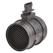 maf ignition on readings: 11.99, 0.01, 4.97, 4.97
engine running readings: 13.92, 0.00, 4.96, 4.96
As you can see in the pictures, the connection ports are wide, there are 4 prongs in each port.
And the throttle position sensor readings are:
Ignition on: 12.06, 0.01, 4.97, 0.01
engine running: 14.10, 0.00, 4.96, 3.26
Can you get any information from that? It seemed that wire with the bouncing readings was an earth, only it gets voltage running through it when the engine runs and there already appears to be an earth on that socket, I'm guessing by the readings on the other sensors it should probably read 4.97 or something similar
maf ignition on readings: 11.99, 0.01, 4.97, 4.97
engine running readings: 13.92, 0.00, 4.96, 4.96
As you can see in the pictures, the connection ports are wide, there are 4 prongs in each port.
And the throttle position sensor readings are:
Ignition on: 12.06, 0.01, 4.97, 0.01
engine running: 14.10, 0.00, 4.96, 3.26
Can you get any information from that? It seemed that wire with the bouncing readings was an earth, only it gets voltage running through it when the engine runs and there already appears to be an earth on that socket, I'm guessing by the readings on the other sensors it should probably read 4.97 or something similar
