MFI relay system from under hood fuse box?

2008 MITSUBISHI ECLIPSE
161,000 MILES • 2.4L • 4 CYL • 2WD • AUTOMATIC
Avatar
MILLER007
  • MEMBER
  • 3 POSTS
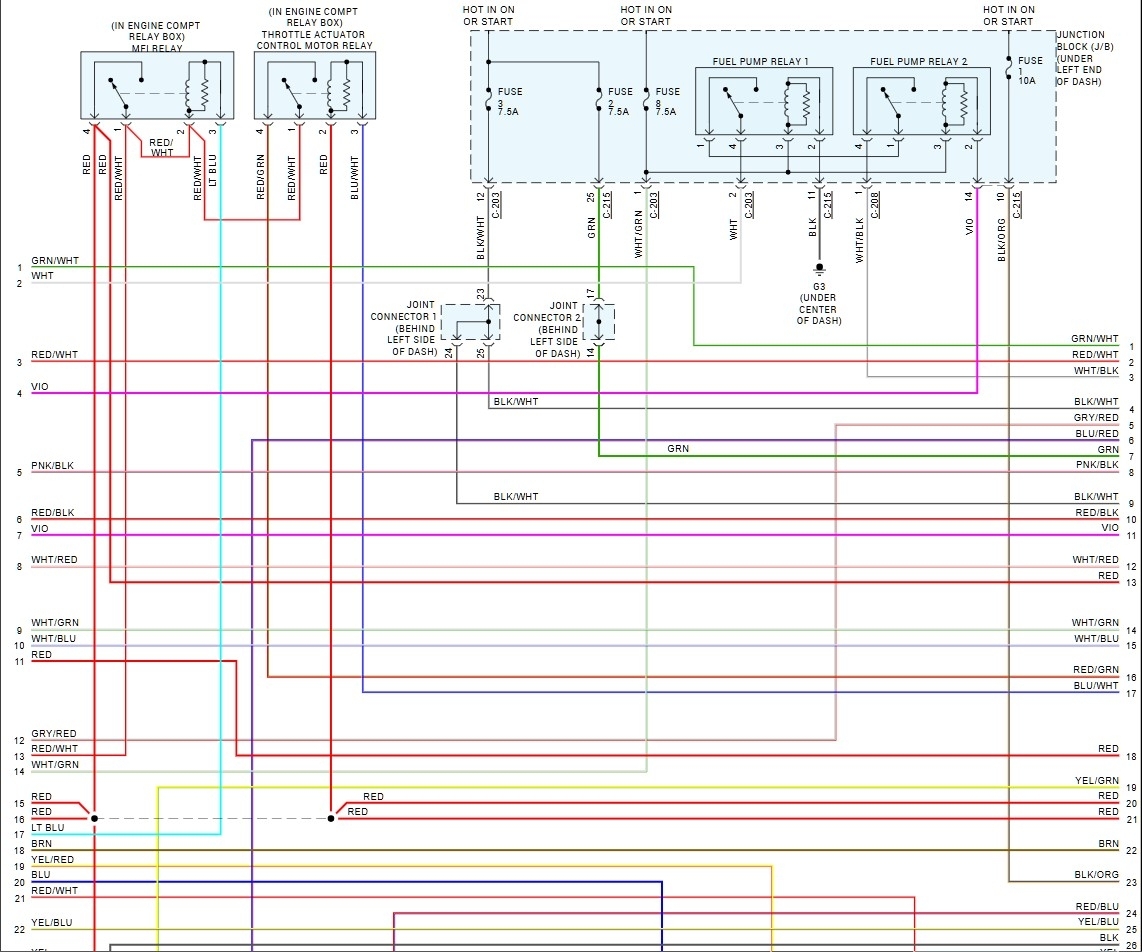
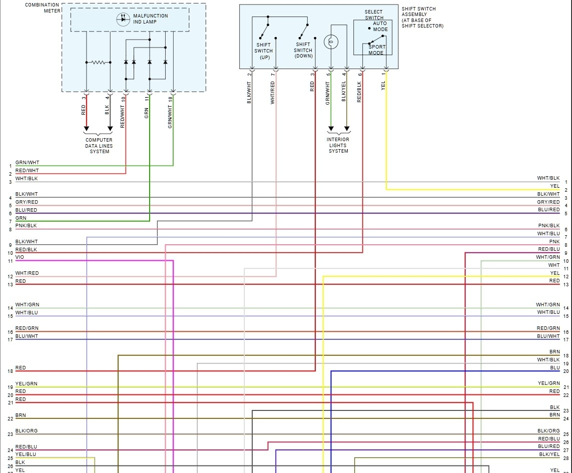
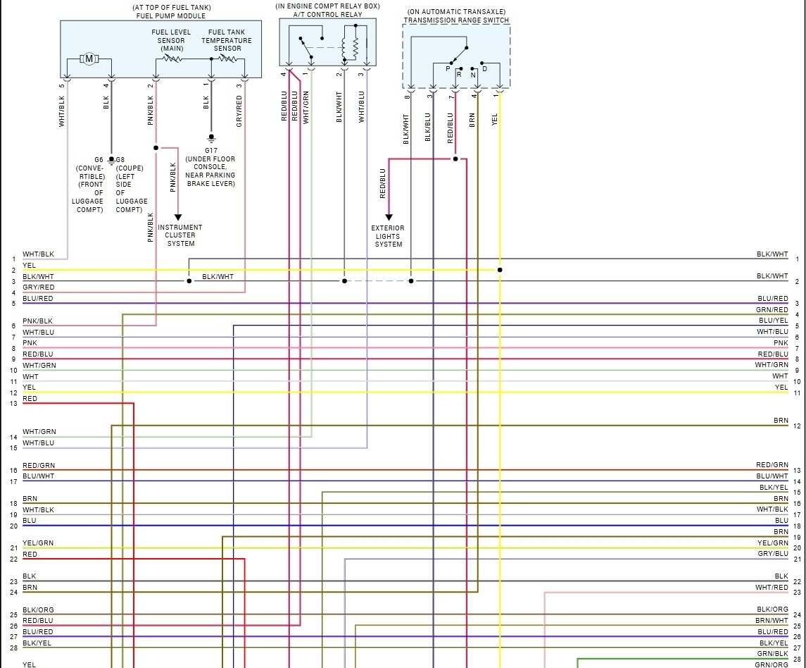
Having a issue with wiring a 4pin relay for my AT relay, plus my starter relay, MFI relay, actually it's the actuator thats a problem, might be that my trigger grounds are causing my relay to not switch over for power output , especially the thin green wire and the two spliced together purple with yellow stripe to my air conditioner
Apr 2, 2026 at 6:58 PM
Advertisement
Avatar
AL514
  • CERTIFIED EXPERT
  • 5,464 POSTS
Hello, is the vehicle a No Crank situation right now? Ill pull the wiring diagrams for those circuits.
Apr 5, 2026 at 11:50 AM
Avatar
MILLER007
  • MEMBER
  • 3 POSTS
Number 1 and 4 coils aren't firing, my signal wires are good , has ground and a 12volt reference at the connector, coils are good, just changed the crankshaft sensor but not getting a 5volts from the signal wire, the n ignition and the crankshaft sensors are giving me at least a 0.54 from the signal wire which is low, my relays are hooked up right , must have a short in my signal wire coming from. my ECM,,might need to clean my chassis grounds to see if its interfering with my signal grounds going to the sensor and to my ECM ground,a little help to find the solution
Apr 5, 2026 at 12:07 PM
Advertisement
Avatar
AL514
  • CERTIFIED EXPERT
  • 5,464 POSTS
Ok thanks for the additional info. Im just looking over the service info here real quick,
So you do have spark on the #2 and the #3 coils? I do notice that the number 2 & 3 coil share a Ground, while the #1 and #4 show each coil running its own ground wire.
As for the cam and crank sensors, how are you checking the signal? Are you using an oscilloscope?
Apr 5, 2026 at 12:29 PM
Avatar
AL514
  • CERTIFIED EXPERT
  • 5,464 POSTS
This is a wiring diagram of the ignition coils, but Im going to check the oem diagrams as well.
Apr 5, 2026 at 12:31 PM
Avatar
AL514
  • CERTIFIED EXPERT
  • 5,464 POSTS
If you suspect the crank signal wire is shorted to ground somewhere, unplug the sensor, Key Off, and see if you have continuity to ground (path to ground, very low resistance to ground), even with the ECM still plugged in the signal wire should be isolated from a direct path to ground.
If youre unsure, unplug the sensor and ECM so that signal wire is completely isolated from everything.
And where did the new crank sensor come from?
Apr 5, 2026 at 12:46 PM
Avatar
AL514
  • CERTIFIED EXPERT
  • 5,464 POSTS
These are the ECM wiring diagrams, the first and second are page 1, top and bottom, etc.
Let me know what you find, if you are getting spark from 2 out of the 4 coils and if youre only checking the crank signal with a multimeter, you will only see an average voltage at whatever speed the multimeter can grab a measurement. Thats why I would be scoping the sensors to get a visual of what they are doing.
Apr 5, 2026 at 12:53 PM
Avatar
AL514
  • CERTIFIED EXPERT
  • 5,464 POSTS
The oem wiring diagrams show the same wire colors, so thats correct.
Apr 5, 2026 at 1:03 PM