This G6 GTP 3.9 Transmission FR3 4T65E version has been registering ISS p0717 code for almost 2 years with no symptoms that the driver could detect. The ISS was replaced but that didn't erase the code. Recently, the TCM was replaced and programmed: Still no change. This past week, the 49-Way connector and wires to the TCM were replaced by splicing. The code p0717 was registered again. Finally- 2 days ago, the 20-Way external connector and wires to the transmission harness were replaced by splicing as well. When the job was done, everything was put back together except the Electronic Brake Module Connector was left unplugged *by mistake* as the car was being tested and the Key left in the run position for sometime. Later on, the connector to the EBCM was reconnected while the key was still in the run position and the scanner connected to the DLC *again, I think the key should've been turned off while reconnecting the electronic brake module.* The scanner initially displayed a message: "Communication with the Body Control Module was Lost." No code was registered. The car was taken for a drive cycle and the check engine light was actively cleared. Few minutes into the drive, the following occurred:
1. Code: p2534 Ignition switch/run low voltage
2. P0700 transmission
3. P0300 misfire
4. Check engine light blinking (not solid)
5. Acceleration began to suffer
6. Louder than normal noise
All spliced wires were rechecked for continuity.
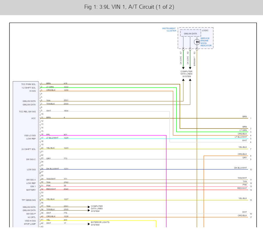
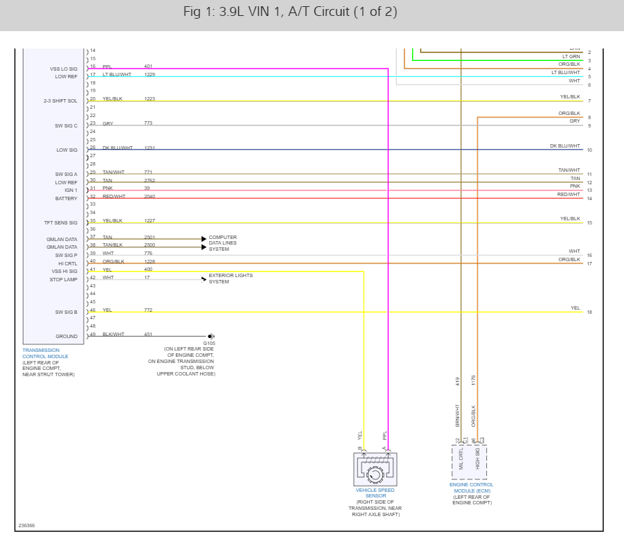
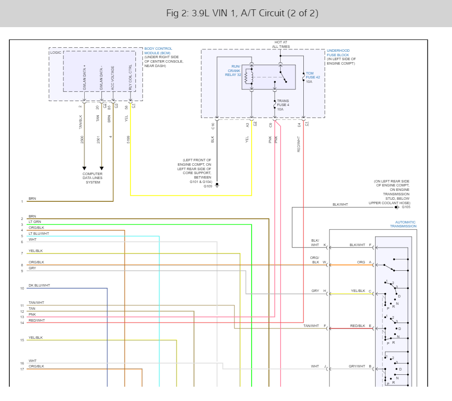
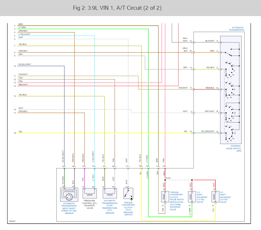
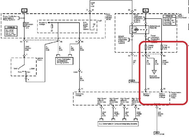
What happened? The ignition wire (pink circuit 1339 or simply 39) from TCM 49-way connector pin 31 to transmission harness 20-way connector pin E showed no continuity. Is this normal when the key is in the off position? Does this wire go through a fuse or fusible link? The wiring diagram shows transmission fuse 4 in the junction block but no fusing in the wire in between pin 31 and pin E unless I am not reading the diagram correctly. All other connections showed continuity
I am not sure if I should test while the engine is running or while the key is in the on position or for that matter while battery voltage and ground are connected. Could this be a simple splicing issue or more? I think the misfire is the result of low voltage rather than damage to ignition switch probably caused by ignition wire or ground issue assuming the EBCM incident was not significant. Before asking this question, I looked over and reviewed the pins, the wires and circuits related to the TCM-49 way, the 20-way AT harness, the BCM and the ECM. So, I should be able to follow advice. However, there is one part of the ignition circuit where the 31 pin at the TCM connector and the E-pin at the 20 way AT harness connector and the Junction block fuse 4 circuits that remains a bit unclear. I am thinking this is where the problem is. I attached the electrical diagram I had and circled the part that I am not sure about how to test.
James
1. Code: p2534 Ignition switch/run low voltage
2. P0700 transmission
3. P0300 misfire
4. Check engine light blinking (not solid)
5. Acceleration began to suffer
6. Louder than normal noise
All spliced wires were rechecked for continuity.
What happened? The ignition wire (pink circuit 1339 or simply 39) from TCM 49-way connector pin 31 to transmission harness 20-way connector pin E showed no continuity. Is this normal when the key is in the off position? Does this wire go through a fuse or fusible link? The wiring diagram shows transmission fuse 4 in the junction block but no fusing in the wire in between pin 31 and pin E unless I am not reading the diagram correctly. All other connections showed continuity
I am not sure if I should test while the engine is running or while the key is in the on position or for that matter while battery voltage and ground are connected. Could this be a simple splicing issue or more? I think the misfire is the result of low voltage rather than damage to ignition switch probably caused by ignition wire or ground issue assuming the EBCM incident was not significant. Before asking this question, I looked over and reviewed the pins, the wires and circuits related to the TCM-49 way, the 20-way AT harness, the BCM and the ECM. So, I should be able to follow advice. However, there is one part of the ignition circuit where the 31 pin at the TCM connector and the E-pin at the 20 way AT harness connector and the Junction block fuse 4 circuits that remains a bit unclear. I am thinking this is where the problem is. I attached the electrical diagram I had and circled the part that I am not sure about how to test.
James
Image (Click to enlarge)
Jun 23, 2021 at 1:18 AM