Low beam headlights not working

2003 JEEP LIBERTY
114,000 MILES • 3.7L • V6 • 2WD • MANUAL
Avatar
DINESH GOSAIN
  • MEMBER
  • 75 POSTS
The low headlights don't work, high beam works fine, bulbs are good, the fuses for low beams are not lighting up with the probe. also swapped relay switch.
Jun 9, 2022 at 9:57 AM
Advertisement
Avatar
BORIS K
  • CERTIFIED EXPERT
  • 836 POSTS
Hello,

The low beam relay is powered by fuse 15, 50A, in the power distribution center (PDC).
Constant 12V is transmitted on the red/tan wire to pin 1 at connector C3.
See image 1 below.
The first thing to check is if the horn is working as the horn fuse and relay are also powered by the same fuse, see image 2 below.
If the horn is working, provided you are still using the factory horn, then the next thing to check would be if you have constant 12V at terminals 30+86at the low beam relay socket.
This can be done using either a test light or a voltmeter.

https://www.2carpros.com/articles/how-to-use-a-test-light-circuit-tester
and
https://www.2carpros.com/articles/how-to-use-a-voltmeter

If 12V is present at both terminals then next check if a ground is switched on when the headlights are switched on at terminal 85, see image 1 below.

Next check continuity from relay terminal 87 to either fuse F4 or F5, see image 3 below.
This can be done using a voltmeter, digital multimeter.

https://www.2carpros.com/articles/how-to-check-wiring

Hope this helps.

Cheers, Boris
Jun 10, 2022 at 1:06 AM
Avatar
DINESH GOSAIN
  • MEMBER
  • 75 POSTS
In my Haynes book for the vehicle listed above I found the wiring schematics on page 12-8. Wiring charts are very intimidating and very, very hard to understand. I followed the first diagram and checked fuse 15 and 50 in the fuse box under the hood.
Actually, I pulled out all the mini fuses and checked to see if any were blown. They were all good. Then I checked the other fuse 50 and it looked fine also. It did not look blown. I decided to swap the fuses with other fuses, and no change.

My test light is the same as yours in one of the photos. I also used a voltmeter. I had jerry-rigged the wires to have a low beam. I took the low beam light wire and removed it from the bulb socket, and I put the high beam wires in the low beam in the bulb socket. It works, but I have to get my car inspection this month and I don't think this is going to work. The fuses 4 and 5 for the low beam still don't light up with the probe. So, fuses 4 and 5 show now activity. I had mentioned in my first post that I had swapped the relay switches. So, the switch makes a clicking noise and we know both high and low beam switches work. I don't have power to the low beam fuses and when the low beam wire was checked at the bulb socket wire. This is the only car I have to drive and I can't drive at night.

Please, please help me.
Dinesh
Jun 13, 2022 at 2:15 PM
Advertisement
Avatar
BORIS K
  • CERTIFIED EXPERT
  • 836 POSTS
Hello,

Just to clarify, when you switch on the low beam lights the low beam relay clicks.
If so, then there seems to be an internal failure in the junction block.
As a last try you could bridge the low beam relay terminals 30+87, with the low beams wired up as original the low beams should work, meaning fuses 4+5 will have power. If there was still no power this would definitely point to an internal junction block failure.

Cheers, Boris
Jun 14, 2022 at 12:28 AM
Avatar
DINESH GOSAIN
  • MEMBER
  • 75 POSTS
Hello Mr. Boris,

I tested the low beam relay out of the junction box and listened very carefully for the click sound which opens and closes the relay. You know I swapped the relays from high to low and low to high. I put the high beam relay in the low beam relay position and i took the low beam relay and put it in the high beam relay. When I turned on the lights, no low beam, when I turned on the fog lights they came on and when I turned on the high beam lights they worked. This means the relays are not the issue??? I don't know. I think you can answer that better. I'm going to go out to the car and start from the beginning again. I haven't looked up the ground for the wiring harness yet. I don't know where that would be.
Jun 14, 2022 at 6:10 AM
Avatar
DINESH GOSAIN
  • MEMBER
  • 75 POSTS
Mr. Borins K,

Since I'm going to start from the beginning, I was wondering you could provide the steps I should take from 1?
Jun 14, 2022 at 7:16 AM
Avatar
BORIS K
  • CERTIFIED EXPERT
  • 836 POSTS
Hello,

First ensure that you have constant 12V at terminals 30+85. Check this by using either a test light or a voltmeter with the low beam relay removed.

How to use a voltmeter:
https://www.2carpros.com/articles/how-to-use-a-voltmeter

The ground is switched by the body control module at terminal 86 at the low beam relay socket. The easy way to test this is to use a test light connected to 12V (battery positive) and touch terminal 86 with the relay removed. Switch the low beam lights on and the body control module should switch a ground to this terminal and the test light will light up.

How to use a test light:
https://www.2carpros.com/articles/how-to-use-a-test-light-circuit-tester

To test the integrity of the internal circuit of the junction block I would suggest to bridge terminal 30 with 87. This in turn should energize both fuse 4+5 and light up the low beam lights.

See illustration below.

Hope this helps.

Cheers, Boris
Jun 14, 2022 at 8:54 AM
Avatar
DINESH GOSAIN
  • MEMBER
  • 75 POSTS
In my Haynes book for the vehicle listed above I found the wiring schematics on page 12-8. Wiring charts are very intimidating and very, very hard to understand. I followed the first diagram and checked fuse 15 and 50 in the fuse box under the hood.
Actually, I pulled out all the mini fuses and checked to see if any were blown. They were all good. Then I checked the other fuse 50 and it looked fine also. It did not look blown. I decided to swap the fuses with other fuses, and no change.

My test light is the same as yours in one of the photos. I also used a voltmeter. I had jerry-rigged the wires to have a low beam. I took the low beam light wire and removed it from the bulb socket, and I put the high beam wires in the low beam in the bulb socket. It works, but I have to get my car inspection this month and I don't think this is going to work. The fuses 4 and 5 for the low beam still don't light up with the probe. So, fuses 4 and 5 show now activity. I had mentioned in my first post that I had swapped the relay switches. So, the switch makes a clicking noise and we know both high and low beam switches work. I don't have power to the low beam fuses and when the low beam wire was checked at the bulb socket wire. This is the only car I have to drive and I can't drive at night.

Please, please help me...
Dinesh
Jun 14, 2022 at 11:24 AM (Merged)
Avatar
JACOBANDNICKOLAS
  • CERTIFIED EXPERT
  • 110,175 POSTS
Hi,

Power to both fuses 4 and 5 comes from fuse 15 (50 amp). However, for the power to reach fuses 4 and 5, it must pass through the low beam relay. Have you checked the relay? If not, remove the low beam relay and switch it with a different relay from the box having the same part number. If there isn't one, here is a link that explains how to test a relay.

https://www.2carpros.com/articles/how-to-check-an-electrical-relay-and-wiring-control-circuit

I attached the schematic I have below. If you have questions about it, let me know what they are. Also, keep in mind, if fuse 15 is good, power is there at the relay. For the switch in the relay to close and send power to fuses 4 and 5, a ground path has to be provided to the primary side of the relay by the body control module. We could have an issue there as well. I highlighted the BCM wiring, and I placed an arrow showing the power flow from fuse 15.

I will watch for your reply.

Take care,

Joe

See pics below.
Jun 14, 2022 at 11:24 AM (Merged)
Avatar
DINESH GOSAIN
  • MEMBER
  • 75 POSTS
I tested the low beam relay out of the junction box and listened very carefully for the click sound which opens and closes the relay. You know I swapped the relays from high to low and low to high. I put the high beam relay in the low beam relay position and i took the low beam relay and put it in the high beam relay. When I turned on the lights, no low beam, when I turned on the fog lights they came on and when I turned on the high beam lights they worked. This means the relays are not the issue??? I don't know. I think you can answer that better. I'm going to go out to the car and start from the beginning again. I haven't looked up the ground for the wiring harness yet. I don't know where that would be.

Jun 14, 2022 at 11:24 AM (Merged)
Avatar
DINESH GOSAIN
  • MEMBER
  • 75 POSTS
Hello Mr. Boris,

Ah, when I said that I heard the click on the relay I would disregard that. Sorry about that. I removed the low beam relay from underneath the dash. I followed your instructions to test the relay "First ensure that you have constant 12V at terminals 30+85. Check this by using either a test light or a voltmeter with the low beam relay removed." I used two different voltmeters and I got 000 not 12V. Perhaps I did this wrong. Terminal 86 did not light up either with light tester connected to the positive terminal of the battery. I also pulled out the high beam relay to perform the same test on that and I got nothing on that relay as well.
Jun 14, 2022 at 1:30 PM
Avatar
DINESH GOSAIN
  • MEMBER
  • 75 POSTS
Mr. Boris,

I've attached some pics so you would know what I'm
looking at. I pray this helps you.

Thank you,
Dinesh
Jun 15, 2022 at 3:53 AM
Avatar
DINESH GOSAIN
  • MEMBER
  • 75 POSTS
Joe F,

I've attached some pics so you would know what I'm
looking at. I pray this helps you.

Thank you,
Dinesh

Jun 16, 2022 at 10:29 AM
Avatar
DINESH GOSAIN
  • MEMBER
  • 75 POSTS
I installed a new relay and no low beam lights. Fuses 4 and 5 do not light up. Boris, I don't know how to do what you're asking. To test the integrity of the internal circuit of the junction block I would suggest bridging terminal 30 with 87. This in turn should energize both fuse 4+5 and light up the low beam lights. Yeah, I don't how to do what you're asking? Bridge terminal 30 with 87. I don't understand that. My low beam wire is purple in color on the driver's side. They seem to be routed to the front of the car.
Jun 16, 2022 at 1:50 PM
Avatar
CARADIODOC
  • CERTIFIED EXPERT
  • 34,306 POSTS
Allow me to add a comment here. If someone asked you to bridge, or jump a relay, they mean use a piece of wire or a stretched-out paper clip to connect the two terminals for the relay's contacts. You're doing manually what relays do when they're energized. That powers up the circuit to allow you to work on it or take voltage readings.

When you poke anything into the terminals in the socket, be careful to not use anything fat enough to stretch those terminals. That can lead to intermittent problems later.

The relay in the top left of this drawing is the most common one used in Chrysler products. The others I drew here were also used in some models.
Jun 16, 2022 at 8:10 PM
Avatar
DINESH GOSAIN
  • MEMBER
  • 75 POSTS
Thank you, Randy B, in your drawing I have the middle 5pin relay. I think there's an image of the relay i have forwarded. So put a paper clip in the two terminals 30+85 to see if i get a 12V on a probe that lights up and then check to see if fuses 4 and 5 light up in the fuse panel.

I didn't mention this earlier, because I didn't think that the radio would cause my low beam lights not to work. The radio has gotten old, and I thought it went out. All the fuses for the radio are in different places, not with any light system fuses.
Jun 17, 2022 at 2:38 PM
Avatar
CARADIODOC
  • CERTIFIED EXPERT
  • 34,306 POSTS
If you have the skinnier relay in the top middle of my drawing, jump the two larger terminals with the arrows pointing to them.

When a relay has terminals designated as "85" and "86", those or for the coil that activates the relay. "87" and "30" are for the relay's contacts, meaning the switch part of it. That's what we need to jumper to in effect, turn the switch on.
Jun 17, 2022 at 2:45 PM
Avatar
DINESH GOSAIN
  • MEMBER
  • 75 POSTS
so, 30+85 like in the photo below and you said 87+30. Two different connections.
Jun 17, 2022 at 3:54 PM
Avatar
CARADIODOC
  • CERTIFIED EXPERT
  • 34,306 POSTS
I don't know where the confusion came from, but terminal 85 is not part of this story. That's in the control circuit as one of the two terminals for the relay's coil. It's 30 and 87 you want to jump together.

As a point of interest, and to confuse you even more, when the relay in your drawing is not energized, terminals 87A and 30 are connected internally. That condition, meaning terminal 87A, is rarely used in any car model. Many relays don't even have terminal 87A. They have just four terminals. When the coil is energized by putting 12 volts across it, the relay's movable contact flips. It leaves 87A and makes contact with terminal 87. That is the standard relay function used almost all of the time.
Jun 19, 2022 at 7:19 PM
Avatar
DINESH GOSAIN
  • MEMBER
  • 75 POSTS
Hello Randy,

Over the weekend I removed the plastic cover to the relay and tested it with a 12v battery from one of my cordless drills. As I witnessed the relay click and move. I have a new relay that I purchased last week and installed it in my car. Even with a new relay the low beams don't come on... I was hoping that the new relay installed would fix it, but it didn't. I don't know what to do now. Any assistance would be appreciated.
Jun 20, 2022 at 10:48 AM
Avatar
DINESH GOSAIN
  • MEMBER
  • 75 POSTS
I just checked with a power tool battery and jumped 30+87, 30+87A and no clicks on the relay. I only get a relay click on 85+86. Nothing else gives me any clicks. This is the original relay from the car. I have a new relay in the car for the low beams and they still don't work. Even with the new relay fuse 4 and 5 don't light up.
Jun 20, 2022 at 1:02 PM
Avatar
DINESH GOSAIN
  • MEMBER
  • 75 POSTS
Hello Randy,

Okay, I just used my craftsman 19.2v battery to check the relay pins.

Ok, 30+87 19V then drops to 1
30+85 = same as above
87+87A = same as above
87+86 = low voltage, I saw 4.5 then drop to 1
85+86 = the relay clicks
does this mean the relay is good?

I just received my relay tester that I bought, and I tested the old relay and the new relay. They both worked on the tester.

Thank you,
Dinesh
Jun 21, 2022 at 11:46 AM
Avatar
CARADIODOC
  • CERTIFIED EXPERT
  • 34,306 POSTS
If a relay is suspect, we just switch it with a different one like it. There's typically only two or sometimes three different styles of relay in any under-hood fuse box. With current labor rates, we can't justify testing parts when customers are paying us by the hour.

I'm not familiar with relay testers, so I don't know how they work to determine if one is good, but I do have one comment of value for you to add to your memory banks. All relays will have two terminals for their coil of wire inside, and on their own, they are interchangeable. On Chrysler diagrams, they designate them as terminals "85" and "86" on most models. Where the potential problem comes in is every coil of wire that is energized creates a magnetic field around it. That's how starter motors, generators, and relays work. When the coil is turned off, the magnetic field is forced to decay instantly. That "induces" a huge reverse voltage spike that could go as high as 300 volts. In some applications that is desirable, particularly with ignition coils. We use that spike to develop the voltage for the spark plugs. In relays, those voltage spikes can do damage to the circuitry controlling them. To prevent that, most relays have a diode added internally between terminals 85 and 86. A diode is a one-way valve for electrical current flow. It's placed in there backward so in effect, it's like it isn't even there when the relay is activated. It's when the relay is turned off and that spike occurs that the diode acts like a piece of wire and shorts out that spike. It's because of that diode that terminals 85 and 86 can't be interchanged. Terminal 86 gets the 12 volts, whether it's constant or switched on and off, and terminal 85 is the ground terminal, again, regardless if it's switched on and off or is there constantly. If you want to test the operation of a relay's coil and you aren't sure if it has a diode inside, or you don't know which terminal needs the positive and negative connections, use a small 12-volt light bulb in one of the test leads. If you connect the battery with the correct polarity, the relay will click and the bulb might glow just enough for you to see it. If you connect the battery backward, the relay's diode will act as a short circuit, but the light bulb will limit current to a safe level and will be normal, full brightness. That will prevent melted wires or burned fingers. This procedure is much easier to do that it is to describe, so I put together a little drawing. Any 12-volt light bulb will work. I like to use 3157 brake light bulbs because it's easy to connect clip leads to them. That bulb will allow a maximum of one amp of current flow when connected to a 12 volt battery. Even if you use a 20-volt battery from a power tool, the bulb will be brighter if the wrong wires are hooked to the relay terminals, but current will still be limited to a safe level.

Many relays commonly found in GM vehicles use a resistor instead of a diode for the same purpose. Resistors are less effective, but effective enough to dampen the voltage spikes. The advantage is since resistors don't have a polarity, the two terminals for the coil can be interchanged.
Jun 21, 2022 at 6:43 PM
Avatar
DINESH GOSAIN
  • MEMBER
  • 75 POSTS
Thank you, Randy. I have a 5-pin relay, so your drawing is great, but I can't get the bulb to light up or relay to work. I can follow directions from start to finish. thanks. I see that the blue wire is going to the + 18V on the battery. The green wire connects to a pin on the relay, don't know which pin because I have 5 pins on my relay. Then the pink wire is going to the - terminal on the battery and the other end is connected to the relay. I don't know which pin?
If I'm looking at my drawing of the relay 30+87 are now connected. So, I have 86, 87A, and 85 left.

I just want to drive my car...thanks again.
Jun 22, 2022 at 10:07 AM
Avatar
CARADIODOC
  • CERTIFIED EXPERT
  • 34,306 POSTS
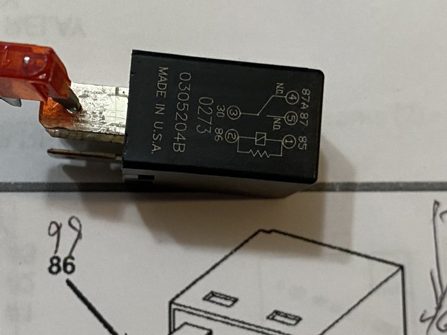
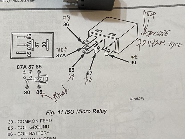
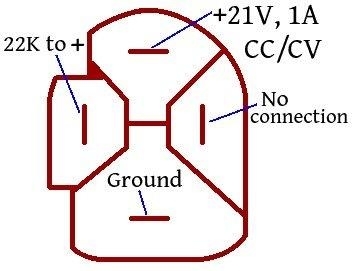
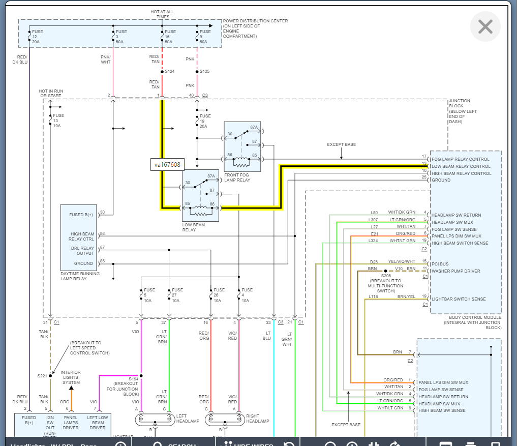
Terminal 87A is in the middle. It has no place whatsoever in this story, so don't worry about that one.

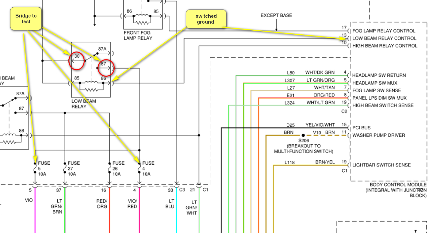
You're trying to test a relay, but there's actually two parts to it. Testing the coil is the first part of that. You were correct to use a battery to power the coil, but the confusion comes from knowing which terminals to use, hence my sad drawing. With a simple, basic relay, the coil of wire has two ends with two corresponding terminals. We can measure it with an ohm meter, or we can use the battery, then feel and listen for the click. With this basic relay coil, the positive and negative can be applied to either terminal.

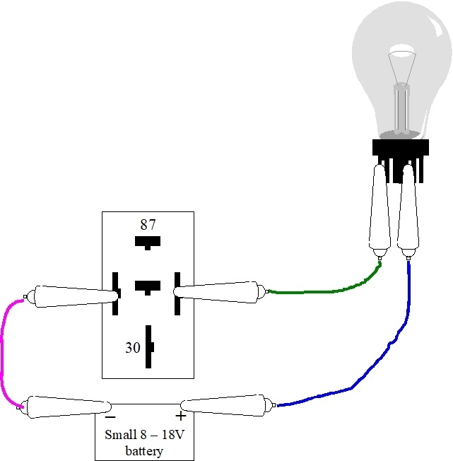
I described the use of a diode across the coil to dampen the inevitable reverse voltage spike that always occurs the instant current flow through the coil is stopped. That diode is the only reason the positive and negative must be applied to the right terminals. All you have to do with your battery is connect the positive post to terminal 86 on the relay, and the negative post to terminal 85. I added those numbers to the drawing below. If the coil is good, you'll hear and feel the click inside the relay.

My only reason for adding the light bulb is for those times you don't know which terminals to use. This way, one of three things will happen:

1. No connection, no current flow, the bulb is off.
2. Proper connection, current flow limited by the bulb's resistance, bulb is dimmer than normal.
3. Solid connection, current flow is limited by the bulb's resistance, bulb is full brightness.

A solid connection is the same as if you connected the pink and green jumper wires together. If the bulb wasn't there, you'd have nothing to limit current flow. The jumper wires would smoke and melt, and you'd burn your fingers. We need something to limit current. The bulb does that while at the same time giving us a nifty visual indication of how much current is flowing.

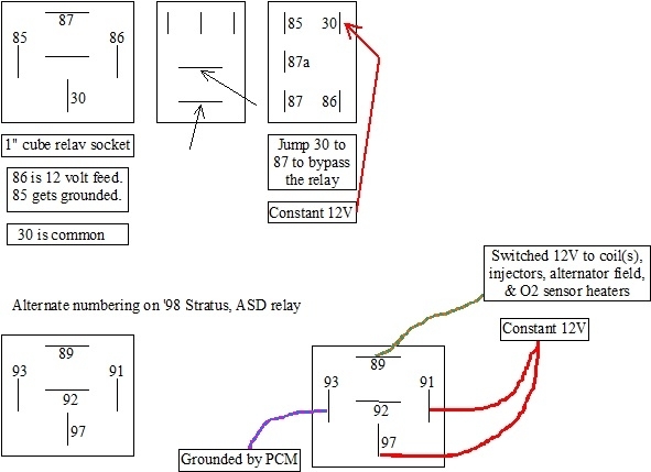
Almost as bad as a solid connection is when the positive is applied to terminal 85, and the negative to terminal 86. Remember, that would work normally for the basic relay, but we have a diode in your relay. With this reversed connection, that diode will act like a piece of wire, or dead short. There's nothing to limit current flow, so again, the jumper wires would melt and smoke. The diode can't handle that high current so it will short. At that point the relay will never work, even when connected correctly. To prevent that, we add the light bulb. If you connect terminals 85 and 86 backward, the bulb will be full brightness and limit current flow to a safe level. More importantly, there will be no click in the relay. You can switch the jumper wires, then the relay will click since no damage occurred to it. By using the light bulb, you can place the jumper wires on any terminals until you find the two that activate the relay. You don't have to know anything about it as far as which terminal is which.

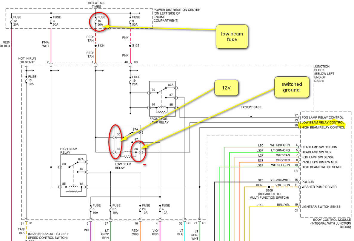
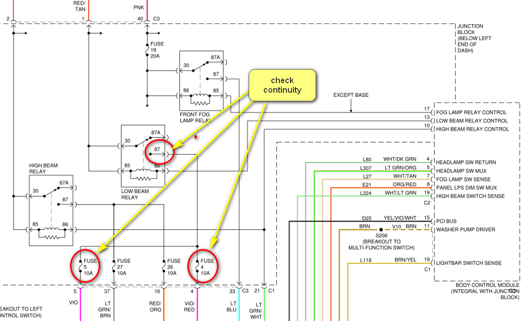
The second part of testing a relay has to do with the high-current contacts. Those are turning on, meaning connecting terminals 30 and 87 together when the click occurs. At this time, you can use an ohm meter to check if the connection occurred. The ohm meter's reading will change from "open circuit", or infinite, to close to 0 ohms. There's always some resistance in the meter's leads, so a reading of as much as 5 - 10 ohms is normal. The problem with this test method is it doesn't require the contacts to pass very much current. They may be able to pass the few milliamps from the ohm meter, but not the 10 to 30 amps needed by the horn, radiator fan, or fuel pump motor. Every time a high-current circuit is switched off, an arc occurs when the contacts separate. Over time that arcing prevents a nice solid connection from occurring. It's also not uncommon for moisture to get inside the relay and corrode the contacts.

All of this testing is fine when we're learning how relays work, but it's not practical to diagnose a problem this way. The fastest and most effective way we do this is to first place a finger on it, then have a helper turn on the switch that activates that relay. If we feel the click, we know the coil is good, and everything that controls that relay is working. That entire half of the system is done.

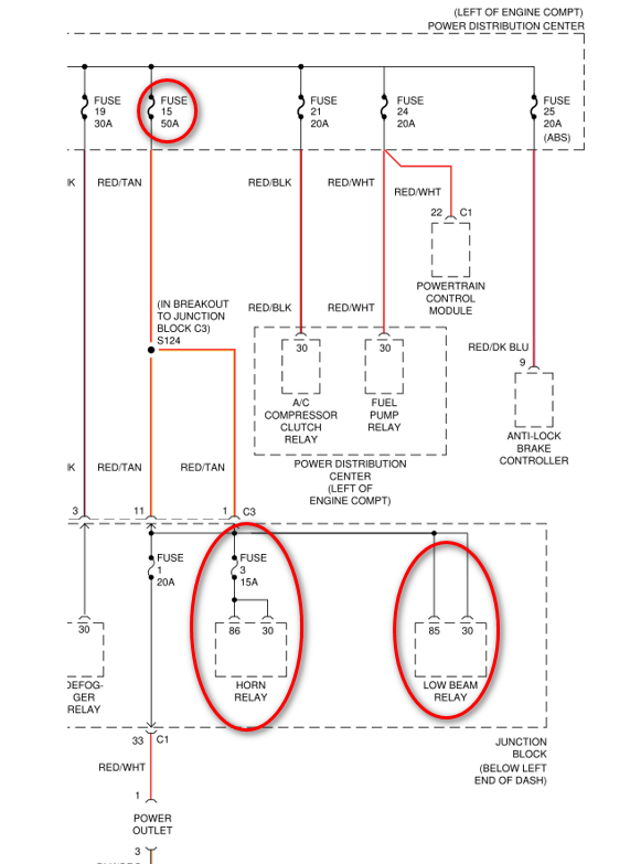
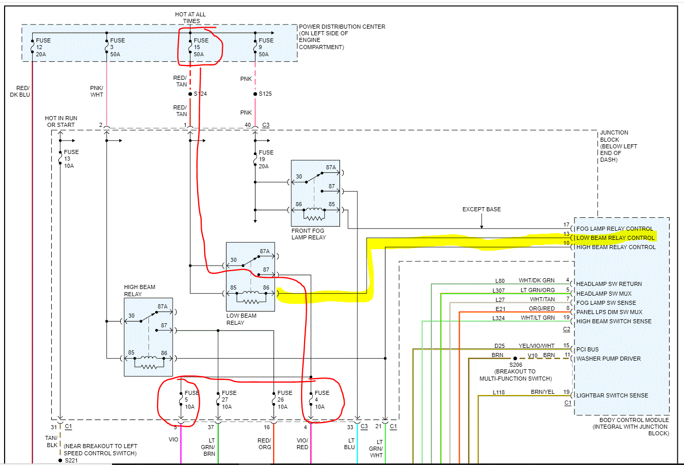
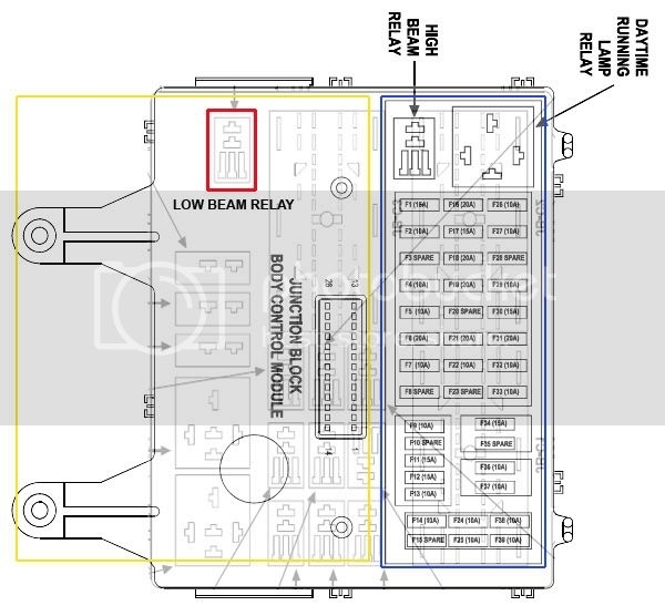
For the high-current half of the system, the first step is to remove the relay, then check for 12 volts always on terminal 30. If that's there, and the relay clicks, the last step is to check for 12 volts appearing on the circuit under test. For example, for a dead head light circuit, we'd check for 12 volts at the plug for one of the head lights. If it's not there but every other test was good, we'd suspect the contacts in the relay are arced or there's a break in the wire leaving terminal 87. The next step would be to substitute a different relay as a test. There's almost always up to a half dozen identical relays used for different circuits. There's one for the AC compressor clutch, one or two for the wipers, one for the fuel pump, etc. Any of those can be used. If that gets the system working, it's pretty obvious the relay was defective and must be replaced. If that doesn't get the system working, we know the problem lies further down the circuit, so we'd follow that wire to the next test point.

Hope that clarifies the issue. Hit me with your next question.
Jun 22, 2022 at 2:32 PM
Avatar
DINESH GOSAIN
  • MEMBER
  • 75 POSTS
Hello Randy,

I can't thank you enough for all your assistance. You're great. I'm quite sure that I followed the instructions you provided above. I used your diagram setup. I attached one alligator clip to positive and then to negative on the battery. Then I attached two leads to the bulb.
Then I attached the battery to the bulb lead and the bulb lit up. I just wanted to see if it would light up. Then I attached the leads from the bulb to the relay as you mentioned above, "All you have to do with your battery is connect the positive post to terminal 86 on the relay, and the negative post to terminal 85. I added those numbers to the drawing below. If the coil is good, you'll hear and feel the click inside the relay." The bulb lit up and relay was clicking. So, this means that the relay is good, and my 7440 bulb is good. I used this "7440" bulb because that's i had. Now how do I get the my low beams to work???

Thank you,
Dinesh


P.S. Just for giggles where exactly is the low beam relay located?
Jun 23, 2022 at 8:00 AM
Avatar
CARADIODOC
  • CERTIFIED EXPERT
  • 34,306 POSTS
The relay is in the lower right corner of the Junction Block, (inside fuse box).

I downloaded the front lighting diagrams. I'll have to study them and format them for uploading, if Boris K doesn't get back to you first.
Jun 24, 2022 at 8:25 PM
Avatar
DINESH GOSAIN
  • MEMBER
  • 75 POSTS
Randy, again thank you. I knew where the relay was but with my luck, I thought I should ask. I drove to a mechanics shop, someone I kind of know. I gave him all that I had done with you, and the rest of your team, and also mentioned that you guys are grate. You, at 2carpros.com are the only people that have helped me. I truly hope I never forget this site, and I will be passing the name onward.

I should have mentioned to you that I have really awful Karma... I've lived through so many things that go wrong that other people have their head scratching. "I've never seen that" Case in point my lights...

So, let's review what I've done:
1. Installed new relay and tested old relay for functionality.
2. The Bulbs are good.
3. I can duplicate the bulb test that you mentioned above.
4. "I not sure about this, talking a long shot but if my switch is bad it's going to take at least another function down as well.
5. Back to the scratching head issue, my backup lights stopped working. I replaced the bulbs, changed the relay, fuses were good, still nothing. I don't know where I read that for a manual transmission there is switch that goes directly into the transmission. I may have read it in the Hanes book. Change that $10.00 part and lights were working. A dealer wanted a lot of money.
6. I'm going to take the front grill off today and see where those light wires are going. I also checked the grounds. I found three, and they looked fine.
7. So, I still don't have low beams. Randy, I hope I can work with you. I'll let you know what issues I run into today.
8. How do you test a wire to see if it works? yeah, another dumb question.
I think I know how to do it, but i thought I ask. You take the light harness to the bulb off. Put the car in the on position, and turn the headlight on. Then at the head light wire harness, check to see if I'm getting 12V on the low beam wire. I also used a hanging clamp on that wire and got nothing.


Jun 25, 2022 at 6:52 AM
Avatar
CARADIODOC
  • CERTIFIED EXPERT
  • 34,306 POSTS
You have the right idea on checking for voltage on a wire, but here's a link to an article that explains more about wire testing:

https://www.2carpros.com/articles/how-to-check-wiring

Wire testing might be appropriate if the relay was turning on, but you didn't mention if you felt the click. If that relay is not turning on, we have to shift our attention to the Body Computer. Also, did you jump the two terminals in the relay's socket? The low beams should have turned on when you did that. If they did, we know the wiring has to be okay.
Jun 25, 2022 at 6:28 PM
Avatar
DINESH GOSAIN
  • MEMBER
  • 75 POSTS
Hi Randy,

I'm so sorry Randy, I haven't gotten back to you. Life got in the way, my brother got Coronavirus and my 82 year old mother fell outside of her house and broke her wrist. I will try to start where I left off and hopefully fix this because my inspection for the car ended yesterday. It's a bit hot outside, I'll wait until it gets a little cooler.
Jul 1, 2022 at 10:15 AM
Avatar
CARADIODOC
  • CERTIFIED EXPERT
  • 34,306 POSTS
No hurry. I run to town almost every day to read and post replies, so I'll be here to see what you come up with.
Jul 2, 2022 at 2:08 PM
Avatar
DINESH GOSAIN
  • MEMBER
  • 75 POSTS
Hello Randy,

Another hurdle Randy. I forgot to mention that my laptop went up in smoke early last week. I had just turned it on, and I saw smoke and burning electronic smell from the left side of the laptop. All my files regarding my car are on that laptop, among other documents. I’ve ordered parts for the laptop for repair. My main desktop machine got fried a few months ago. Bad Karma!!!
At least I have one computer working.

This is a copy of my battery’s pin outs that I’m using.
Jul 6, 2022 at 2:44 PM
Avatar
JACOBANDNICKOLAS
  • CERTIFIED EXPERT
  • 110,175 POSTS
Hi,

I noticed you haven't been contacted in a couple of days. Have you been able to make any progress? We're interested in knowing.

Let me know and let me know if I can help.

Joe
Jul 8, 2022 at 10:32 PM
Avatar
CARADIODOC
  • CERTIFIED EXPERT
  • 34,306 POSTS
Just got back to town. Was at the Iola Old Car show swap meet since Wed. My phone worked there for the first time, but this year I was surprised to find they discontinued their internet access. Sorry for the delay. Sorry to hear about you 'puters. I'm all too familiar with that frustration. I have four backups now on memory sticks.

I don't recognize your drawing. Is that related to your vehicle or your computer?

I'll be back tomorrow. Gotta continue to home to see if any of my cats passed out from starvation.
Jul 10, 2022 at 6:41 PM
Avatar
DINESH GOSAIN
  • MEMBER
  • 75 POSTS
Hello Randy and Joe,

Sorry about being out of commission all this time. Randy, i think you asked me what the pic was-it's for my craftsman 19V cordless battery drill. I'm going to go back and see where we left off. I think you wanted me to remove the relay in the car and test two connectors to see if there was any voltage. I forgot what pins they were, and low beams still don't work.

Thanks,
Dinesh
Sep 14, 2022 at 8:54 AM
Avatar
DINESH GOSAIN
  • MEMBER
  • 75 POSTS
I also checked the low beam relay, and it does click when I start the car, not when turning the key to the on position. Remember the old relay worked as well, even though I bought two new relays and a relay tester. Automotive relay tester (NCBJ-707). I can't believe that the relay tester actually worked for me.
Sep 14, 2022 at 12:22 PM
Avatar
DINESH GOSAIN
  • MEMBER
  • 75 POSTS
Low beams don't work even when i replaced the relay with a new relay today.
Sep 16, 2022 at 2:49 PM (Merged)
Avatar
KASEKENNY
  • CERTIFIED EXPERT
  • 18,907 POSTS
We need to start by checking the fuse for the low beams and making sure that is not an issue.

This is a 50-amp fuse and number 15 on the PDC in the engine bay.

https://www.2carpros.com/articles/how-to-check-a-car-fuse

If the fuse is ok, we need to go to the relay and remove it and check to find out if the BCM is grounding the relay so that it will turn the head lamps on.

You do this by putting a meter lead on battery positive and then the other on pin 86 and turn the headlights on. The meter should read 12 volts which will show the BCM is commanding the headlights on.

https://www.2carpros.com/articles/how-to-check-wiring

If it is, then jump the relay and make sure the head lamps actually come on.

Let's start with this and we can go from there.

Thanks
Sep 16, 2022 at 2:49 PM (Merged)
Avatar
DINESH GOSAIN
  • MEMBER
  • 75 POSTS
Hello Randy,

Over the weekend I removed the plastic cover to the relay and tested it with a 12v battery from one of my cordless drills. As I witnessed the relay click and move. I have a new relay that I purchased last week and installed it in my car. Even with a new relay the low beams don't come on. I was hoping that the new relay installed would fix it, but it didn't. I don't know what to do now. Any assistance would be appreciated.
Monday, June 20TH, 2022 AT 10:48 AM
Tiny
Dinesh Gosain

I just checked with a power tool battery and jumped 30+87, 30+87A and no clicks on the relay. I only get a relay click on 85+86. Nothing else gives me any clicks. This is the original relay from the car. I have a new relay in the car for the low beams and they still don't work. Even with the new relay fuses 4 and 5 don't light up.
Sep 16, 2022 at 2:49 PM (Merged)
Avatar
CARADIODOC
  • CERTIFIED EXPERT
  • 34,306 POSTS
We need to step back and take a breath, then start anew. After rereading the replies, some things came to light that I overlooked before. First, what you're doing with a battery is a huge time waster. There are easier and faster ways of approaching this. Next, I noticed at one point you were connecting the battery to terminals 30 and 87, then to 30 and 87A. Those are the switching contacts, not the coil that makes the relay click. When the relay is not energized, terminals 30 and 87A are connected internally and will short out your battery.

In the name of speed and efficiency, if you have any reason to suspect the relay, just switch it with one of the others like it. If the malfunctioning circuit works now, the removed relay is defective. If the circuit is still dead, it's not the relay and we can move on. The formerly suspect relay will work properly in the circuit you switched it to.

Once we know the relay isn't causing the problem, there's two circuits we have to look at. Terminals 85 and 86 are for the coil that energizes the relay. Put your finger on the relay, then have a helper turn on the lights. If you feel and hear the relay, click, we're done in that circuit. When multiple relays click on and off at the same time, you may need to remove the cover on the one you're checking, then watch if the movable contact moves when your helper turns on the switch.

If the relay clicks on and off at the appropriate times, we can move on to the switched side of the relay, meaning the two contacts, terminals 30 and 87. There's two quick tests for this circuit. The first is to check for 12 volts on terminal 30 in the relay's socket. That should be there all the time. A test light is the best tool for this test. Often these circuits are fused with a fuse link wire. Those can burn open, yet a digital voltmeter can falsely detect 12 volts that isn't really there. I can explain that further later, if needed. If those 12 volts are missing, check for it on terminal 87. That is customarily not the terminal that has the 12 volts applied to it, but the circuit can work that way. Double-check rather than overlooking something weird.

The other quick check is to just jump terminals 30 and 87 together in the socket, with a piece of wire or stretched-out cotter pin. That will energize the circuit just as if the relay had switched on. The circuit, the headlight in this case, should turn on now. If it doesn't, you can do the voltage tests along the circuit until you find where the 12 volts are being lost and not make it to the light. No need to have the relay installed and no need to turn on the light switch. This same procedure works for the majority of the other relay-switched circuits on the vehicle.

Once we know which circuit isn't working, we can look at the diagrams and figure out where to go next.
Sep 18, 2022 at 6:37 PM
Avatar
DINESH GOSAIN
  • MEMBER
  • 75 POSTS
Hello Randy,

I just checked with a power tool battery and jumped 30+87, 30+87A and no clicks on the relay. I only get a relay click on 85+86. Nothing else gives me any clicks. This is the original relay from the car. I have a new relay in the car for the low beams and they still don't work. Even with the new relay fuses 4 and 5 don't light up.

As of today, I reinstalled the relay under the dash and turned the key to the on position and felt the click on the relay.
Sep 21, 2022 at 8:14 AM