How to install a shut off switch in my pickup for anti-theft?

1996 CHEVROLET 1500
119,000 MILES • 4.3L • V6 • 2WD • AUTOMATIC
Avatar
BILL93240
  • MEMBER
  • 62 POSTS
Hello, I am planning to install a shut off switch in my pickup for anti-theft and would like some advice and ideas on wiring and also the best defeat measure. Also, the location of the switch. Thank you and I look forward to your reply. Regards, Bill
Jan 17, 2024 at 10:19 AM
Advertisement
Avatar
CARADIODOC
  • CERTIFIED EXPERT
  • 34,306 POSTS
Being a custom installation, you're asking for answers to questions we should be asking you. Where would you like to hide the switch? How would you like the switch to interrupt something? Some factory systems turn off the electric fuel pump. Some turn off fuel and ignition. An easy circuit prevents the starter motor from cranking the engine, but if defeated by jumping the starter relay, the engine can still be started, but with a little inconvenience. This would be necessary if the switch went bad, for example, but a thief would have to know to do that and take the time to go under the hood. He's likely to just move on.

To interrupt the fuel pump, ignition system, or starter, you can do any combination with one toggle switch that must be switched to the proper position to turn those systems off. This can also be done with multiple switches that must all be set to the correct positions. A common location is under the steering column on the left side so it's easy to reach just before you jump in. The drawback is it might get hit by your kneecap. If you're happy just disabling the starter, my preference would be to use a push button. Unlike the silly push buttons used the last few years by the manufacturers, this would be a switch that must be pressed with one hand while you turn the ignition switch with your other hand. That's a less common method and one a thief wouldn't think to look for. If you want to mount that switch under the dash where it's hard to see, that could imply to a thief that it's not meant to be seen or used while driving, so it's related to anti-theft. Instead, mount it up higher where a driver would have normal access to it, and label it "Train Horn". That accessory would also use a momentary switch, but it's not likely to be pressed by a thief experimenting with random add-on devices.

Another option for any combination of systems is to use three, four, or five switches in a row. Each one must be set to the correct position for the engine to crank and run. You can have one switch for each system, or all of the systems turn off if only one switch is set wrong.

If you want to get really complicated, consider a row of three or four push button switches, and only the proper one(s) must be pressed while turning the ignition switch, for the starter to crank the engine. I'd incorporate a relay with that setup and include a warning light that says something to the effect, " Locked in theft mode. Try again in one minute". The one-minute time-out would be hard for me to design, but instead, it could just be a false warning to discourage further attempts to steal the truck.

Let me know what you'd like to do related to these options. I'll find the appropriate diagrams with wire colors and connector views. Depending on how involved this gets, I may need to do this at home over a day or two. At a minimum, you'll need to be able to cut and strip wires and crimp on electrical terminals. Better is if you are good at soldering. Keep in mind some of what you add might have to be removed in the future if things must be disassembled for other repair work. Trim panels under the steering column, for example, need to be set off to the side, out of the way, but that's harder to do when a switch is mounted to it with wires that are soldered on. Removable terminals work better in that case.
Jan 17, 2024 at 2:54 PM
Avatar
BILL93240
  • MEMBER
  • 62 POSTS
I think the best way is either disable the fuel pump or starter. I would need to know what wire to tap into running to the fuel pump or the relay, and for the starter which wire under the dash activates the starter (relay). I researched the purple wire in the harness along the steering column should be cut into and fed to the switch (for the starter). I will have to look under the truck and find the wires running to the fuel pump. Can you save me the trouble and tell me which wire to the starter and fuel pump I should tap into. Locating the switch will come after I look around under the dash and other places to find a suitable spot.
Jan 17, 2024 at 9:17 PM
Advertisement
Avatar
CARADIODOC
  • CERTIFIED EXPERT
  • 34,306 POSTS
I actually did this kind of stuff to a dozen cars. Each car had up to 50 switches to create defects I called "bugs" for my students to diagnose. Some symptoms, like the inoperative starter, could have up to five or six switches in different places within the circuit. The kids just had to narrow each one down to between the closest available test points, meaning connector terminals, relay socket terminals, and things like that.

You also must decide whether you want any modification to be permanent or easily removable. Leaving extra wires can cause a lot of confusion for the next owner of your truck if they have to find a problem in that circuit.

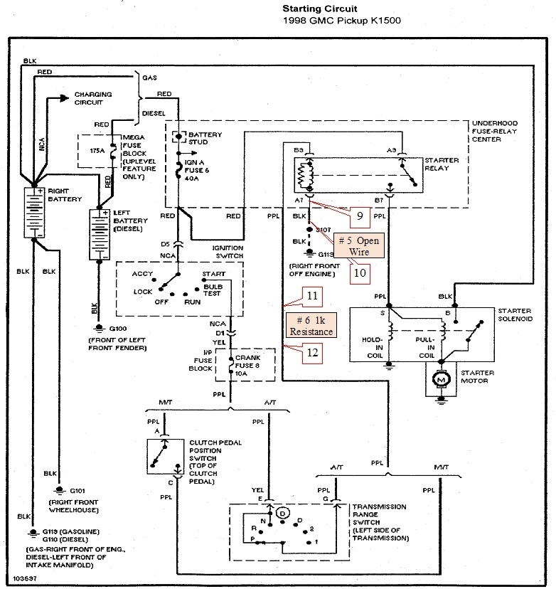
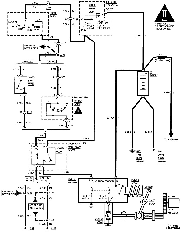
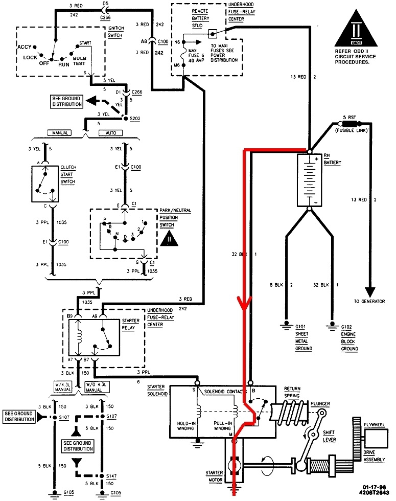
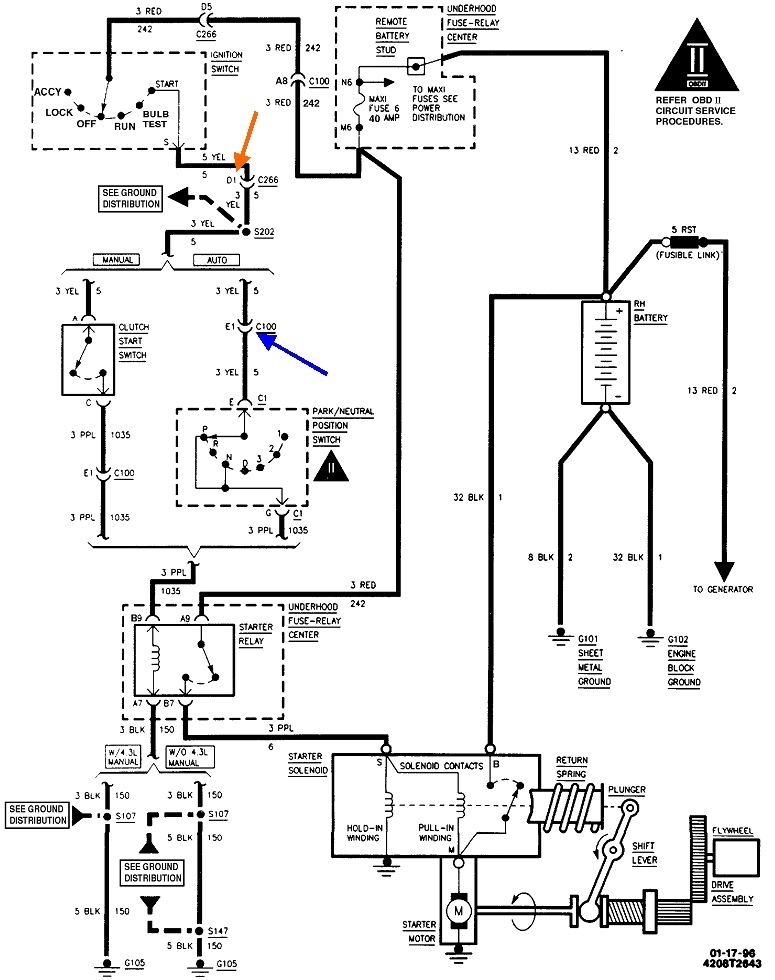
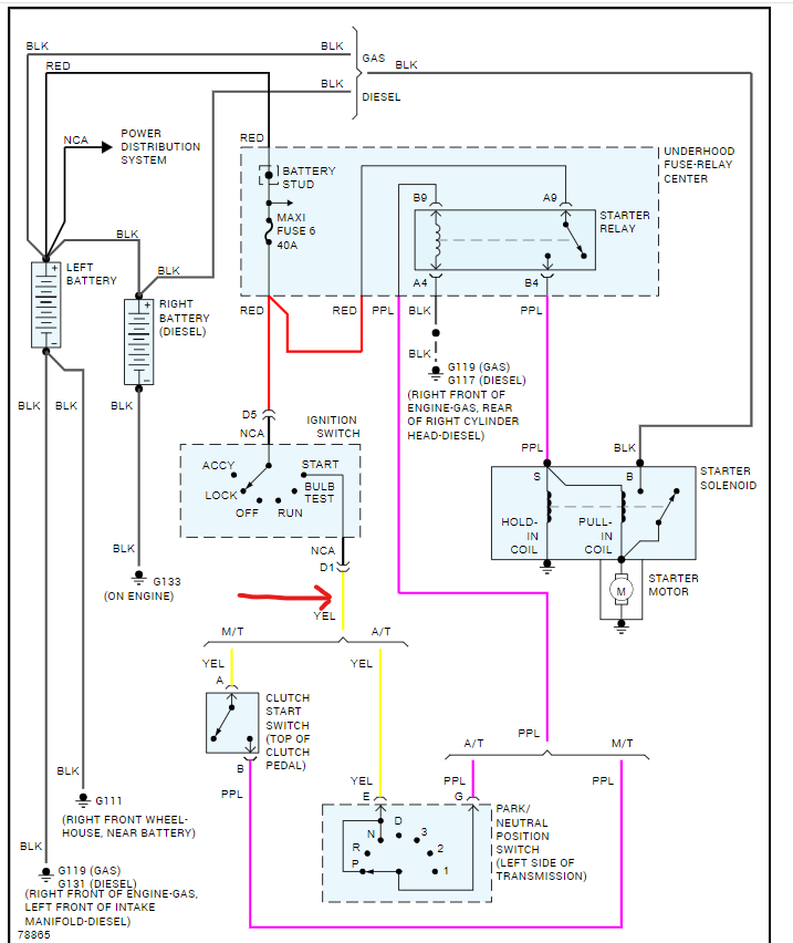
This first diagram is from my notes to myself for the two switches I put in the starter circuit of a '98 GMC that was donated to my program. It's drawn a little different, but it's basically the same as for your truck. Your diagram is in the second image.

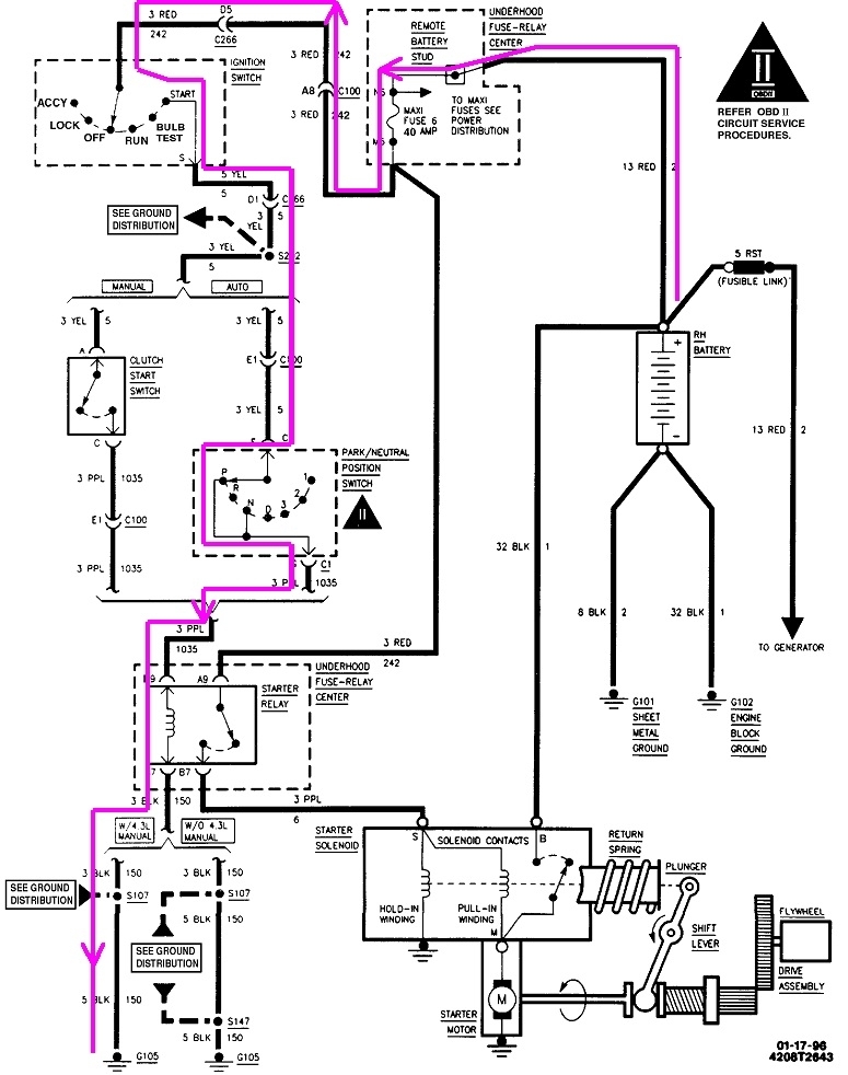
For reference, all starter circuits can be broken down into three parts; the low-current circuit, the medium-current circuit, and the high-current circuit. In the third diagram, I traced the low-current circuit in purple. Current will be very low, as in much less than one amp. Switch contacts can easily handle that, and the wires can be a small diameter. This is the circuit where you'll want to put the added-on switch.

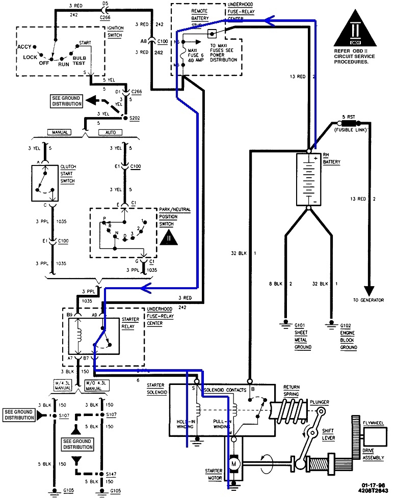
To complete the story, the ignition switch in "crank" sends current through the neutral safety switch, then the coil of the starter relay and turns it on. When that relay turns on, the medium current flows through the relay's contacts, then through two coils inside the starter solenoid on top of the starter motor. In the fourth diagram, that circuit is in blue. The electromagnetic fields are needed from both coils to build enough strength to pull the drive gear into engagement with the ring gear. Current through the "hold-in" coil goes to ground. Current through the "pull-in" coil continues on through the starter motor itself which has extremely low resistance, so it's like it's just a piece of wire. Total current flow through the two coils is around 10 to 15 amps. That's too much for the contacts in the ignition switch, but the relay can handle that.

Once the solenoid has engaged fully, a contact switches on the high-current circuit shown in the fifth diagram in red. This can be as high as 300 amps to get the starter motor spinning. Once it's up to speed, that will quickly drop to less than 200 amps. Due to that very high current, connections must be near perfect, but it's where we'll find most problems. It's also the least complicated part of the system. One note of interest here, once the solenoid switches on, battery voltage is applied to the starter motor right at the point where the pull-in coil is connected. That puts full battery voltage on both sides of that coil which bypasses it. Once the drive gear has engaged, it takes much less energy to hold it in place during cranking. By bypassing it, that few amps becomes available to go through the starter motor too. That little bit extra can be just what's needed on a real cold day to get an engine started.

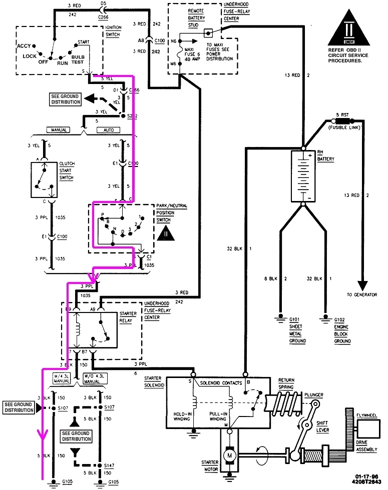
Finally, in the sixth diagram, I outlined the section where you can cut in and add a switch. That can't be done in the part between the battery and the ignition switch because that feeds everything else controlled by that switch, such as the heater fan, radio, wipers, and power windows. That section can have rather high current, in the area of five to ten amps. You'd need a pretty beefy switch there.

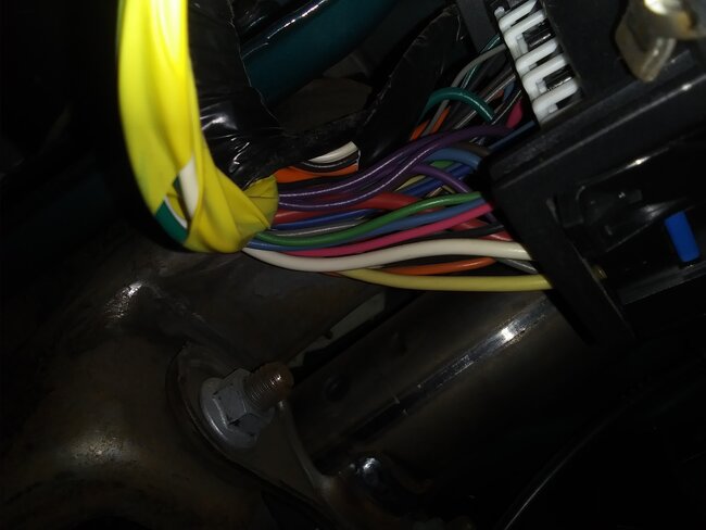
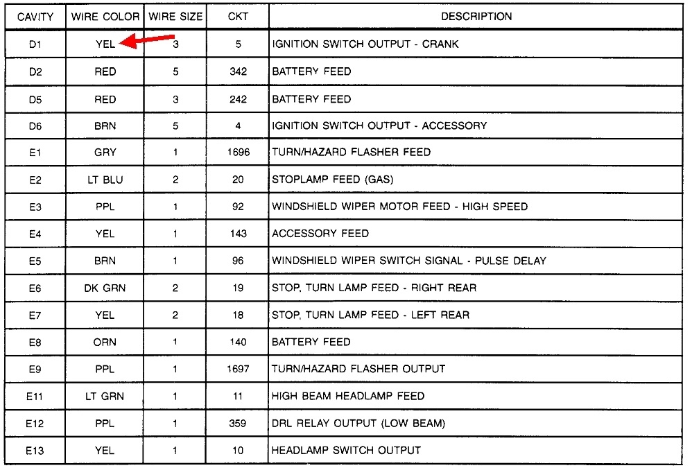
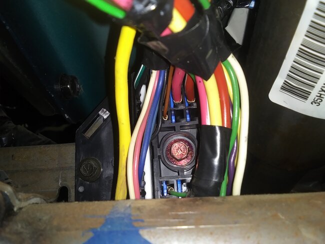
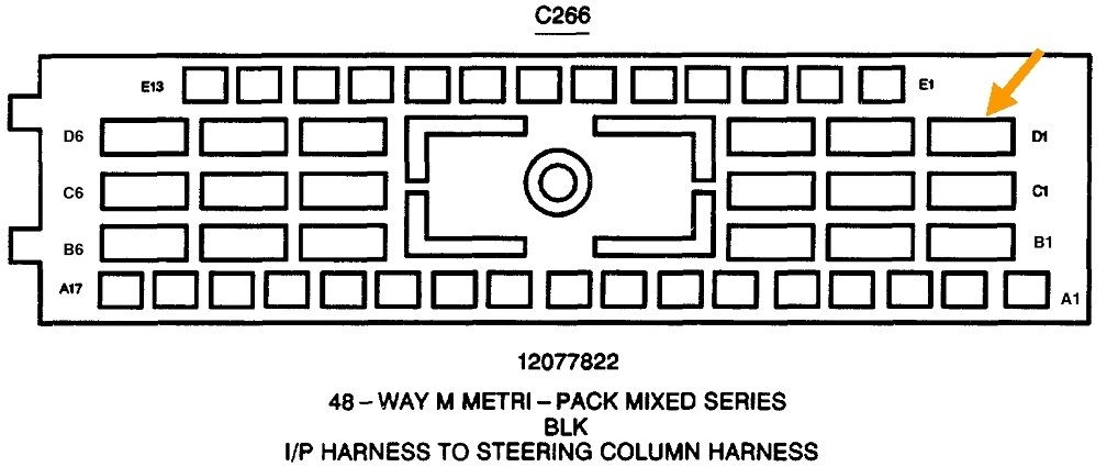
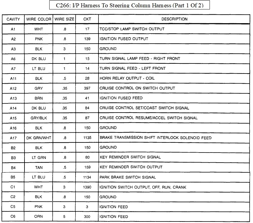
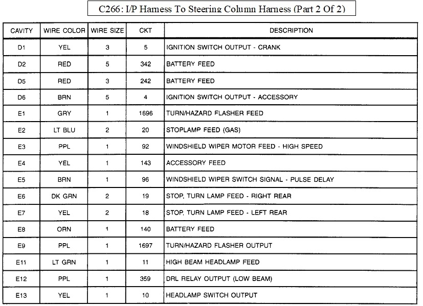
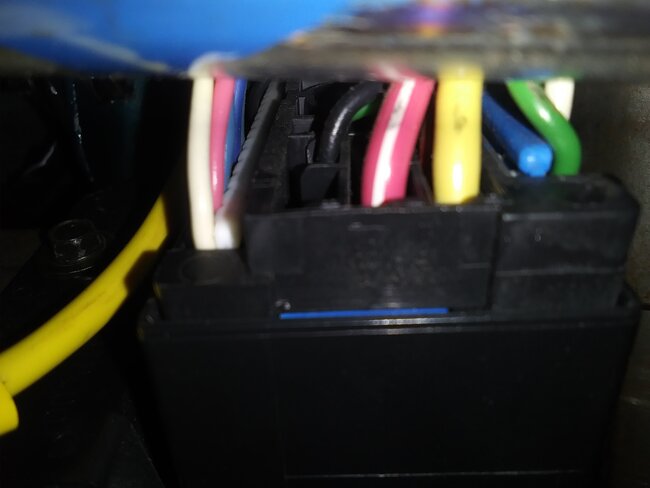
My preference would be to stay inside the cab. Look for connector C266 under or near the steering column. The diagram shows terminal "D1" as a yellow wire for this circuit. That's shown in the seventh drawing. If you plan on making this permanent, just cut that yellow wire on either side of the connector and extend them to the new switch. I like to be able to put things back the way they were, so the way I'd do this is to visit a pick-your-own-parts salvage yard, and pull out that wire with both of the mating terminals from the connector. On your truck, pull one of the terminals out of your connector and plug it into one of those you just harvested. Plug the other one into the connector. If you were able to get enough wire with each terminal, they might reach to the new switch, otherwise you'll just have to add some additional wire. Either solder the wires to the switch terminals, or you can use crimp-style universal terminals, but I always solder them too.

If you use a toggle switch, you'll have to remember to switch it to "No-Crank" mode every time you want it to do its thing. If you use a momentary push button, it's set automatically, but you'll have to press it every time you want to start the engine.

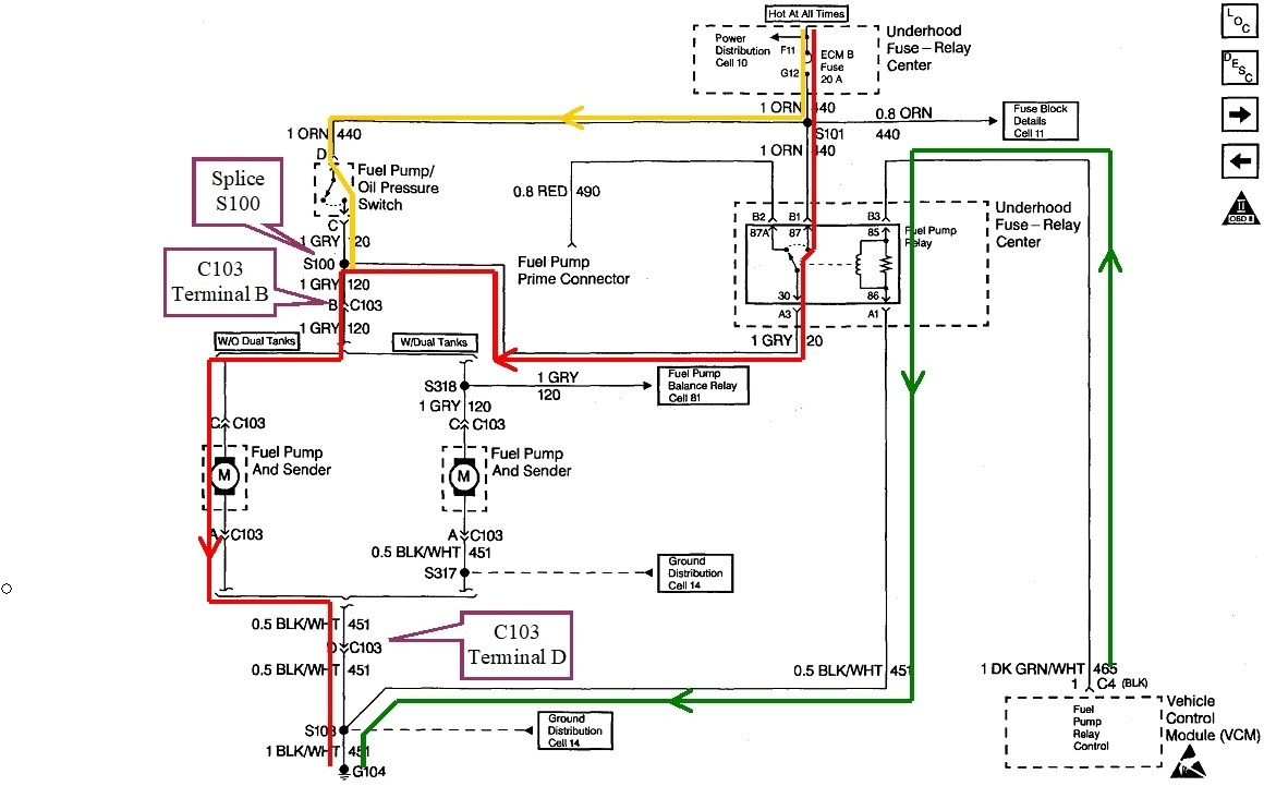
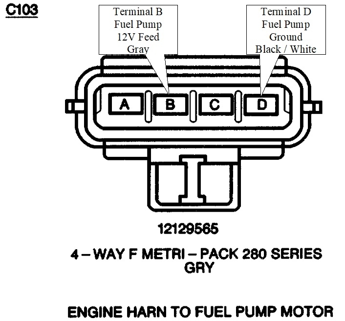
I'll work on the fuel pump circuit next, but that one will require going outside the cab, either under the hood or in back under the box.

By the way, if you need to make the diagrams bigger, copy and paste them into a typing program such as MS Word where they can be expanded. I can help with that if necessary.
Jan 18, 2024 at 6:01 PM
Avatar
BILL93240
  • MEMBER
  • 62 POSTS
I appreciate all the time and knowledge you have expressed but all I really need to know is which wire to cut to tap the switch into. Which wire running to the fuel pump under the chassis near the gas tank, and which wire in that bundle coming down the column from the steering wheel (the purple one maybe). I will try to crawl under the truck to look at the fuel pump wires today or tomorrow to look at the wires, weather permitting.
Jan 19, 2024 at 9:19 AM
Avatar
CARADIODOC
  • CERTIFIED EXPERT
  • 34,306 POSTS
Here's the condensed version for the starter cutout. Connector C100, (blue arrow), is the bulkhead connector on the firewall. Everything above that connector is inside, under the dash. Look for C266 near the steering column. The wire to cut is the yellow one in cavity D1. I pointed it out with the orange arrow in the second drawing. There will be multiple yellow wires for other circuits, so be sure you find the one in this location in the connector. It doesn't matter which side of the connector you cut that wire.

The fuel pump circuit is a little trickier. I'm gonna explain how it works so the rest of the description makes sense. You don't have to remember this later. The entire circuit is shown in the third diagram. The low-current circuit, shown in green, sends current through the fuel pump relay's coil, then to ground, to energize that relay. Normally this would be the ideal circuit to put the switch, but GM added a clinker, plus, this circuit is usually very short and hidden inside the under-hood fuse box. Best is to leave that alone, if possible. When the relay turns on, the higher current, shown in red, flows through the relay's contacts, the fuel pump motor, then to ground. This is exactly the same as how Chrysler and many other manufacturers do it. A cutout switch capable of handling ten amps or more would do nicely in this circuit, but it will require a lot of wire and a hole to run it inside the cab. The gray wire is buried within a large bundle, making it difficult to access anywhere except near the tank.

The problem with GM's circuit is they added a second feed circuit that I traced in yellow. With the engine off, fuel pressure should hold for days or weeks, but in case it bled down, all manufacturers run their fuel pumps for one second when you turn the ignition switch to "run". That's to be sure pressure is up for starting. After that, the relay gets turned on again when the Engine Computer sees engine rotation, (cranking or running). Once the engine is running, it will stall if the relay is removed.

With the yellow circuit that GM added, the fuel pump is also powered through a tap on the oil pressure switch. Here, if the fuel pump relay is removed, the pump will remain running as long as there's oil pressure, meaning the engine is running. If that relay fails or is left out on purpose, the symptom could be a long crank time because it can take a few seconds to build oil pressure while cranking, but the pump will run. To say that a different way, the cutout switch has to be after that part of the circuit so the 12 volts can't reach the pump from the relay or the oil pressure switch. Those two circuits join at splice S100. Where that splice is located is not shown, but most likely it's near the back of the engine. The best place to find the gray wire is back by the pump, terminal "B" in connector C103.

Alternatively, you could cut the pump's ground wire in terminal "D" in C103. That's down at the bottom of the diagram, a black / white wire, (black with a white stripe, or "tracer"). The connector is shown in the fourth drawing.

I looked at adding a cutout switch to the ignition system, but decided that is not a good idea. With Chryslers, there's a lot of places a switch can be added that will disable the fuel pump and ignition systems together, but on your truck, most of those two systems are separate, meaning they have little in common. If you disable only the ignition system to prevent theft, the injectors will still keep squirting fuel during repeated starting attempts. That fuel will wash the cylinder walls of their oil film, and dilute the engine oil. That often leads to spun bearings and an expensive engine repair or rebuild. Losing fuel doesn't cause any problems other than the no-start condition.
Jan 19, 2024 at 4:59 PM
Avatar
BILL93240
  • MEMBER
  • 62 POSTS
I'm sorry, the long-winded technical explanations and schematic diagrams are just confusing me. Could we keep it to what wire to cut and tap into? I checked under the truck and there is a wire harness with 8 wires running back to the fuel pump and taillights. Could you tell me which one of those wires to cut to shut off the fuel pump? I could run the bypass wires into the back of the cab and install a switch somewhere in there. Regarding the starter you said to cut the yellow wire, but I read on forums to cut the purple wire. And, if I disable the starter and the engine isn't cranking, how will fuel enter the cylinders to contaminate the oil?
Jan 21, 2024 at 6:30 PM
Avatar
CARADIODOC
  • CERTIFIED EXPERT
  • 34,306 POSTS
Other people can view this conversation if they're researching a similar issue, so we have to include enough detail to help as many people as possible. Without the detailed explanation related to the fuel pump circuits, a person may not get the results they're expecting. I got very specific as to which color wires to look for and where to look for them. I even copied and formatted for uploading the connector views so there would be no confusion as to which wire to cut. You don't have to know or remember the circuit explanations I included. You still haven't told me what type of switch you want to use, so I'm imagining the most common switch a person might choose, then going from there.


If you want to disable the starter system, cut the yellow wire in the 48-pin connector under the steering column, cavity "D1".

To disable the fuel pump, cut the gray wire or the black / white wire at the connector for the fuel pump. This will likely require dropping the tank.


There are a lot of other ways to disable these circuits. Some require running a lot of wire. Some require a lot of explanation to find the right wires. Unfortunately, when you tell me there's a bundle of eight wires, they don't show that on the diagrams, so I have no way of knowing what each of those wires is for. If you find a gray wire in there, you can take your chances and cut it to see if that disables the fuel pump. There are many wires of the same color, but I'm pretty confident there are no tail light wires running up by the fuel pump connector. That's why I feel safe sending you right to that connector. There are only four wires going to the fuel pump, two for the pump motor and two for the fuel level sending unit. If you can follow that bundle of four wires to the harness you found with eight wires, I'd be a lot more confident you can cut the gray wire, if there's one in there.

Let me know if one of those works for you.

Jan 22, 2024 at 5:42 PM
Avatar
BILL93240
  • MEMBER
  • 62 POSTS
Hello, a while back I asked about installing a cutoff switch for theft prevention. After consideration I concluded the best solution for me would be to tap into one of the wires descending from the steering wheel column under the dash and install a toggle switch to defeat any attempt by a thief to steal the vehicle. I took a picture of the wire harness and would like to know what wire to cut to patch the toggle switch into. Just need to know which wire, probably the one that actuates the starter. When defeated it will mimic a dead battery, or at least one that is too weak to turn over the engine. I will locate the switch in a hidden spot. The picture was taken from under the dash on the left of the steering column.
Apr 13, 2024 at 4:19 PM (Merged)
Avatar
CARADIODOC
  • CERTIFIED EXPERT
  • 34,306 POSTS
This diagram is for your starter circuit. I added arrows to show the best wires to cut. You should find the yellow wire in that harness, but to be sure there aren't two or more yellow wires, it might be smart to use a test light at a connector terminal to be sure it's the right one. You should find 12 volts on it only when the ignition switch is in the "crank" position.

Outside the cab, the neutral safety switch and the starter relay are in the circuit. That relay draws very little current so you won't need much of a switch. It can even be a momentary push button switch that you have to press and hold while turning the ignition switch. If you use a toggle switch, you only have to switch it off when you want it to do its thing.
Apr 13, 2024 at 4:19 PM (Merged)
Avatar
BILL93240
  • MEMBER
  • 62 POSTS
It looks like there is only one yellow wire in that wire bundle in my photo (the one at the bottom). Would that be the one? I also read on a forum that a purple wire in that wire bundle would do, what do those purple wires connect to? And what amperage toggle switch should I purchase?
Apr 13, 2024 at 4:20 PM (Merged)
Avatar
CARADIODOC
  • CERTIFIED EXPERT
  • 34,306 POSTS
The yellow wire goes from the ignition switch through the bulkhead connector, then down to the neutral safety switch. The purple wire continues the current path from the neutral safety switch, up to the coil of the starter relay. Adding a switch to the purple wire would do the job, but you'd have to run the wires through the firewall to your switch. Common sense says use the yellow wire instead. It's already right there under the dash.

Starter circuits can be broken down into three individual circuits. The low-current circuit includes the ignition switch, neutral safety switch, and the coil for the starter relay. The contacts in the starter relay switch on the medium-current circuit that sends current to the starter solenoid on top of the starter motor. The solenoid switches on the high-current circuit that runs the starter motor. The typical relay coil will draw much less than a single glove box bulb, perhaps one or two tenths of an amp. The smallest of toggle switches can easily handle that. They're typically good for at least three amps, and most can handle six to ten amps.
Apr 13, 2024 at 4:20 PM (Merged)
Avatar
BILL93240
  • MEMBER
  • 62 POSTS
I guess I could snip the yellow wire and try the key, and if it doesn't turn over I would have it right? And if not I could always use a butt connector to patch the wire back up. OTOH there looks like three purple wires in that bundle, would any one of them do? Sorry I am not very technical with schematics and electronics but I am a decent DIYer.
Apr 13, 2024 at 4:20 PM (Merged)
Avatar
CARADIODOC
  • CERTIFIED EXPERT
  • 34,306 POSTS
Nope. Stay away from any purple wires under the dash. This is one area where GM has standardized wire colors. They've used a purple wire from the neutral safety switch to the starter relay for decades, but that wire runs from the transmission to the under-hood relay / fuse box. It is not inside the cab. Only the yellow wire from the ignition switch is under the dash.

You should see connector C266 near the base of the steering column. It looks like the first drawing. My orange arrow is pointing to terminal D1. That should be the yellow wire to cut. You can cut it on either side of the connector.
Apr 13, 2024 at 4:20 PM (Merged)
Avatar
BILL93240
  • MEMBER
  • 62 POSTS
So just to be sure, cut the bottom (yellow) wire in the wire cluster in my picture I submitted with my original post? Sorry, don't mean to be repetitive, just trying to keep it simple.
Apr 13, 2024 at 4:20 PM (Merged)
Avatar
CARADIODOC
  • CERTIFIED EXPERT
  • 34,306 POSTS
I can't tell what the connector looks like, but I do see a lot of wires, and a yellow one at the end, like in the drawing.
Apr 13, 2024 at 4:20 PM (Merged)
Avatar
BILL93240
  • MEMBER
  • 62 POSTS
That wire bundle comes down the steering shaft from the steering wheel. Likely the horn and blinkers and wipers in those wires. So one of those wires would come from the keyed ignition switch on the column. You think it would be that yellow one?
Apr 13, 2024 at 4:20 PM (Merged)
Avatar
CARADIODOC
  • CERTIFIED EXPERT
  • 34,306 POSTS
If you still don't believe me, poke a test light into that connector by back-probing right next to the terminal. You'll see it light up when you turn the ignition switch to "crank".
Apr 13, 2024 at 4:20 PM (Merged)
Avatar
BILL93240
  • MEMBER
  • 62 POSTS
No, I believe you, it's just that I am a carpenter and not an electrical expert. I don't see any terminal and I don't possess a test light. All I see is a bundle of wires coming down the steering column and would like to know which one to cut and would want to be sure and not make any mistake. So it is that yellow wire in my photo, yes or no.
Apr 13, 2024 at 4:20 PM (Merged)
Avatar
CARADIODOC
  • CERTIFIED EXPERT
  • 34,306 POSTS
Look back at the drawing I just posted with my orange arrow pointing to terminal "D1". Right under it are "A1", "B1", and "C1". Now look at the next drawing that shows the first half of the list of wires. "A1" is listed as "white". "B1" is not listed, so it's empty, but "B2" is right next to it and is black. "C1" is listed as another white wire. "A1" is shown as a much smaller terminal than those other three. If that's what you see in your connector and they're right by the yellow wire, that yellow one is the one to cut.

This is just like reading a blueprint, except instead of reading dimensions, we're reading shapes and locations.
Apr 13, 2024 at 4:20 PM (Merged)
Avatar
BILL93240
  • MEMBER
  • 62 POSTS
Hello there, I got sidetracked a bit and am now back on this project. I removed the plastic lower dash panel to expose what I think is the c266 connector, right? It looks like there are two purple wires going into that connector, to the left a light purple wire between a white and a blue wire, and to the left a darker purple wire between a green and a white wire. Sorry that metal tube is blocking the lower part of the connector. Which purple wire would be the one to cut to disable the starter? This would be a good spot to do the wire splice as it would be concealed by the plastic panel and not exposed under the dash.
May 24, 2024 at 11:08 AM
Avatar
BILL93240
  • MEMBER
  • 62 POSTS
Sorry I took so long, still learning, but I think I am understanding this wiring a little more now.
May 24, 2024 at 11:09 AM
Avatar
BILL93240
  • MEMBER
  • 62 POSTS
Seems the yellow wire between the pink and the red wires goes down to the D1 in the block. It's thicker so more amps? Which one (and why) would be better to cut, the purple or the yellow wire? I will try to get a pic of the lower block with the D1 connection at the bottom.
May 24, 2024 at 6:44 PM
Avatar
BILL93240
  • MEMBER
  • 62 POSTS
I brought this up in another post, I am trying to install a kill switch that defeats activation of the starter when the key is turned. The picture shows the C266 connector that accepts wires from the steering column and is located below the column behind a plastic lower dash panel. I understand cutting one of the purple wires or yellow wires, and patching in a toggle switch, will do the trick. My question is which one. The fat yellow wire to the left in the picture goes to the airbag I believe, so eliminate that one. So that leaves a light purple wire to the left of the bolt, and a dark purple wire, a fat yellow wire, and a thinner yellow wire to the right of the bolt. I would like to know the best wire to cut for the most reliable defeat of the starter, and why. And the smallest wire possible with the smallest amperage so I can use thinner patch wires. If you could explain the purpose of each wire I would appreciate that. I think I can figure out the hidden location of the switch on my own but any suggestions would be appreciated. Thanks for taking my question, regards, Bill.
May 26, 2024 at 9:31 AM (Merged)
Avatar
STRAILER
  • CERTIFIED EXPERT
  • 53,854 POSTS
The yellow wire in the D1 slot of the ignition switch connector is the one you want to use, please check the wiring diagrams below to see what I am talking about. Check out the images (below). Please let us know what happens.
May 26, 2024 at 9:34 AM
Avatar
BILL93240
  • MEMBER
  • 62 POSTS
Thanks for taking my question, Ken. Would that be the fatter or thinner yellow wire on the right (in my photo)? Also, what about that dark purple wire right of the bolt, what does that do, I read elsewhere that people use it also? My patch wire I have handy is kind of small gauge so the thinnest wire possible would be best. If you don't mind, could you explain the purpose of the yellow and purple wires? And would wire nuts or butt connectors be ok to use on the wires (I will try to soldier them if I can get my soldiering gun up in there). Sorry if I sound picky but I want to do the best job possible.
May 26, 2024 at 2:07 PM
Avatar
CARADIODOC
  • CERTIFIED EXPERT
  • 34,306 POSTS
I'm back. Please forgive me for the long delay. I had computer trouble for a couple of weeks. Also, I asked Ken to post a reply for me, but I neglected to notice I never posted the list of wires I wanted him to refer you back to. I have them below now.

As near as I can tell, the purple wire you're looking at is in spot C5. If I have that right, it's one of the ignition 12-volt feed wires to the ignition switch, but it isn't related to the starting system. That is likely for things like the heater fan or wipers.

Stick with the yellow wire in terminal D1. That one will have very low current flow, so any wire you have will be fine, and the current flow is only there during cranking. If you use an ignition feed wire instead, you'll need a switch and wire size that can handle much higher current all the time. It's more likely for a switch in that application to fail while driving. That would leave you sitting on the side of the road.

As for connections, the only acceptable method is to solder the splices, then seal them with heat-shrink tubing. Wire nuts do not belong anywhere there's moisture or vibration. Butt connectors do not seal out moisture or salt. The best heat-shrink tubing has hot-melt glue inside to do a much better job of sealing out moisture, but it really isn't necessary under the dash.
May 29, 2024 at 6:00 PM
Avatar
BILL93240
  • MEMBER
  • 62 POSTS
No need to apologize, you and the other mechanics have been so helpful with my questions and have saved me $$ on repairs and hopefully helped keep my truck from being stolen. In my photo it looks like two yellow wires, a fat one and thin one, so I will trace them down to the D1 terminal in the block to determine which one to cut. I will get back to you shortly to let you know how it works. Best regards, Bill.
May 29, 2024 at 8:26 PM
Avatar
BILL93240
  • MEMBER
  • 62 POSTS
I took a picture of the bottom end of the block and compared the wire colors to the chart and some of the wire colors don't match. But would you still determine it would be the yellow wire (the one next just to the right of the pink and white striped wire.
May 30, 2024 at 3:06 PM
Avatar
CARADIODOC
  • CERTIFIED EXPERT
  • 34,306 POSTS
To be sure you have the right wire, poke a test light into the terminal, either side of the connector, then watch what it does. If you have the correct yellow wire, the test light will be off at first, and light up full brightness when you turn the ignition switch to "crank". The test light must not be on when the ignition switch is in any other position.
May 30, 2024 at 8:53 PM
Avatar
BILL93240
  • MEMBER
  • 62 POSTS
Good idea, I will try to get my hands on a test light, or fashion one out of a 12 volt bulb and a couple of wires. Will let you know the results, probably this weekend.
May 31, 2024 at 11:04 AM
Avatar
BILL93240
  • MEMBER
  • 62 POSTS
Finally got er done. The yellow wire is a pretty large gauge so I used lampcord to connect the switch. I want to thank you for the time you took to give me the info to track down the best connection among all these wires, it works as I intended it. I am very meticulous in what I do and try for the best result every time, and I am satisfied I have achieved it. Till the next problem, cheers and happy trails, Bill.
Jun 2, 2024 at 8:01 AM
Avatar
STRAILER
  • CERTIFIED EXPERT
  • 53,854 POSTS

CARADIODOC is one of our best, thanks for letting us know. Please use 2CarPros anytime we are here to help.
Jun 2, 2024 at 9:50 AM
Avatar
CARADIODOC
  • CERTIFIED EXPERT
  • 34,306 POSTS
Dandy. I had a reputation at the dealership of being the slowest mechanic in the shop, but I rarely had a comeback or complaint. My managers appreciated that, and I have an appreciation for people like you who do a tidy, careful job. It beats apologizing to your friends for doing sloppy work. Happy to hear you got this handled.
Jun 2, 2024 at 1:03 PM
Avatar
BILL93240
  • MEMBER
  • 62 POSTS
Yep, and in the process I learned a lot about auto electric and wiring schematics. Like you, my house framing jobs took extra time but they were never knocked down by the inspector. Better and cheaper to do it right once.
Jun 2, 2024 at 1:30 PM
Avatar
CARADIODOC
  • CERTIFIED EXPERT
  • 34,306 POSTS
Interesting. I enjoy framing too, and building stairs. My friend put up my shop many years ago, and nothing was straight or plumb. Now I'm fixin' to rebuild my house after a house fire, but I don't want my friend involved. His only bragging right is he's fast. Well, I don't want fast. I want straight and level.

The good news is we have a real lot of people in my area who want to work. Those who do quality work are always in demand and hard to hire. To my knowledge, there are no construction companies here with bad reputations. Too bad that's not the case all over the country.
Jun 2, 2024 at 1:42 PM
Avatar
BILL93240
  • MEMBER
  • 62 POSTS
Exactly, I turned down more jobs than I actually took.
Jun 2, 2024 at 1:48 PM