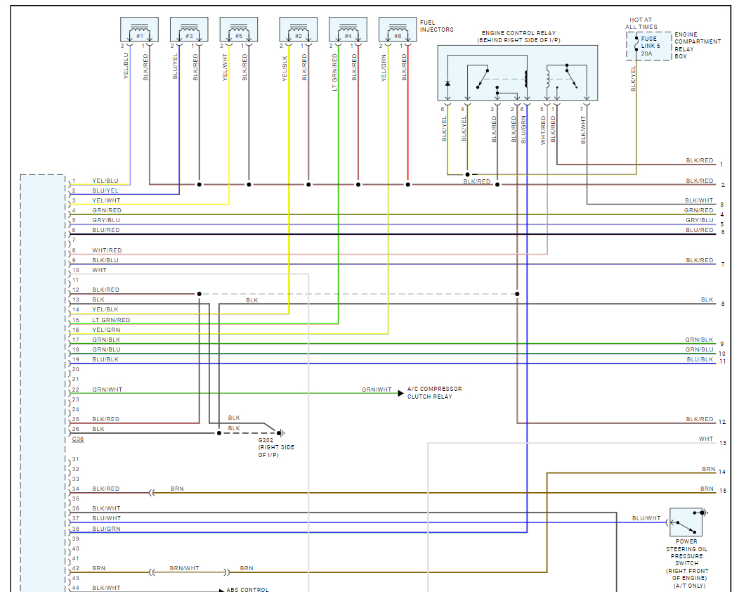
I have a V6 6G74 challenger, I came to find out that the wiring for the coils and injectors were tempered, the engine misfires and the engine goes off after running for a while.
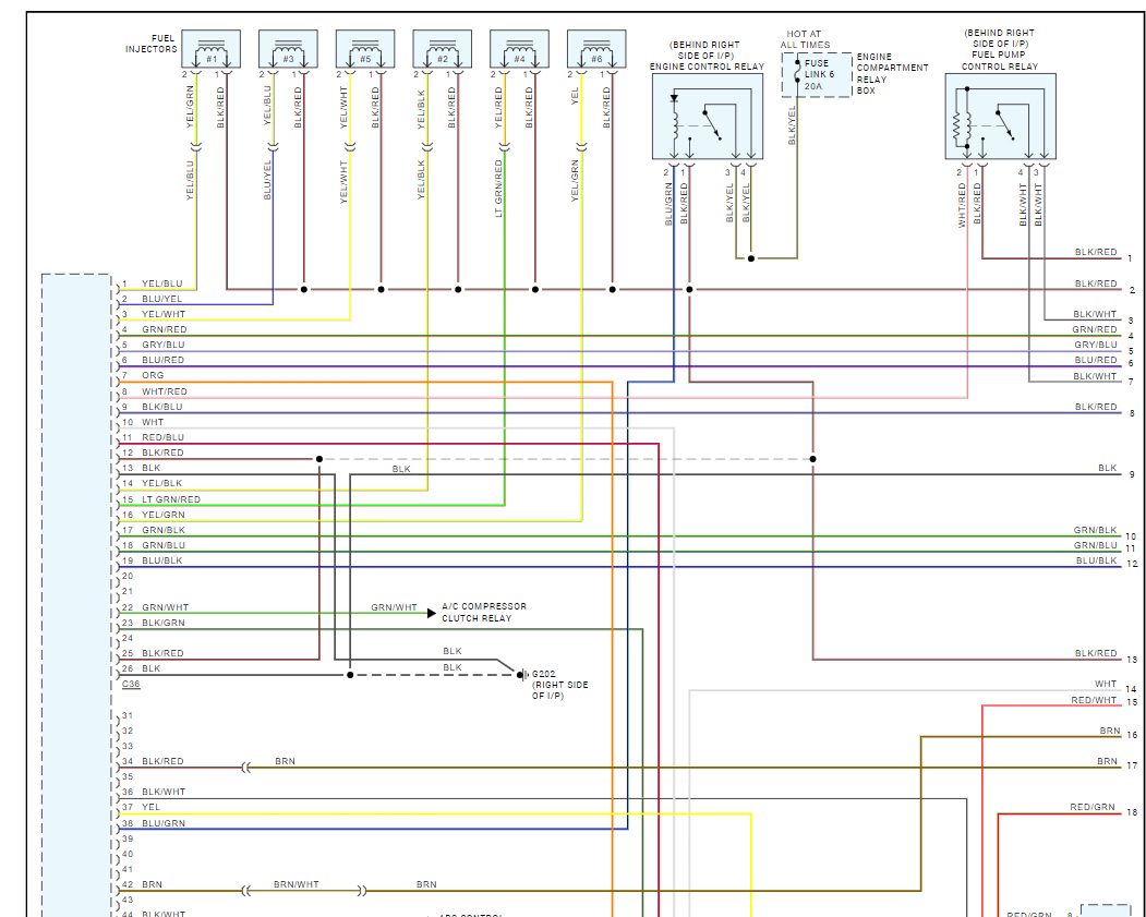
The power + for coils on the right bank is tapped from a bla/ whi wire on the injector drive.
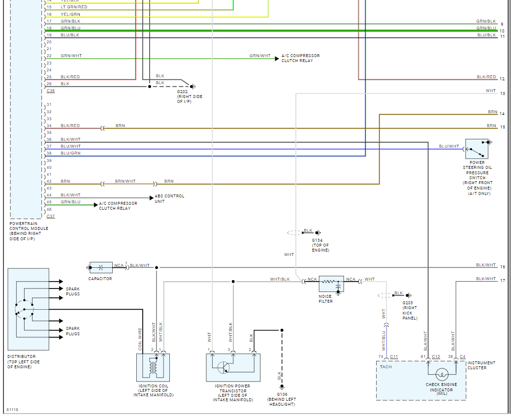
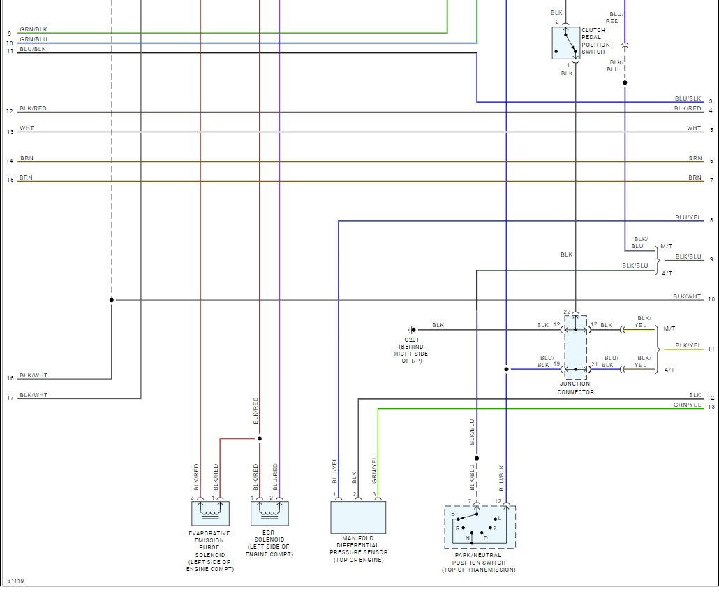
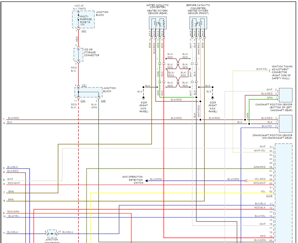
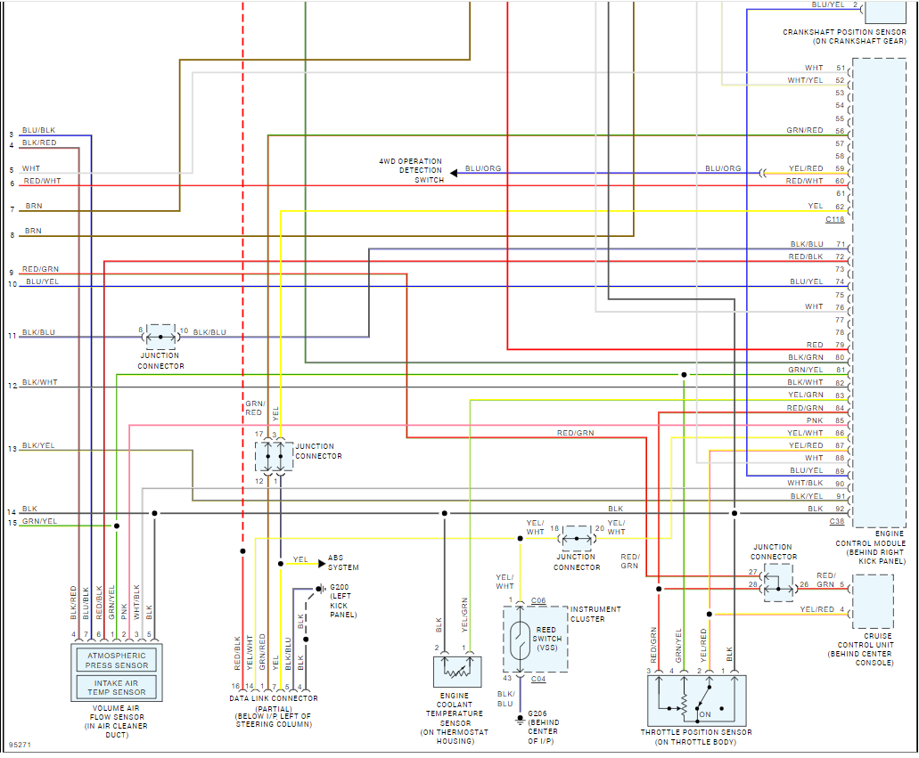
Signal wire for cylinder #6 is connected with a Red/Gre wire going to the Map sensor and it had no spark, therefore he tapped the signal from cyl #1 to supply cyl #6 and it has spark.
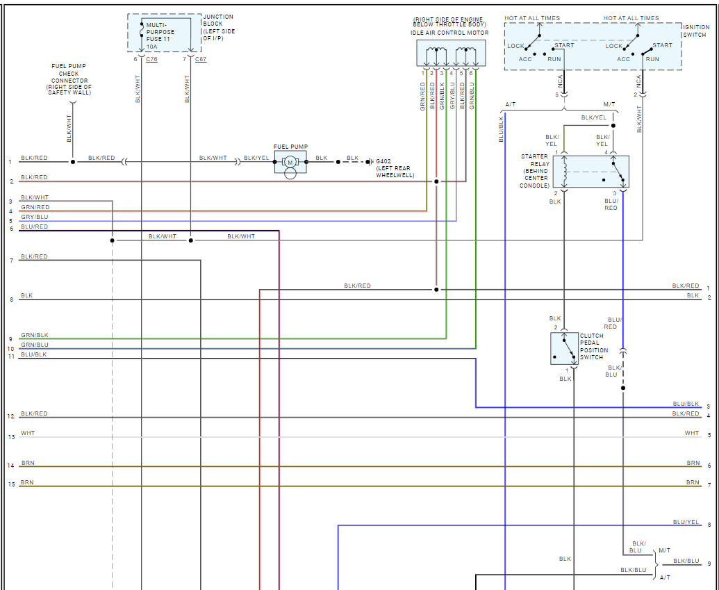
In addition to that when one of the pickup sensor is disconnected the air con fan and the fuel pump runs and go off in seconds.
My questions are
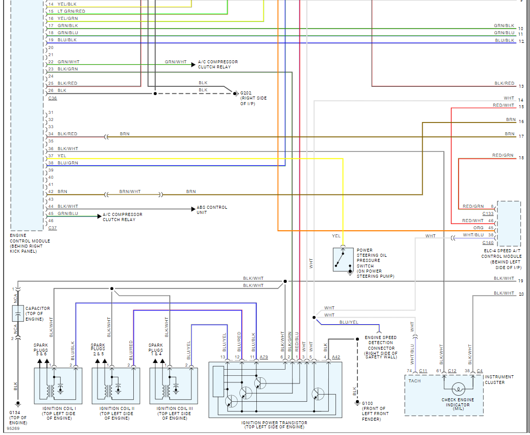
1 Can one signal wire control two coils at different times
2 what controls the firing of the coils
3 why does the air con fan and the fuel pump runs when the pickup sensor is disconnected.
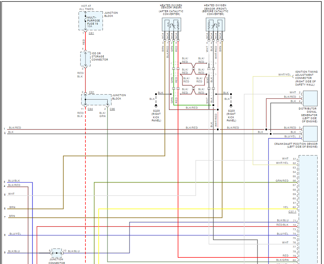
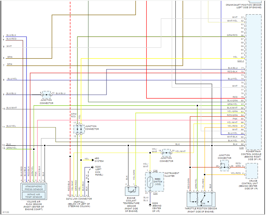
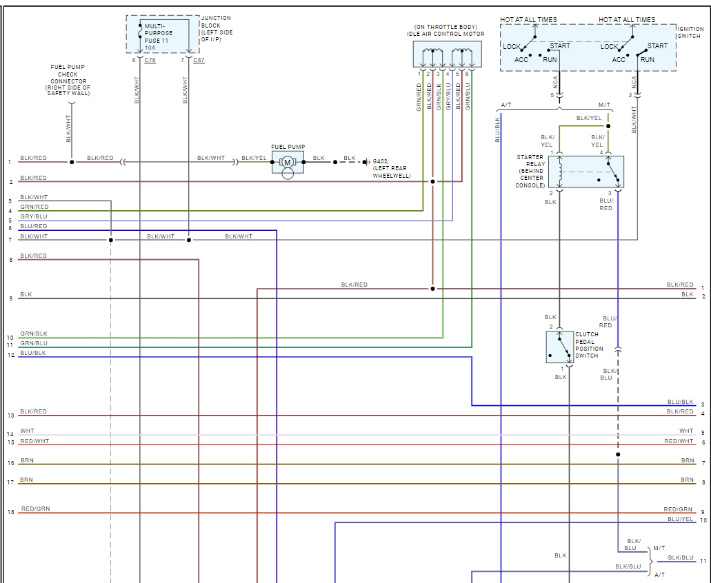
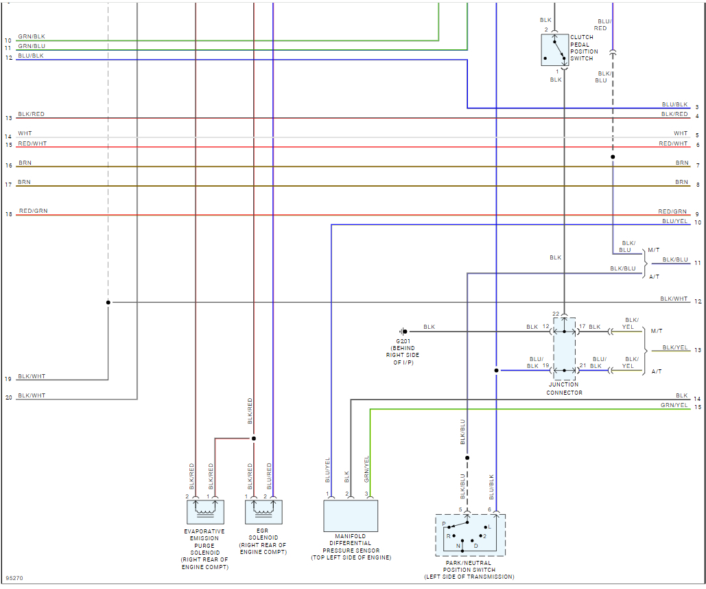
Kindly help me with a wiring diagram to get things back to normal.
Thank you
The power + for coils on the right bank is tapped from a bla/ whi wire on the injector drive.
Signal wire for cylinder #6 is connected with a Red/Gre wire going to the Map sensor and it had no spark, therefore he tapped the signal from cyl #1 to supply cyl #6 and it has spark.
In addition to that when one of the pickup sensor is disconnected the air con fan and the fuel pump runs and go off in seconds.
My questions are
1 Can one signal wire control two coils at different times
2 what controls the firing of the coils
3 why does the air con fan and the fuel pump runs when the pickup sensor is disconnected.
Kindly help me with a wiring diagram to get things back to normal.
Thank you
Jun 5, 2024 at 12:35 PM