Hi,
If the pressure plate is stuck on the release bearing, do you have enough access to unbolt the pressure place? If you unbolt it from the flywheel, the pressure plate should come out with the trans.
____________________________________________
Here are the removal and replacement procedures for this vehicle. Take a look through them and see if it helps. The attached pics correlate with the directions.
____________________________________________
2007 Hyundai Tiburon V6-2.7L
Removal and Installation
Vehicle Transmission and Drivetrain Manual Transmission/Transaxle Service and Repair Procedures Removal and Installation
REMOVAL AND INSTALLATION
REMOVAL
CAUTION
^ Use fender covers to avoid damaging painted surfaces.
^ To avoid damage, unplug the wiring connectors carefully while holding the connector portion.
NOTE
^ Mark all wiring and hoses to avoid misconnection.
^ Inspection the timing belt before removing the cylinder head.
^ Turn the crankshaft pulley so that the No. 1 piston is at top dead center.
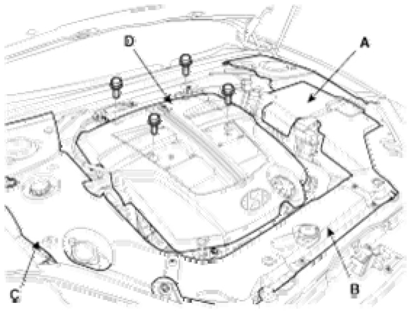
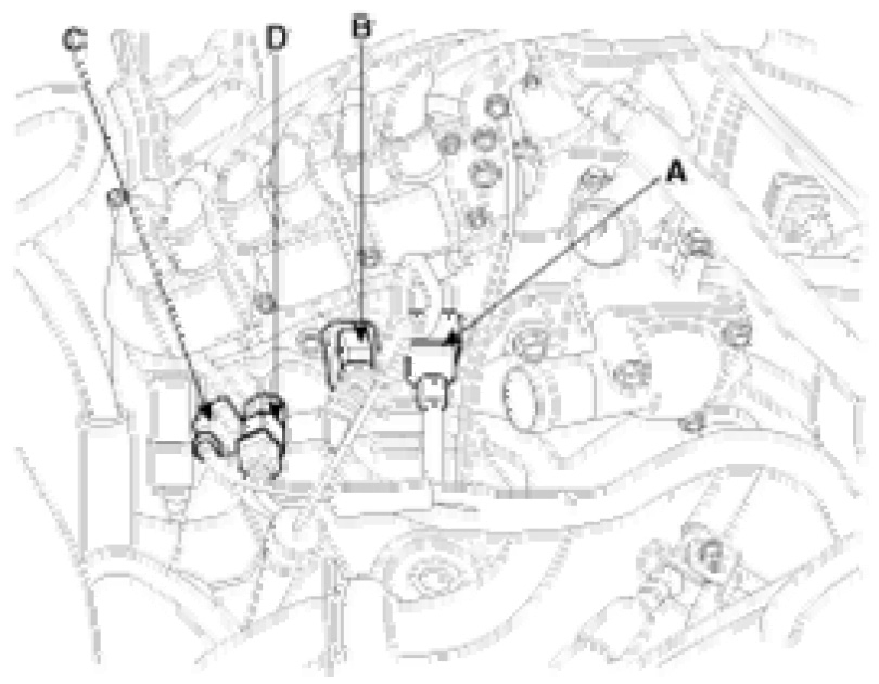
1. Remove the side cover (D) and the engine cover (A, B, C).
pic 1
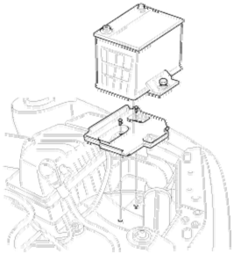
2. Disconnect the battery terminal and the battery.
pic 2
3. Remove the radiator cap to speed draining.
4. Remove the radiator drain plug and drain engine coolant.
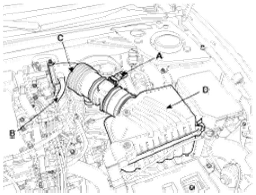
5. Remove the air cleaner assembly.
(1)Disconnect the air flow sensor (AFS) connector (A).
(2)Remove the breather hose (B) from intake hose (C).
(3)Remove the intake hose (C) and air cleaner upper cover (D).
(4)Remove the air cleaner lower cover (A).
pic 3
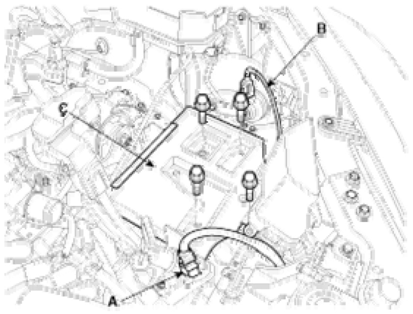
6. Disconnect the front connector (A) and horn conenctor (B).
7. Remove the battery try (C).
pic 4
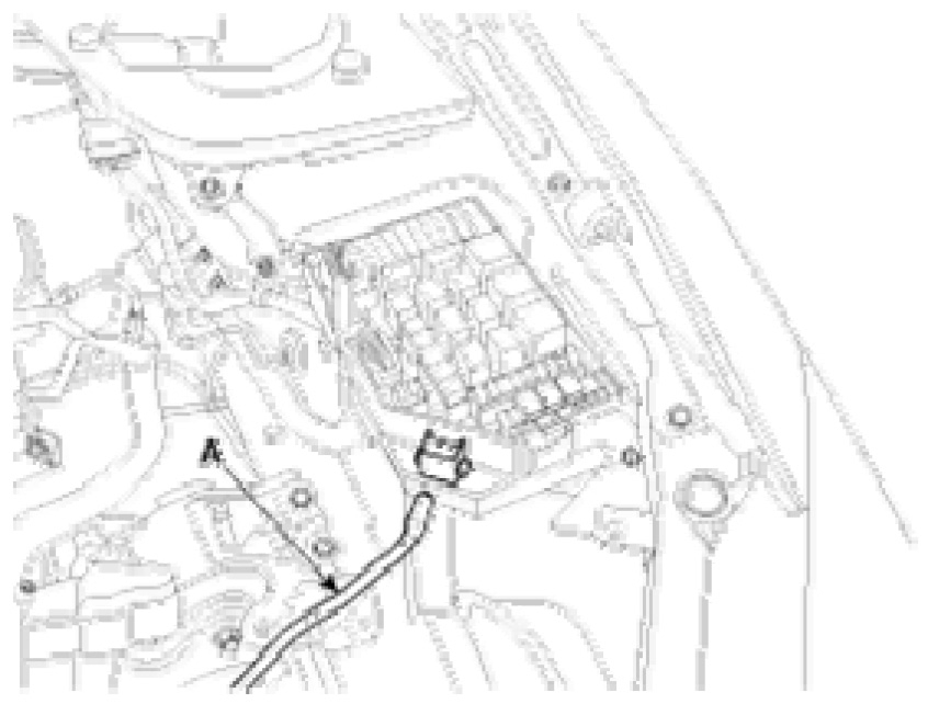
8. Remove the fuse box cover.
9. Disconnect the terminals (A) from the fuse box.
pic 5
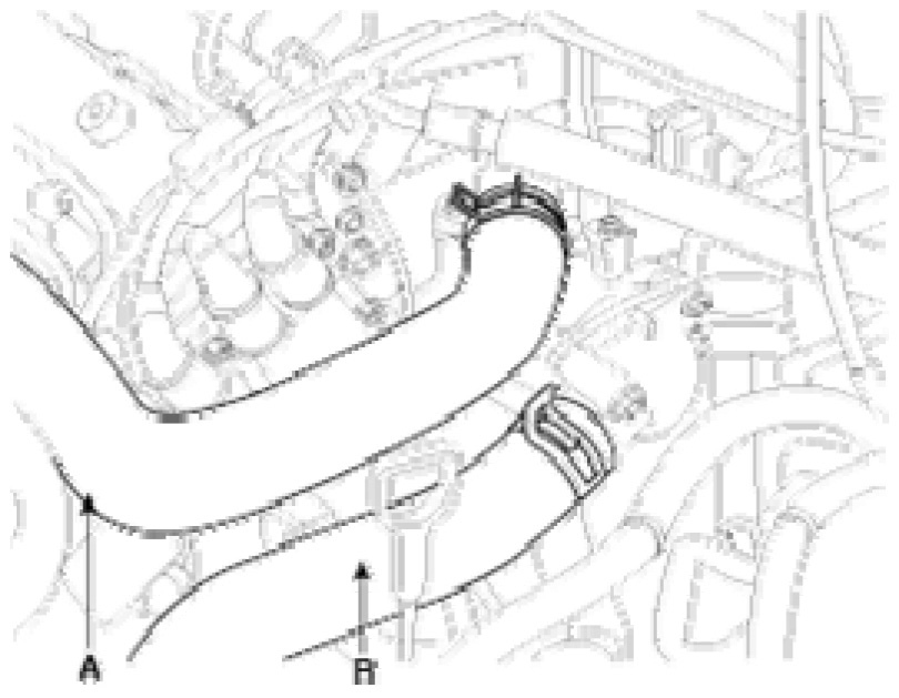
10. Remove the upper radiator hose (A) and lower radiator hose (B).
pic 6
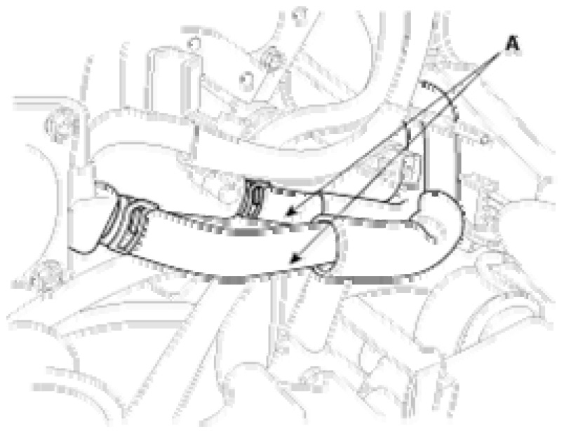
11. Remove the heater hoses (A).
pic 7
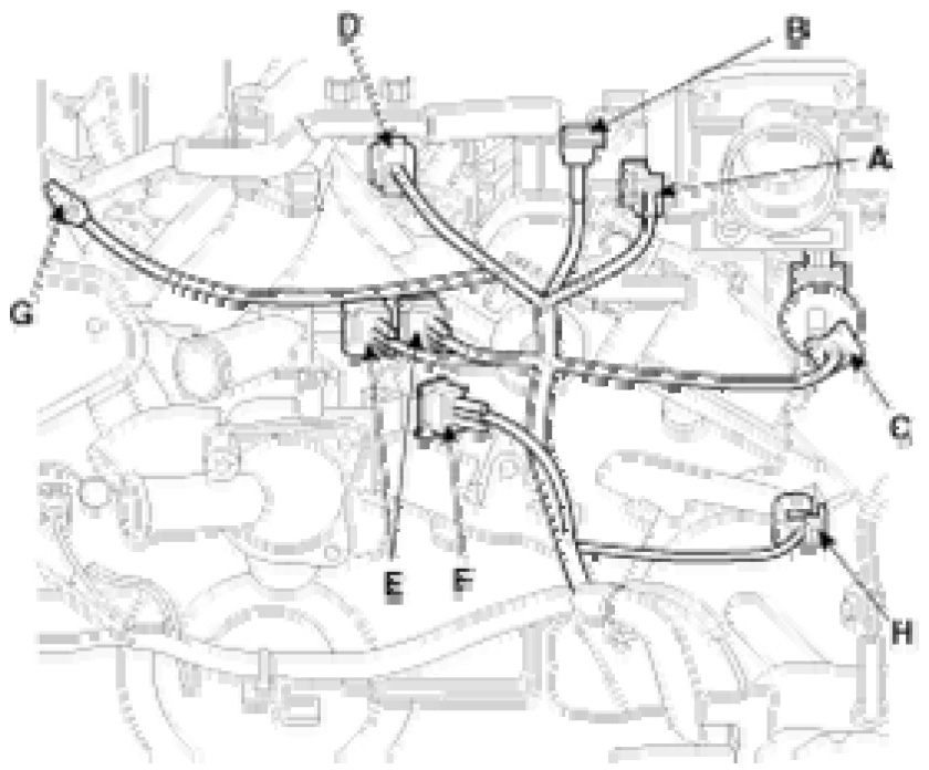
12. Remove the engine wire harness connectors and wire harness clamps from the cylinder head and the intake manifold.
(1)Throttle position sensor (TPS) connector (A).
(2)Idle speed actuator (ISA) connector (B).
(3)Purge control solenoid valve (PCSV) connector (C).
(4)Injector connector (E).
(5)Knock sensor connector (F).
(6)Camshaft position sensor (CPS) connector (G).
(7)Engine ground line (F).
(8)Heated oxygen sensor (Bank 2, Sensor 1) connector (H).
pic 8
(9)Engine temperature coolant sensor connector (A).
(10)Ignition coil connector (B).
(11)Crankshaft position sensor connector (C).
(12)Heated oxygen sensor (Bank 1, Sensor 2) connector (D).
pic 9
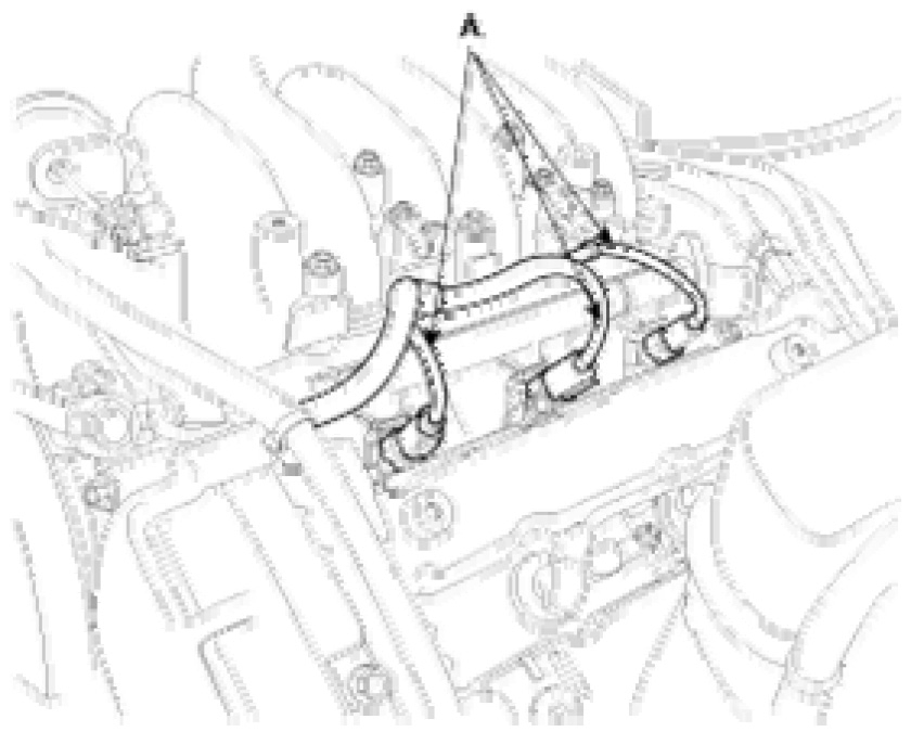
(13)Three fuel injector connectors (A).
pic 10
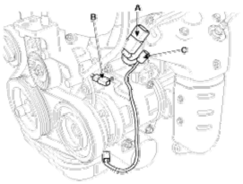
13. Disconnect heated oxygen sensor (bank 1, sensor 1) connector (A), air compressor switch connector (B) and oil pressure sensor connector (C).
pic 11
14. Remove the fuel inlet from delivery pipe (A).
pic 12
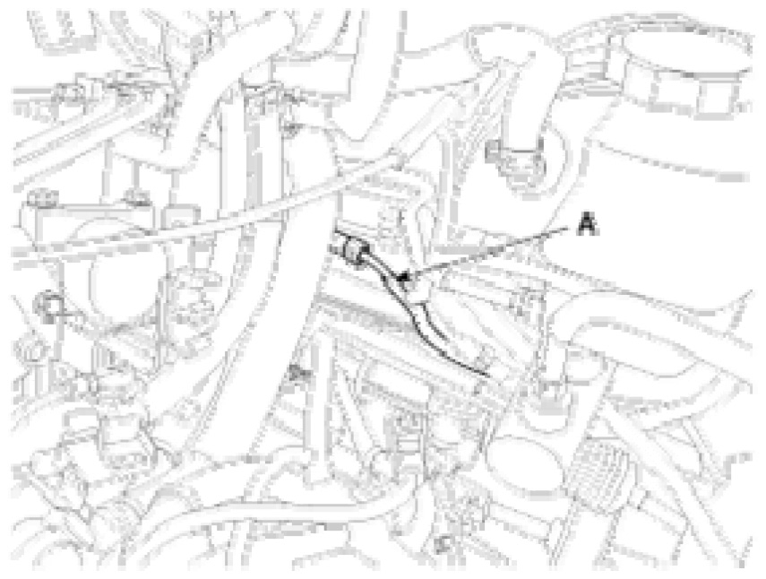
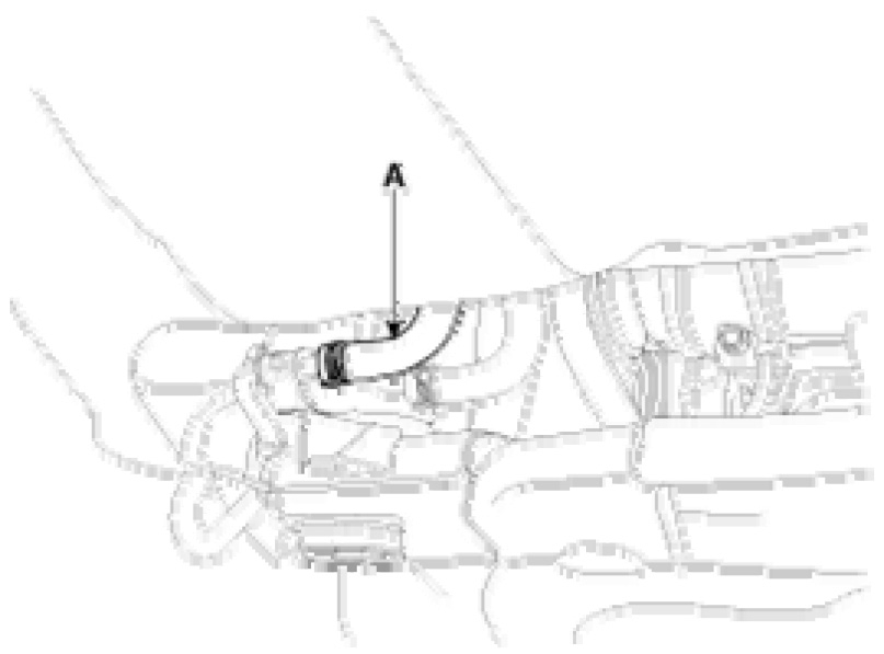
15. Disconnect the purge control solenoid valve (PCSV) hose (A).
pic 13
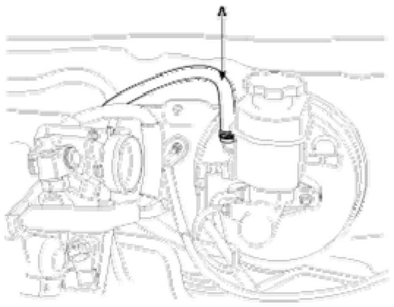
16. Remove the brake booster vacuum hose (A).
pic 14
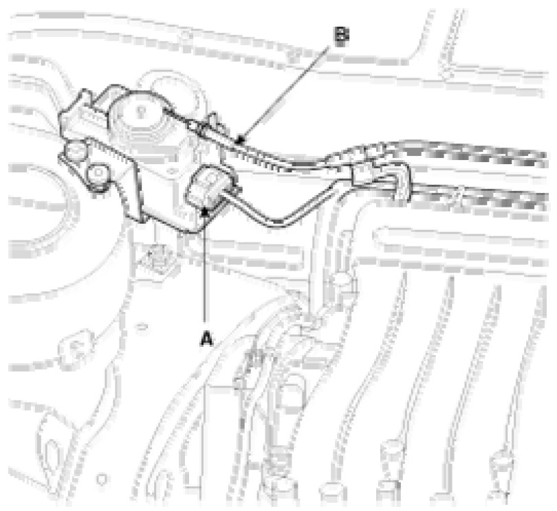
17. Remove the accelerator cable by loosening the locknut, then slip the cable end out of the throttle linkage.
18. Remove the auto-cruise connector (A) and the auto-cruise cable (B).
pic 15
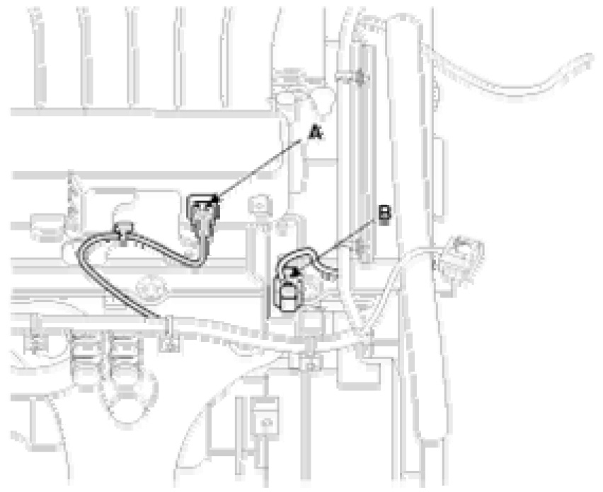
19. Disconnect the air temperature sensor (ATS) connector (A) and heated oxygen sensor (Bank 2, Sensor 2) connector (B).
pic 16
pic 17
20. Disconnect the air temperature sensor (ATS) connector (A) and heated oxygen sensor (Bank 2, Sensor 2) connector (B).
pic 18
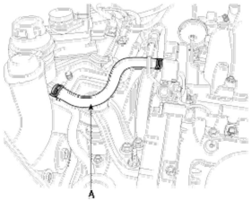
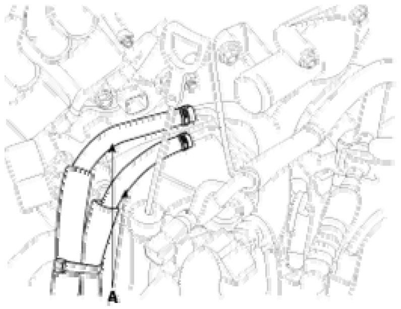
21. Remove the auto transaxle fluid hoses (A).
pic 19
22. Disconnect the transaxle wire harness connector.
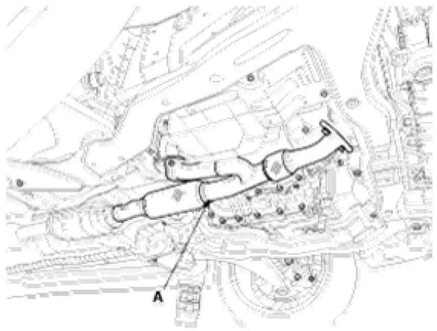
23. Remove the front exhaust pipe (A).
pic 20
24. Recover refrigerant and remove the high & low pressure pipe.
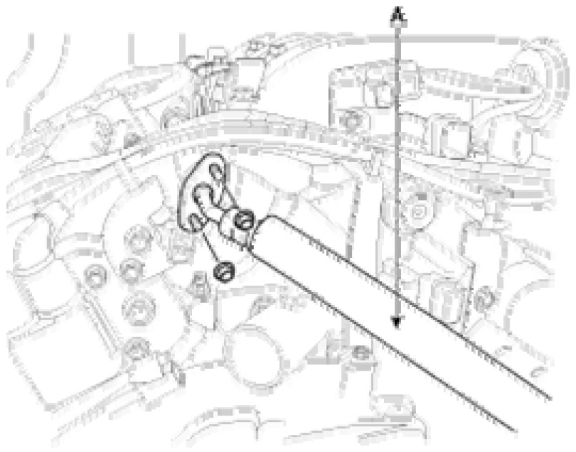
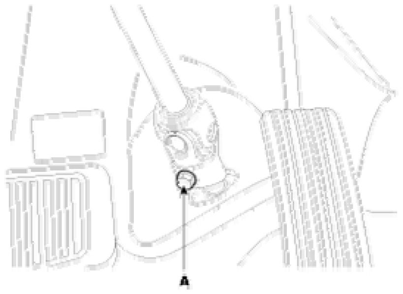
25. Remove the steering column mounting bolt (A).
pic 21
26. Remove the front wheels and tires.
27. Disconnect the stabilizer bar link and remove the mounting bolts from the lower arm and the front axles.
28. Support the engine and transaxle assembly.
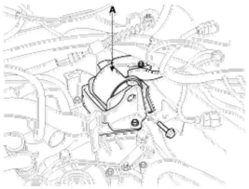
29. Remove the engine mounting support bracket (A) and the ground line (B).
pic 22
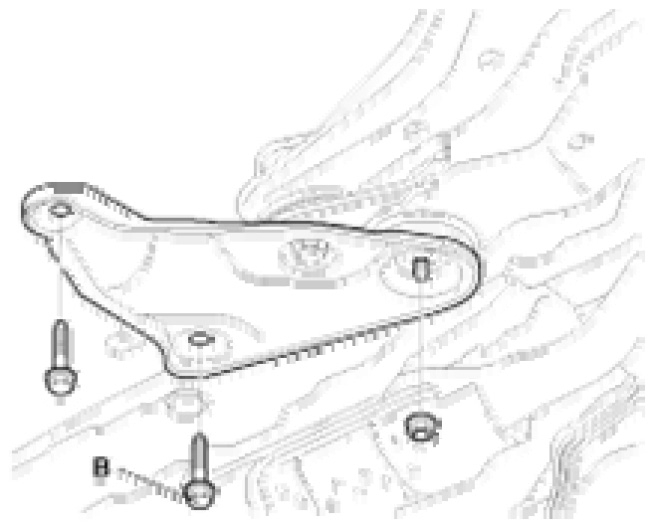
30. Remove the transaxle mounting bracket (A).
pic 23
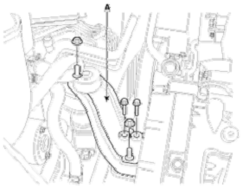
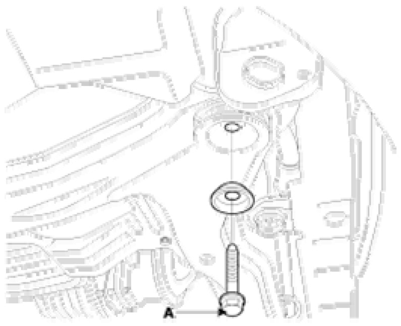
31. Remove the sub frame mounting bolts (A, B) and nut.
Tightening torque
^ A: 160 - 180 Nm (16 - 18 kgf.m, 118 - 133 lb-ft)
^ B: 70 - 90 Nm (7.0 - 9.0 kgf.m, 52 - 66 lb-ft)
pic 24
pic 25
INSTALLATION
Installation is in the reverse order of removal.
Perform the following:
^ Adjust the shift cable.
^ Adjust the throttle cable.
^ Refill the engine with engine oil.
^ Refill the transaxle with fluid.
^ Refill the radiator and reservoir tank with engine coolant.
^ Place the heater control knob on "HOT" position.
^ Bleed air from the cooling system.
- Start engine and let it run until it warms up. (until the radiator fan operates 3 or 4 times.)
- Turn Off engine. Check the coolant level and add coolant if needed. This will allow trapped air to be removed from the cooling system.
- Put the radiator cap on tightly, then run engine again and check for leaks.
^ Clean the battery posts and cable terminals with sandpaper, assemble them and then apply grease to prevent corrosion.
^ Inspect for fuel leakage.
- After assembling fuel line, turn on the ignition switch (do not operate the starter) so that the fuel pump could run for approximately two seconds and fuel line could be pressurized.
- Repeat this operation two or three times and check for fuel leakage at any point in the fuel line.
____________________________________
Let me know if this helps or if you have other questions.
Take care,
Joe
Images (Click to enlarge)
Nov 27, 2020 at 10:33 PM