Step by step method to check horn circuit needed

2011 JEEP GRAND CHEROKEE
105,000 MILES • 3.6L • V6 • 2WD • AUTOMATIC
Avatar
WELDONAB+FORUMS
  • MEMBER
  • 16 POSTS
Do you have step by step method to check horn circuit? Both horns blow when jumped at fuse. Horns do not work from steering horn button. How to check wiring at TIPM connectors?
Jun 23, 2019 at 7:12 PM
Advertisement
Avatar
SCGRANTURISMO
  • CERTIFIED EXPERT
  • 4,897 POSTS
Hello,

The information that you requested is in the diagrams down below. Testing procedures for the horn circuit in your vehicle are very limited without the use of a factory scan tool, but I have included them anyway. Please go through the guides and get back to us with what you are able to find out.

Thanks,
Alex
2CarPros
Jun 25, 2019 at 12:46 AM
Avatar
WELDONAB+FORUMS
  • MEMBER
  • 16 POSTS
Thank you for your response.
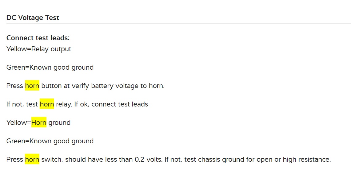
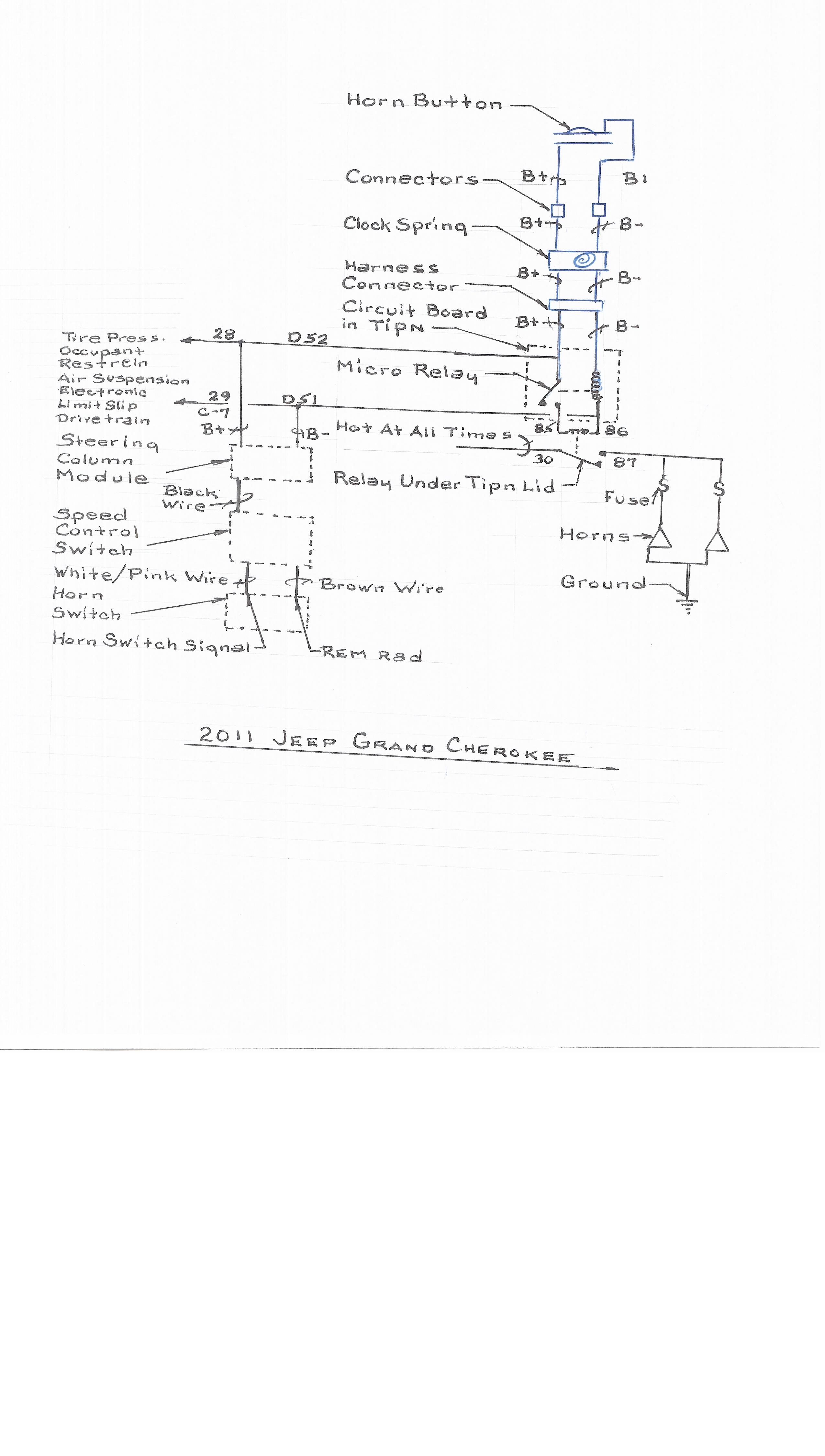
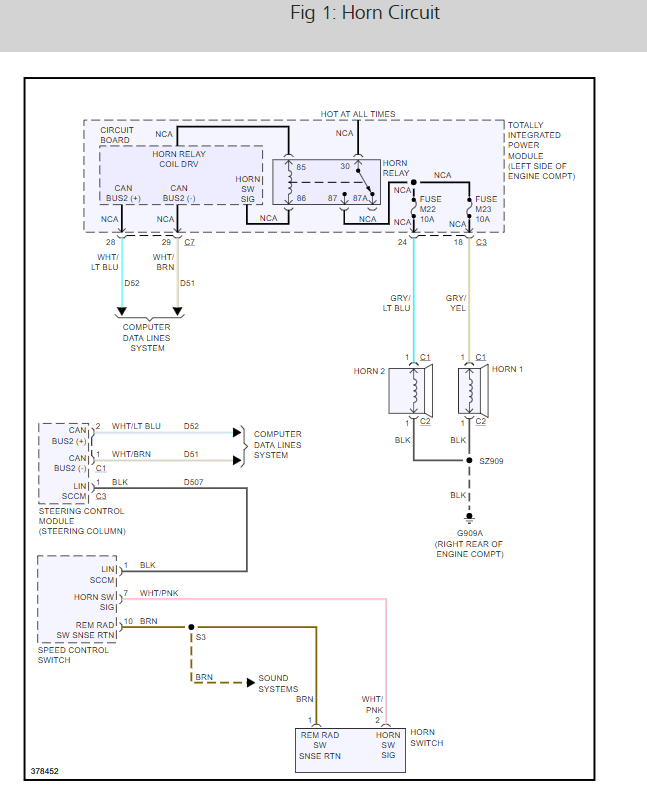
1. I need help in understanding the wiring connections on the relay (micro relay) mounted on TIPN circuit board. Have attached sketch.
2. Both horns sound with fuses removed and jumper wire from battery connected to horn side of fuse block.
3. Removed horn relay under TIPN cover and test with Ohms meter that read; 58 Ohms at coil and .3 Ohms at contacts.
4. The horn micro relay coil mounted on circuit board read 40 Ohms.
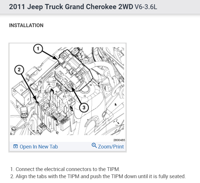
5. Would like to replace the Horn and Fuel Pump relay on TIPN circuit board being vehicle is a 2011 model. Need to research more how to.
6. Made Ohms test on connection 28, C7, to vehicle ground with horn “on” and “off”; No reading. Ohms test on connection 29, C7, to vehicle ground with horn “on and “off”; No reading. Ohms test on connection 28, C7 to connection 29, C7 with horn “on” and “off”; No reading.
7. Appreciate your support with this project.
Jun 26, 2019 at 4:58 PM
Advertisement
Avatar
STRAILER
  • CERTIFIED EXPERT
  • 53,854 POSTS
Hello,

If I can jump in. here this guide will show you how to test the wiring with the horn wiring diagrams below:

https://www.2carpros.com/articles/how-to-check-wiring

Check out the diagrams (below). Please let us know what you find. We are interested to see what it is.
Jun 29, 2019 at 5:48 PM
Avatar
WELDONAB+FORUMS
  • MEMBER
  • 16 POSTS
How to check each pin to pin’s continuity of wired ribbon within clock spring on vehicle listed above, 4 door v6 flex dohc natural aspirated? As from what connector numbered pin to what connector numbered pin there should be continuity.
Jul 9, 2019 at 10:10 AM
Avatar
STRAILER
  • CERTIFIED EXPERT
  • 53,854 POSTS
It looks like the brown and pink and white wires are the ones you want to check, doesn't really show the clock spring. You could have a TIPM that is out which is common, they are easy to replace because they self initialize. Check out the diagrams (below). Please let us know what happens.

Jul 9, 2019 at 10:45 AM