Crank no start, fuel pump relay and or circuit not working?

2010 HONDA ELEMENT
275,000 MILES • 2.4L • 4 CYL • 4WD • AUTOMATIC
Avatar
JACKKLIZ
  • MEMBER
  • 23 POSTS
Crank No Start. Checked fuel pump fuse #17 and FI ECU fuse #6 both are good. Pulled PGM-Fi relay no. 2 out and bench tested. Relay does not operate when voltage applied. Using multi meter and then double checking with test light I confirmed that while cranking engine there is voltage and ground measured at the relay socket control side. Pulled cap off of relay, placed back in socket, while cranking engine I manually "closed" relay, heard fuel pump prime and engine started and run smoothly. Bought new Honda branded relay and installed: Still No Crank No Start. Could not hear fuel pump prime. Bench tested new relay and it failed. Pulled cap off to inspect and found that diode was cracked in two. Bought second new relay, bench tests good but car does not start. Re-checked relay socket with multi meter and test light = measured voltage and test light says circuit has power and ground while cranking.
Feb 18, 2024 at 6:50 AM
Advertisement
Avatar
AL514
  • CERTIFIED EXPERT
  • 5,464 POSTS
Hello, where are you getting these relays from? the dealership or an online source? Thats pretty crazy to have a diode cracked in half like that. Try measuring the resistance of the relays control side and compare it with the other PGM FI relay 1. It might be that these are labelled as Honda parts. but are just fake branded types. We are seeing so many faulty brand-new parts these days. If the resistance of the control coils is different in the relays, then you'll know it's fake. You could also load test the power feed coming from Fuse 6 with a higher amperage test light and see if that circuit is able to carry enough current. It's a strange issue if it's not just bad parts. It sounds like you're testing correctly.
Another possibility is the control for that relay (so the grounding through the ECM) is having an issue. The relay control drivers are power transistors (mosfets) internal to the ECM and it may have high resistance through it.
You could measure voltage drop on the control pin of the relay to battery negative while cranking and see if there is any excessive voltage drop through the ECM to ground.
Feb 18, 2024 at 2:46 PM
Avatar
AL514
  • CERTIFIED EXPERT
  • 5,464 POSTS
What did the original relay look like inside? And you should also check its resistance to see if it has lower resistance than the #1 relay and compare it with the new ones as well.
Feb 18, 2024 at 3:23 PM
Advertisement
Avatar
JACKKLIZ
  • MEMBER
  • 23 POSTS
Hello AL514, and thanks very much for your help. I will perform the tests mentioned later this coming week and let you know the results.
Thanks again!
Jack
Feb 18, 2024 at 5:38 PM
Avatar
AL514
  • CERTIFIED EXPERT
  • 5,464 POSTS
Sounds good. Just make sure that you don't apply battery voltage to the relay's control wire, since it's a ground side controlled relay, applying power to it will damage the ECM's internal driver. This is a basic diagram showing how the relays are controlled inside the ECM. The transistors are low current control devices, so if a relay was to short out or power was applied directly to the control side of the relays, the transistors can burn out. It happens more with ignition coils, but I just wanted to show a simple description of how the relays are controlled.

https://www.2carpros.com/articles/how-to-check-an-electrical-relay-and-wiring-control-circuit
Feb 18, 2024 at 8:03 PM
Avatar
JACKKLIZ
  • MEMBER
  • 23 POSTS
Hello AL514, Results of tests this morning: Resistance test control side pins of relay PGM-FI #1 is 107.4 ohms; relay PGM-FI #2 is 48.4 this being the relay with broken diode bought new from Hondapartsnow.com. Second new relay from Carquest measured 51.9; the original relay from car measured 1.7 ohms. Voltage drop test control side pins PGM-FI #2 relay in socket. Ground cable to neg. post battery, positive test lead of multi meter to pin #5, ignition key to “On” 12.3 volts, cranking engine 10.3 volts. Then test lead to pin #3 key “On” 11.67v, cranking 10.0 volts. Inspected inside of original relay #2 cap off: no observable damage to coil, diode and pins. Original relay does not operate when voltage applied to pins 5 and 3. I did not load test power feed from Fuse 6 admittedly I don’t know how to do this. If I tested things correctly, please let me know your thoughts when you get time. Thanks very much for your help!
Feb 24, 2024 at 7:39 AM
Avatar
AL514
  • CERTIFIED EXPERT
  • 5,464 POSTS
The original relay only measured 1.7ohm!? Thats not good. and your test result reveals that you have 10.3 volts of voltage drop from the relay location through the ECM. The resistance of the original relay shorted out, and it sounds like it may have damaged the ECM driver for the relay. Your voltage drop test on pin 3 should have gone to 0volts, or very close to it. Because the ECM pulls the 12volts to ground to operate the relay. Both of the two new relays should have the same resistance as the #1. Since they are basically the same relay,
Is there a part number on the original relay, I want to look it up, and there isnt a part number on All Data. Next, we need to test at the ECM to make sure there isnt a damaged wire coming from pin 3. Since you did a voltage drop test, which is the correct method, a damaged wire can cause those readings as well.
So, if we divide 12volts by the resistances of each relay, 12.4/107.4= 0.114 (114ma) is what operates relay #1. But you can see 12.4v/1.7ohms = 7.29 Amps of current, that's way too much for that driver inside the ECM. I'm going to pull up the ECM connectors for you, so you can do the same test at the ECM wire from pin 3.
Feb 24, 2024 at 9:47 AM
Avatar
AL514
  • CERTIFIED EXPERT
  • 5,464 POSTS
Okay, so in service info here, I finally found the ECM connector E which is where the PGM FI relay 2 control wire goes to, But they do not list any color or anything to identify the connector, so what you have to do is verify the correct connector by the wire coloring, I will post the diagrams in a minute here when I get them sorted out, the ECM is behind the glove box, so you will have to take that out if you haven't already, I think the PGM FI relays are back there as well?
Feb 24, 2024 at 10:03 AM
Avatar
JACKKLIZ
  • MEMBER
  • 23 POSTS
Hi AL514, Thank you tons! The original relay cap says: Mitsuba RC-5104 and may also be known as 39794-S5A-003
Feb 24, 2024 at 10:16 AM
Avatar
AL514
  • CERTIFIED EXPERT
  • 5,464 POSTS
Okay, no prob, it's just Al BTW =) The 1st diagram is the other ECM connectors A, B C, D. Not sure why they don't list them all together, I had to search for connector E, but it's in the 2nd and 3rd diagrams, showing pin 17 green/yellow wire. I am kind of surprised, this is the 1st Honda relay I have seen potentially take out an ECM driver, I hope that it didn't.
Even the 2nd relay you bought at 48.4 ohms is going to draw 256ma, that's really the limit on how much a relay should pull for amperage, I usually find relays to be around 75ohms, although I haven't checked any Honda relays like this before. Most of the time with these they just fail on the load side, and don't work, So I'd just check it one more time to be sure it's really 1.7 Ohms, not that I don't believe you, it's just odd. I do see that parts are failing much more in the last 10 years than ever before, the quality is just gone way down.
The 5th diagram is just a part number I found on rockauto. The pinout for the PGM FI relay 1 and 2 is different though.
We should go through and very all powers and grounds for the ECM before condemning it. To make sure there isn't a bad ECM ground, I also now questioning the Fuel pump, if its drawing excessive current and overheated the relay,
I like to know why something failed like this, so it does happen to any new parts as well.
Feb 24, 2024 at 10:43 AM
Avatar
AL514
  • CERTIFIED EXPERT
  • 5,464 POSTS
Did you happen to scan the ECM for any diagnostic trouble codes?
With a fuel pump failure, or suspect, we would check the current draw on the pump, as well as scope the pump's current pattern and check its rpms. You would need an amp clamp to check the current draw on a fuel pump. There are also multiple connectors on this PGM FI circuit diagram,
This is connector C451 and its location down by the gas pedal, if you want to check that, I'm going to also look up the connectors going to the fuel pump and its Ground. You could check the resistance from Relay 2, pin 2 to ground, which would give you the resistance of the Fuel pump and its circuit. it should be pretty low.
You mentioned you jumped the relay out and the vehicle ran, how long did you run it for, and did the jumper lead you used get really hot while it was running?

I've added a couple things here, has any liquids been spilt on the center console where the Parking Brake lever is, (and Connector C558)?
And then diagrams 6-8 are Recall notices on the Airbag system, just thought you should have these.
Feb 24, 2024 at 10:44 AM
Avatar
JACKKLIZ
  • MEMBER
  • 23 POSTS
Hi Al,

With my “Actron CP9125” OBD II Pocketscan I didn’t read any DTCs. There hasn’t been a Check Engine light either. When I jumped the fuel pump relay and ran the engine I only let car run for a minute or so. I didn’t check jumper wire. Later this afternoon I plan on starting and letting it run for longer duration; will check jumper wire for heat. No liquid spilled near parking brake. Right before Element first failed to start we had several days of below zero weather. It is kept in heated garage but was driven during cold. I will attempt to check resistance from relay pin #2 to ground when I work on it again. Thanks again for your help, Jack
Feb 24, 2024 at 12:31 PM
Avatar
AL514
  • CERTIFIED EXPERT
  • 5,464 POSTS
Okay, do you own an amp clamp? I've posted this case to some other technicians to see if any Honda techs have seen these relays short out like this, and what could have potentially caused it. If it turns out that the ECM has burned the driver for the relay, we really need to figure out why, so it doesn't happen again. I do repair modules on the side, but that depends on what I find when they are opened up. So that's a possibility,
If you have an amp clamp that can read dc current, you can measure around the jumper wire you use to see how much current the pump is pulling. Just use at least a 14-gauge wire so it doesn't melt. 14 gauge can handle about 10-15 amps, but the pump should only pull around 5-8amps max.
This is part of the Flow Chart for diagnosing an issue with the fuel pump circuit. Most of this you have already done. At step 17 if there is battery voltage at the ECM connector E pin 17 (which is the Relay 2 control wire), they say substitute a known good ECM. Which we shouldn't do until you get a relay from Honda, and we check the ECM's powers and grounds. Computers are too expensive to just try as a diagnostic strategy. But you can do the wire checks here, let me know what you find.
Feb 24, 2024 at 1:20 PM
Avatar
JACKKLIZ
  • MEMBER
  • 23 POSTS
Hi Al,

I don’t have an Amp Clamp, but I’ll check with a friend of mine at work this Monday and see if he has one. I appreciate your help with this problem.
Jack
Feb 24, 2024 at 4:34 PM
Avatar
AL514
  • CERTIFIED EXPERT
  • 5,464 POSTS
Okay, it's possible the relay just failed, and took out the ECM, but leaving it at that is not a diagnosis. I'll chat with you Monday then.
Feb 24, 2024 at 6:36 PM
Avatar
JACKKLIZ
  • MEMBER
  • 23 POSTS
Hi Al,

I have printed all the wiring diagrams with your instructions and plan on continuing to work on the car this coming weekend. Thanks for patience and expert help.
Jack
Feb 28, 2024 at 6:26 PM
Avatar
AL514
  • CERTIFIED EXPERT
  • 5,464 POSTS
Okay, I contacted some other technicians as well on this case, and they said the same thing, to check on how much current the fuel pump is drawing, possibly overheating the circuit and hence the relay. The relay contacts that close, which is the load side of the relay that powers the pump, those contacts are a point of resistance in the circuit which is normal, they open and close which you saw when you took it apart. Do you notice if the relay pins look overheated, discolored or anywhere on the relay where the plastic bubbled up from heat? The vehicle does have super high mileage. A fuel pump with lower-than-normal resistance will cause more current to flow but usually cause the fuse to blow, but if the relay is not making good contact at the pins, that's resistance in the circuit and would cause it to overheat. I just don't want to see you replace the ECM and relay, just for it to burn up again.

The Powers and Grounds of the ECM should be load tested with a few amp lamp bulb. The fuel pump is fed by a 15amp fuse, To load test a circuit, I use a turn signal bulb set up that I know pulls 4-5amps, So I will check a wire coming directly from a fuse, not pulling that much amperage through the ECM, just checking with the ECM connector unplugged, I'll do the same to check the Grounds, I'll power up the bulb and whatever ground I'm testing will be the lamps ground. Again, not going through the ECM. So, you have to know exactly where the power is coming from and be 100% sure of what you're doing before doing load testing like this.
But check the fuel pumps current draw first and see what's that is, also get a relay that is the correct resistance. Go to a Honda dealership and explain what happened so they can give you a decent relay, and then I can walk you through checking all the ECM powers and grounds before replacing it. The dealership might have some suggestions for you as well.

This is the response from the other tech. But it sounds like the shorted relay probably burned out the transistor that grounds the relay control side. If you want to check fuel pressure, the spec is 48-55psi. On this fuel system you have to T a fuel pressure gauge into the fuel line.
But with this high mileage, you're going to start running into one issue after another unfortunately. I see this a lot and work on a lot of really high mileage vehicles. Let me know what you find, and we'll go from there. Here are a couple guides and the relay OEM part numbers, but I think something else is going on here.

https://www.2carpros.com/articles/how-to-check-fuel-system-pressure-and-regulator

https://www.2carpros.com/articles/signs-of-a-clogged-fuel-filter-in-your-car-symptoms-to-watch
Feb 28, 2024 at 8:09 PM
Avatar
JACKKLIZ
  • MEMBER
  • 23 POSTS
Hi Al,

Here are results and information from working on Honda Element this weekend:
I installed 14ga jumper wire to pins #1 and #2 of PGM-FI Relay 2; car started immediately an.
Mar 3, 2024 at 10:40 AM
Avatar
JACKKLIZ
  • MEMBER
  • 23 POSTS
Oops I hit the Reply button by mistake!
The element started immediately and ran smoothly for ten minutes. Jumper wire did not get hot or even warm. I did not get hold of an Amp Clamp, so I measured DC current draw of fuel pump by using multimeter. Set meter to 10A dc, (+) lead to #1 connector terminal & (-) lead to #2 terminal of Fuel Pump relay socket; so the Multi Meter was acting as the "Jumper wire"; Acceptable way to test? Started engine and let idle for about two minutes; read 3.60 amps on meter. Next I unplugged ECM connector E and measured Good Continuity between terminal #3 of relay socket and terminal #17 of Connector E. I then measured 1.8 ohms resistance of same wire. Visual inspection of original fuel pump relay shows no sign of discoloration or heat damage anywhere. I tried to do the "Back Probe Voltage Drop" test from pin 17 of Connector E to vehicle ground: measured 11.2v when I turned key to ON (II) then start position measured 9.8v; there was no 2-second interval of 0 volts observed when I first switched key to ON (II). Have been keeping battery on trickle charger and measure 12.6v at battery terminals. I had the Carquest brand relay in place during this last test as I have not bought a proper Honda relay yet. I believe that I must get this new relay and try the voltage drop test again. Does this sound correct?
Mar 3, 2024 at 11:18 AM
Avatar
AL514
  • CERTIFIED EXPERT
  • 5,464 POSTS
Yeah, that's just bypassing the relay Load side, I'm concerned the control side being shorted out, burned out the ECM control side. If you look down at E17 on the ECM, you'll see that it says "(IMO FPR) Fuel Pump Control". So, it looks like that circuit is used for the Immobilizer as well as the Fuel pump control. If that is part of the Immobilizer circuit, that's the security system's way of disabling the vehicle. It simply will not turn on the fuel pump. The ECM grounds that circuit to activate the fuel pump once power is applied to PGM FI relay #2 from relay #1. So, it depends on how much you want to spend to repair this the correct way. Which includes getting a new relay that is the correct resistance (107ohms or around there like the other relay is) plus checking all the powers and grounds of the current ECM, and then replacing it. And hopefully there are no other circuit issues that will damage the new ECM. Did you get a current measurement for the fuel pump?
Mar 3, 2024 at 11:18 AM
Avatar
JACKKLIZ
  • MEMBER
  • 23 POSTS
Thanks for the fast reply. I mentioned the 3.6 amps measured with the multimeter is that what you were asking for?
Jack
Mar 3, 2024 at 11:48 AM
Avatar
AL514
  • CERTIFIED EXPERT
  • 5,464 POSTS
Okay, looks like our replies got crossed there. 3.6 amps is pretty low for a fuel pump. You did all the tests correctly, one thing I would add, is when doing your resistance check from pin 3 of the relay socket and the ECM connector unplugged to pin 17, with both the relay out and the ECM unplugged, I would check from either pin 3 or 17, it doesn't matter, check for any continuity to Ground. This will verify the wire is not shorted to ground anywhere in between the relay location and the ECM. Your meter should read OL when measuring for resistance to any Ground.
With your voltage drop test, you didn't have any 2 second fuel pump prime, or control of the relay at all. And measuring 11.2v and 9.8v, that's how much voltage is being lost between your meter leads. Or the technical term is "potential" between the 2 leads.
I would expect the fuel pump to draw about 6 amps, even up to 10 amps on some higher-pressure systems. So that pump reading is concerning. I will see if I can find a spec on that, but it's a low reading. I think the fuel filter is in the tank with the pump, but I'll look that up as well. But check that circuit for any resistance to ground. and I'll get back with you.
Mar 3, 2024 at 12:30 PM
Avatar
JACKKLIZ
  • MEMBER
  • 23 POSTS
Hi Al. I believe I understand the “checking for short to ground test” Will try this and reply. Thanks
Mar 3, 2024 at 12:53 PM
Avatar
JACKKLIZ
  • MEMBER
  • 23 POSTS
Unplugged relay and ECM E connector then checked pin 17 for continuity to ground and read open on meter. Double checked from relay socket pin 3 to ground and confirmed open.
Jack
Mar 3, 2024 at 1:08 PM
Avatar
AL514
  • CERTIFIED EXPERT
  • 5,464 POSTS
Okay, that's good, looks like the circuit is intact. That pretty much leaves us with two possibilities, either the #2 relay just failed on its own and that took out the ECM. Or the fuel pump is struggling and overheated the relay causing it to fail.
Since we are not 100% sure on the pump here, and corroded connections can cause heat buildup, we need to check a few more things. It was a wise move the keep the battery on a maintainer during key on testing.

But the next part is going to be a pain. Getting access to the pump connector to check for voltage drop from the Fuse (17 15amp) that feeds the fuel pump through relay #2, all the way to the fuel pump, since you can access it without dropping the tank. This is the Fuse box under the dash so it shouldnt be too much of a stretch. I've added the aftermarket diagrams 1,2, then the OEM 3, and the 4th is the connector at the Fuel pump itself.

Service info here is stating you need to remove the center console to get to the fuel pump access cover, because the cover is under the rear floor carpet, but you may be able to get to it without having to remove the entire center console, that's a lot of work here. I'm not sure if you have attempted to get to the pump yet, but I've added all the instructions to replace the pump, but for right now, we just need access to the fuel pump connector in diagram 6, so you can check for any voltage drop to the (pump pin 5) to Fuse 17.
And then also check for voltage drop on the pumps ground which is pin 4 to Ground, while you have it running. There needs to be current flowing for any voltage drop to occur.

But if there's not excessive voltage drop on the power feed or ground, you will have to check the fuel pump itself for signs of overheating. There could be issues with the connector at the pumps cover or in the tank as well. If you can't get to the cover by removing the rear carpet and need to the instructions for the center console to come out, Ill pull those up for you. YouTube may have a video for it as well, which ill check. It looks like a lot to pull that console out.

Id get your meter and leads set up first and then jump the relay and start the vehicle. Since we do have a few connectors in series with the pump.
If you go to a Honda dealership to get a relay, tell them how much the pump is drawing for current flow, and see what they say about it. Its definitely low to me, so this could all have been a domino effect leading to the relays failure. Sorry for the long post, I just don't want to see a new ECM fail in a couple months or less.
Mar 3, 2024 at 3:17 PM
Avatar
JACKKLIZ
  • MEMBER
  • 23 POSTS
Hi Al,

I plan on buying a new relay from local Honda dealer this week. Sorry that I am taking so long to do the tests you’ve given me, but I don’t have much free time during the week and this car is not our main vehicle. We do want to fix her. I’m thinking that I should buy an amp clamp to redo the current draw test. Would this be more accurate than my multi meter alone? Thanks tons to you and 2carpros!
Mar 3, 2024 at 5:54 PM
Avatar
AL514
  • CERTIFIED EXPERT
  • 5,464 POSTS
It's okay, take your time with testing, if you're not in a rush, I'm not, I have mobile calls to go on today, hence my slow responses sometimes. Your multimeter being in series with the pump will read up to 10-Amps max, and usually only for about 15 seconds, or whatever is says on the meter itself, they are all different. Some have a 10 Amp fuse inside for checking current draw. I know one of my multimeters has a warning on the current reading, I believe it's a 15 second current reading followed by a 15min cool down time, so it really just depends on what the meter says on it. If it has a good battery in it, I think it's most likely accurate, if you doubt that it is, you can buy an amp clamp, they're great to have, you can check all kinds of components with them. Just make sure the one you buy is not designed for home installations only, it has to be able to read DC current, I know a lot of the ones that Lowes for example sell, are for AC current. You could try Harbor Freight, they have quite a few decent tools for testing that are not overly expensive.

The amp clamps I use are very expensive, but that is because they are designed to work with my Pico scope setup, so I can watch the current or voltage waveforms. But you only need to know what the pump is drawing for current. It would take forever to explain using an oscilloscope. Do mention the current reading you got when at the dealership; I'd be interested in what they have to say on it. The vehicle has very high mileage, so it might need a fuel pump as well. I tend to see these types of situations a lot (because I work on a lot of very high mileage vehicles), but it's where one failed component will take out a couple other components. Which is what sounds like happened here.
This happens sometimes with 2 wire ignition coils as well, since it's just one wire for power and the other wire goes directly into the ECM/PCM, when the coil shorts out, it will send excessive current flow through the computer and burn out the transistor driver. I did post this case to other techs to see what they think about the pumps current, and I'll let you know what responses I get. Sometimes a Honda tech will chime in and give some good advice.
Chat soon.

Al
Mar 4, 2024 at 8:16 AM
Avatar
AL514
  • CERTIFIED EXPERT
  • 5,464 POSTS
Okay, I received some responses to this case, now besides the negative comments that always come from some guys, one of them was willing to be reasonable. Now Im not sure I agree 100% on everything he stated, because components do short out and cause damage. But he seemed to think that if the relay shorted out, the ECM would have deactivated that circuit and set a code, which we didnt see happen. He suggested having you recheck for any power on the relay's pin 3 circuit with the ECM plugged in again. For whatever reason, no one seemed to really take into consideration the low resistance of the original relay, which really bothered me.

But to just verify what he was saying, using an automotive test light hooked to battery negative and the ECM connector plugged in and key On, see if relay pin 3 lights a test light at all. Doing this might set a code in the ECM, but thats ok for now. We just need to know if power is shorted to that wire in some other location.
The other thing he was suggesting was the Immobilizer was active and causing the ECM to prevent grounding the relay and activating it. So depending on the type of scan tool you have, a higher end scan tool will be able to look at live data in other modules in the vehicle. And in turn, look into the Security system module to see if there are any data PIDs indicating the security system is preventing the relay from activating. i think you would also see the security light staying on when trying to crank it over, but that also depends on if the immobilizer system was faulting or the key was bad, etc.

The first two diagrams below are for identifying an Immobilizer issue or being active by the security light flashes or lack of. I assume the Check engine light comes on at Key on, because you are able to start the vehicle with the relay jumped out.
The 3rd diagram is the Immobilizer Log Status, which you may or may not be able to look into, again depending on your scan tools capabilities. It will indicate if any faults are detected and log them, like any computer would normally do. "0" is none, and "1" would be a fault detected.
Since the Immobilizer uses the fuel pump control to prevent the vehicle from starting, we will humor them and check it. So if you get any of the Security lighting patterns 2-5 or the Security light does not come on at all.

He had mentioned the same thing about being absolutely sure about an ECM failure before replacing it, and I agree with that. And Im sure you tested the relays resistance correctly. When you opened that relay up, I assume it had a resistor inside. Most relays have either a diode or resistor inside the relay or in series with the power feed of the relay to help with the transient high voltage that occurs when the relay is deactivated.

But start here by checking with a test light for power on pin 3 with the relay out. I know we did a voltage drop test across the ECM and ground, but using a test light will show there is a solid power source shorted to ECM connector E pin 17. And that would cause the ECM driver for the relay to burn out. Im going to look into some of these symptom related procedures.
Mar 6, 2024 at 10:55 AM
Avatar
AL514
  • CERTIFIED EXPERT
  • 5,464 POSTS
Go ahead and grab two new PGM FI relays and replace both of them with only Honda OEM parts from the dealership. And go from there. If it's still a no start condition, then go ahead with checking for any power on pin 3. That way we know at least both are functioning okay. It's possible the ECM is shutting down the #2 relay circuit if the new relays are low on resistance as well. just thinking about this some more, I have never seen a Honda relay cause an ECM failure.
Mar 6, 2024 at 3:33 PM
Avatar
JACKKLIZ
  • MEMBER
  • 23 POSTS
Hi Al,

I will check with my Honda dealer yet this week about two new relays as well as following your testing instructions. I have an amp clamp on the way too.
Thanks,
Jack
Mar 6, 2024 at 3:41 PM
Avatar
AL514
  • CERTIFIED EXPERT
  • 5,464 POSTS
Okay, sounds good. Let's hope this is just a bunch of bad relays. The low fuel pump current sent me over thinking things a bit. Might still be an issue, but this vehicle has extremely high mileage. and they always seem to have more than one problem. Everything wears out eventually.
Mar 6, 2024 at 3:47 PM
Avatar
JACKKLIZ
  • MEMBER
  • 23 POSTS
Hi Al, here are the test results so far:

1) with new Mestek CM83E clamp meter read 8.65 amps around jumper wire while engine running. Ohms resistance from Pin 2 of PGM-FI #2 socket to body ground =2.0 ohms.
2) checked for Immobilizer Light Pattern: Observed Normal Operation (Lighting Pattern 1) of Green Key light on dash.
3) re-checked for DTCs = none read.
4) Fuel Pump Unit 5P Connector measured Good Continuity between terminal #4 and body ground. Measured 1.8 ohms resistance of same wire/ Terminal #4 to ground.
5) Fuel Pump Unit 5P connector measured no voltage from Terminal #5 to body ground as key was turned to On(II) Note: Carquest Relay in socket, no new Honda relay yet. Tested again w/ jumper wire in place of relay then measured 12.07 volts key ON (II)
6) Re-checked voltage at relay pin 3 to E17 circuit, w/ ECM E connector plugged in, using Test Light, relay not in socket, turned key to On (II) probe point to Pin 5 socket & probe clamp lead to Pin 3 socket = the test light lit up "Red" for positive polarity.
I hope I have done these tests correctly. Please let me know if I missed doing a test and what your thoughts are when you get time. Thanks!
Mar 13, 2024 at 9:59 AM
Avatar
AL514
  • CERTIFIED EXPERT
  • 5,464 POSTS
Okay, yes you did the tests correctly, you're getting substantially higher voltage now for the pump huh. I wonder if your multimeter battery is low. And the one thing that's odd is the voltage on the control side of the relay with it out.

So, unplug the ECM connector and recheck with the test light for voltage. This way the ECM is out of the equation. There might be a power wire shorted to the relays control wire to the ECM. Thats what we need to know next. If so, we'll need to track down that short.

Somethings you might see that can be deceiving, with the ECM connector unplugged, there may or may not be voltage on the control wire (pin 3). This depends on where that voltage is coming from. If its something related to the ECM connector being plugged in, the stray voltage may disappear during this test.

Ill bring up service info again and see what else is on connector E, but you've got you're testing down well, for sure. I'm glad to see that higher amperage from the pump. That really threw me off for a minute. But if that voltage is a shorted power wire, sending voltage down into the ECM on the relays control wire, that can potentially burn the ECM driver. Do that test and see if the test light doesn't light up anymore.
Was the test light really bright? I think you mentioned you were reading 11volts at some points on that wire. Sometimes a power short will only dimly light a test lamp.
This ECM has 5 connectors, correct?
Mar 13, 2024 at 11:27 AM
Avatar
JACKKLIZ
  • MEMBER
  • 23 POSTS
Hi Al,

The test light was bright, and the ECM does have 5 connectors. Just re-did test with ECM E connector unplugged = Test Light did not light up at all when connected to pins 5 and 3 and key On (II).
Jack
Mar 13, 2024 at 12:43 PM
Avatar
AL514
  • CERTIFIED EXPERT
  • 5,464 POSTS
Hook the test light to Battery negative (or any Ground but make sure the test light is grounded good by touching a power source) and with the ECM E connector plugged in (relay out) touch pin 3 with the tip of the test light, key off and then key On.
Sorry I should have been more specific about this.

We need to look for stray power on that wire. If it lights, then unplug the ECM connector E and retest the same. Not involving pin 5 at all.

We are looking for a short to power on the wire from pin 3 to the ECM connector here. Not a short to ground, you already verified that with your continuity test.
I apologize, I always have multiple things going on during the day.
Mar 13, 2024 at 1:22 PM
Avatar
JACKKLIZ
  • MEMBER
  • 23 POSTS
Results: ECM E connected and relay out = No Light when testing pin 3 and ground both with key Off and key On.
Mar 13, 2024 at 1:51 PM
Avatar
AL514
  • CERTIFIED EXPERT
  • 5,464 POSTS
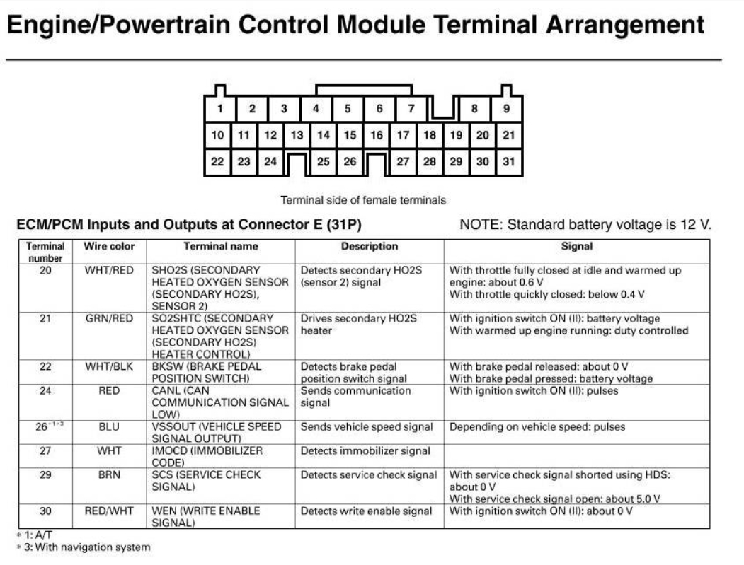
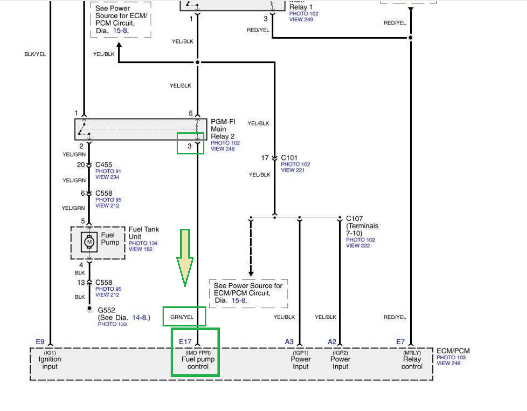
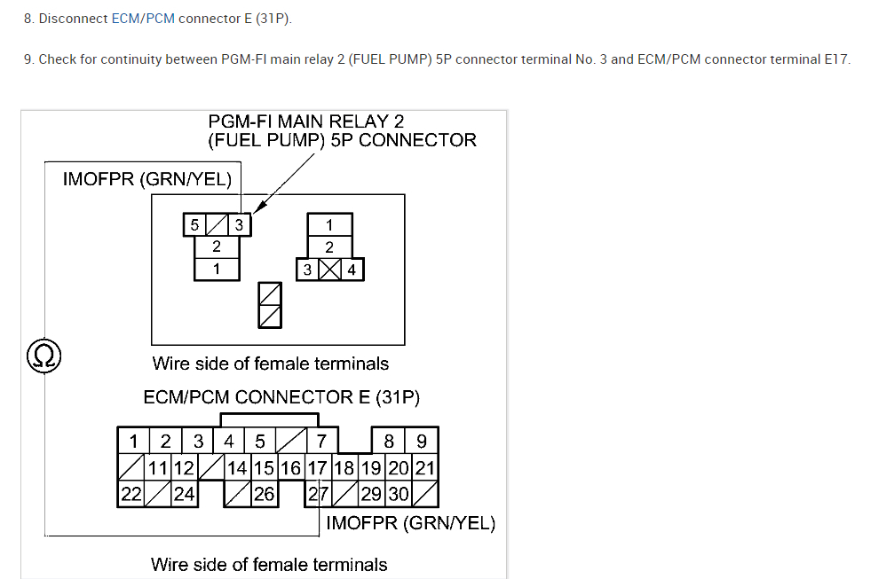
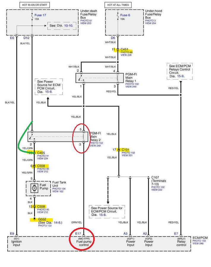
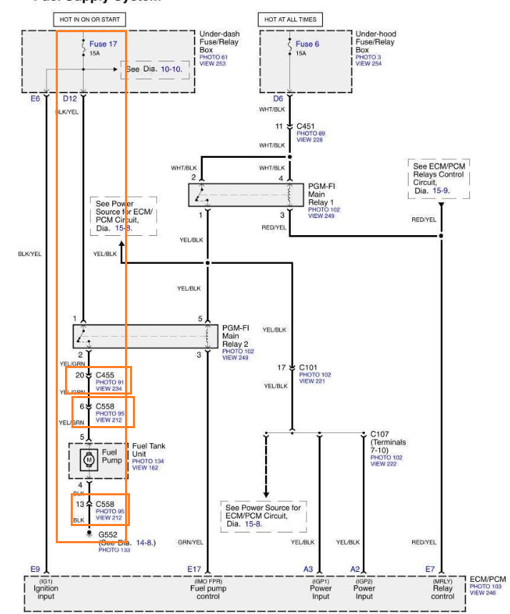
Okay last test for today, and then try a couple new OEM Honda relays. Same test, just with the ECM connector E unplugged. Test light hooked to Ground and touching with the tip to pin 3 with key Off, and key On. That will verify there's nothing internal to the ECM that could be limiting current flow preventing the test light bulb from illuminating.

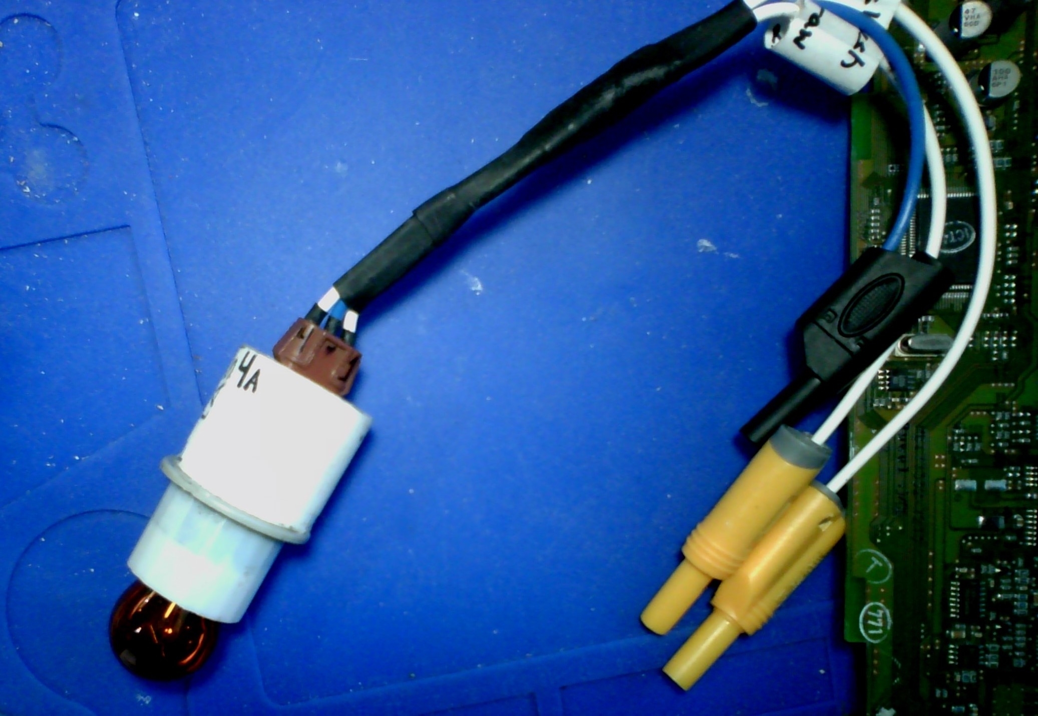
Pretty much after this, we will try the new relays with the correct resistance. If things don't improve we'll need to load test circuits. This is what I use for load testing (pic), it's a turn signal bulb with 2 filaments. One filament is 4 amps, and the other is about 1 amp.

To load test a circuit, (an ECM ground for example), the load test light will be hooked to battery positive, then I'll disconnect the ECM connector and use its Ground wire in the ECM connector to ground my load tester, if the lamp lights, I know that ground circuit can carry either the 4amps or the 1amp, depending on how much load I want to put on the wire.
At the same time, I will voltage drop that wire with the load on it, having the multimeter hooked in parallel with the load test light. So, if the test light does not light, I'll know what the voltage drop is on that ground wire.

The same can be done with a power feed, you just have to make sure you're not pulling those 4 amps through the module (ECM is this case). You're only going from its connector to power or ground source.
This test must always be done before condemning any modules. Along with any inputs or outputs checked to make sure there isnt something else causing the ECM to act strange, not activating components/circuits.

The reason for load testing power and ground feeds is that normal test lights only pull a few hundred milliamps and that is not enough to verify wire integrity. Even with a resistance test, there can be just one strain of wire left, and that will check out as zero ohms of resistance, but it will not carry enough current for the module to operate.
We will also need to load test the pin 3 to E17 wire. Although relays only pull about 200ma at most.

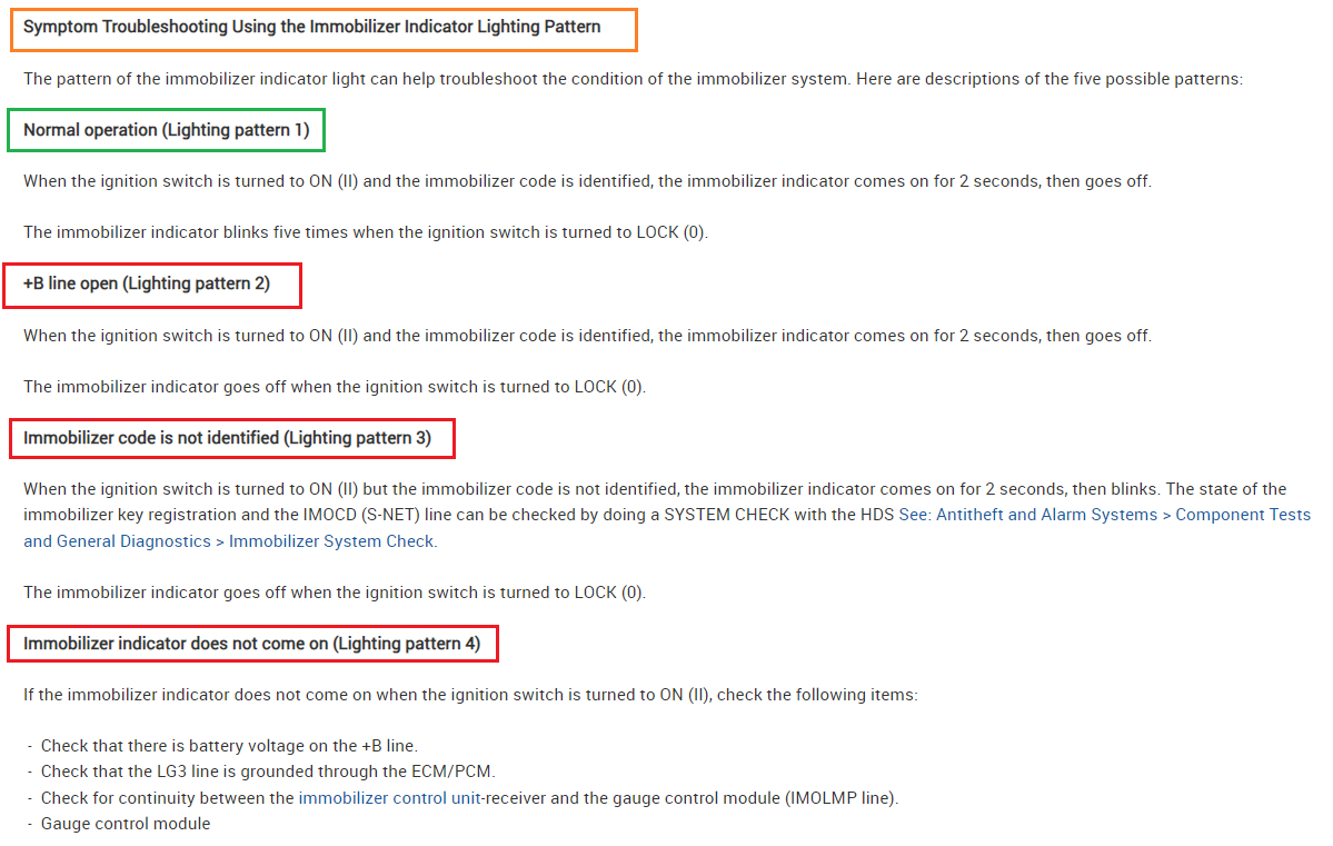
I assume when you turn the key On, the security light only comes on for 2 sec then goes out? I've had others suggest checking the Immobilizer or ECM live data for any data PIDs having to do with the security system. One was pretty sure this was an Immobilizer fault, but the scan tool you have can't access the security system module, so that is tricky part here. Since the circuit we are dealing with is the IMMO circuit.

I'll post a diagram for you showing exactly how to do this, because if you accidentally pull 4 amps through a module it will be damaged. Another long post today.
Mar 13, 2024 at 2:44 PM
Avatar
JACKKLIZ
  • MEMBER
  • 23 POSTS
Results: Connector E unplugged, no light key Off and no light key On. Security light “Green Key” on for 2 seconds then off when ignition key switched On. This is the Immobilizer Light Pattern One I believe. Thanks, as always, for your help. Jack
Mar 13, 2024 at 3:06 PM
Avatar
AL514
  • CERTIFIED EXPERT
  • 5,464 POSTS
I think it's Security pattern 1 also, but I got 2 guys that insisted it was an IMMO issue, so we'll try two new relays and go from there. They seemed to disregard the fact that the relay was shorted out, I know some modules have protection from short circuits, but I've seen plenty of failures too.
Mar 13, 2024 at 4:06 PM
Avatar
JACKKLIZ
  • MEMBER
  • 23 POSTS
Hi Al,

Called local Honda dealer today; they will have the two new PGM-FI relays for me tomorrow morning (3/15/‘24) Will get items to make Turn Signal bulb test light from auto parts store too. Is it safe to put new relays in and try and start? Or should I wait until you direct me to do so?
Thanks, Jack
Mar 14, 2024 at 2:05 PM
Avatar
AL514
  • CERTIFIED EXPERT
  • 5,464 POSTS
Yes, try the 2 new relays first, let's see what happens. I'm not usually a parts changer, but in this case, we don't really know if this ECM will shut down a circuit like this in time to prevent damage. Plus, it did not set any codes, which if there was circuit protection like that, it should have. Try the relays even before making up a load test light, let's see if these other guys were right, clear any codes out before trying to start it if there are any set.
Mar 14, 2024 at 2:14 PM