Crank not start, fuel pump relay does not engage?

2001 CHRYSLER TOWN AND COUNTRY
140,000 MILES • 3.8L • V6 • 2WD • AUTOMATIC
Avatar
CHRYSLER 01
  • MEMBER
  • 68 POSTS
My fuel pump relay doesn’t engage when I turn the key on. no crank no start.
May 17, 2025 at 9:18 PM
Advertisement
Avatar
CHRYSLER 01
  • MEMBER
  • 68 POSTS
for the record the fuel pump itself works, when I jump pin # 30 and #87, just not turning with the key.
May 17, 2025 at 9:25 PM
Avatar
CARADIODOC
  • CERTIFIED EXPERT
  • 34,306 POSTS
It's not supposed to turn on just with the ignition switch on. That would create a huge fire hazard in the event of a crash that ruptures a fuel line. Instead, it should turn on for just one second, then turn back off until the Engine Computer sees engine rotation, (cranking or running). It knows that by the signal pulses it receives from the crankshaft position sensor and the camshaft position sensor.

Jumping the relay like you did is a valid test, but I'd like you to go in a different direction. The automatic shutdown, (ASD) relay turns on for one second the same time as the fuel pump relay. You can tell if that is turning on by measuring the voltage at the ignition coil pack, any injector, or even the two smaller terminals on the back of the alternator. Look for the wire that is the same color at all of those places. That's usually a dark green / orange wire. A test light works best for this because digital voltmeters don't respond fast enough. Back-probe alongside the wire, through the rubber weather seal to make contact with the terminal. Set the test light where you can see it from inside, or have a helper work the ignition switch. You should see the test light turn on full brightness for one second when the ignition switch is turned on, then it will go off. If you see that, the ASD relay is working and the computer has control of it. Next, see if the test light turns on again when the engine is cranked. There's a 95 percent chance it will not. Roughly two percent of crank / no-starts are caused by a problem in the ignition system. Maybe three percent from a fuel pump circuit problem. A good 95 percent of these no-starts are caused by a failure of both systems at the same time, and that is due to one of those sensors I mentioned.

Another way to start this diagnosis is to place your fingertips on the ASD and fuel pump relays, then feel for the clicks when your helper turns the ignition switch to "run". I've never had one that didn't click, but a defective relay, defective computer, or a broken wire are always on the list of suspects.

Start with those tests, then tell me what you find. I'm here about this time every day, then we'll figure out where to go next.
May 18, 2025 at 7:15 PM
Advertisement
Avatar
CHRYSLER 01
  • MEMBER
  • 68 POSTS
no power to coil, I only get 12 volts at ignition when I jump the ASD relay.
May 19, 2025 at 7:22 PM
Avatar
CHRYSLER 01
  • MEMBER
  • 68 POSTS
no injector pulse, I installed a PCM the car was crank, and it started a few times, fuel pump by priming with key, now back to no crank no start. now the same problem I had before new PCM, now same problem with new PCM.
May 19, 2025 at 7:25 PM
Avatar
CHRYSLER 01
  • MEMBER
  • 68 POSTS
history on the van, when it my daily drive it used to have no crank no start playing it, it would start intermittently no crank no start. it used to leave me stranded a lot, installed PCM, crank shaft sensor, Cam sensor, TPMS, fuel pump, and filter and starter spark plug, wire, imp fuse box , fcm, alternator nun on that the fix it

I did noties one day the ASD relay was clicking and would not stop


,,,, this is the 3thrd PCM , .. with this PCM it finally started , no same problem ,... I notice asd relay issue
May 19, 2025 at 7:33 PM
Avatar
CHRYSLER 01
  • MEMBER
  • 68 POSTS
PCM could not be sending ground, I don't know.
May 19, 2025 at 7:35 PM
Avatar
CARADIODOC
  • CERTIFIED EXPERT
  • 34,306 POSTS
The description of the symptoms is kind of confusing. A couple of times you said this was a "no-crank" problem, meaning a problem with the starter system. Other parts you installed refer to a stalling problem, or a failure to run, with cranking okay.

Did you do the test light test at the ignition coil pack? Remember, it should only light up for one second, then go back off. If it does that, we can move on, as that circuit is working.

After you see the test light turn on for one second, then turn off, it should turn on again when you crank the engine. The crankshaft position sensor and the camshaft position sensor send signal pulses to the Engine Computer. That's how the computer knows the engine is rotating. In response, it turns the ASD and fuel pump relays back on.

When you see the test light turn on for that first one second, but not during cranking, it is almost always due to the crankshaft position sensor circuit or the camshaft position sensor circuit. Most commonly it's due to a failing sensor, but it could also be due to a cut wire or corrosion between a pair of mating connector terminals.

One thing you did was to replace the camshaft position sensor. The air gap for that is critical, and adjustable. If you installed a used sensor, chances are that air gap is wrong. A new sensor will have a thick paper spacer glued to the end to set the air gap. The first time the engine is cranked, that spacer slides off and is gone. If you remove the sensor, then reinstall it, you must get another spacer and stick that on the end. Older minivans used that spacer on their crankshaft position sensors too. I got arrogant after installing a few of these, and started to insert them as far as possible without the spacer, then pull them back just a little. That worked for a few, but one came back on a tow truck with an intermittent stalling problem. A coworker reinstalled that sensor with the 25-cent spacer and the intermittent stalling problem was solved.

There's two more things to consider. The first is every diagnosis of this type should begin with reading and recording any diagnostic fault codes. Chrysler made doing that yourself much easier than any other manufacturer. Cycle the ignition switch from "off" to "run" three times within five seconds, without cranking the engine, then watch the code numbers appear in the odometer display. If you get any codes, you can go here:

https://www.2carpros.com/trouble_codes/obd2/p0300

to see the definitions, or I can interpret them for you. There's two things to be aware of. First, with these two sensors, a fault code might not set right away or from just cranking the engine. They usually need more time for the missing signal to be detected, as in when a stalling engine is coasting to a stop. For that reason, don't assume a sensor circuit is okay just because no fault code is set related to it.

Second, and this applies to all fault codes. they never ever say to replace a part or that one is defective. They only indicate the circuit or system that needs further diagnosis. When a sensor or other part is referenced in a code, that part is actually the cause of that code about half of the time. That's why so often we read that someone replaced a part three or four times, and the problem is still there. Before we spend our customer's money on a part, we do tests on the wiring and connector terminals, and we look for mechanical problems associated with that part.

The other way to approach this, again, assuming the test light turns on for one second, but not during cranking, is to use a scanner to view live data. The two sensors will be on the list with an indication showing whether or not their signals are showing up. The dealer-level scanner through all 2003 models was Chrysler's DRB3. I have one of those for all of my older vehicles. It shows the two sensors with a "No" or "Present" during cranking. You would be looking for the one that doesn't switch to "Present". You can find this scanner on eBay. With an extra plug-in card, it was capable of reading emissions-related data on all car brands sold in the U.S. For that reason, a lot of independent repair shops bought them. Today they are obsolete after working on a few 2008 Jeep models, so those shops are selling theirs to invest in something newer. If you'd have enough use for it, it can be a good investment. I can help you learn how to use it, if necessary.

There are a number of nice aftermarket scanners that will display the same data, but this is not something you can do with a simple code reader. Scanners allow you to communicate with all the other computers, and to command them to do things so you can perform tests on those circuits. Also, the DRB3 and just about every aftermarket scanner has a "record" function too that is especially helpful for intermittent problems such as stalling while driving. Once set to the record function, you go on a test-drive, then, when the problem occurs, you press the "Record" button. You can replay the recording slowly, later, to see what happened or what changed. In this case, you'd look at the two sensor signals to see if one of them dropped out when the stalling occurred. That would be the circuit to diagnose. Because the data passes through the scanner's memory, the recording actually begins a couple of seconds before you pressed the button, so it catches the event.

Let me know how far you get with these suggestions.
May 20, 2025 at 11:51 AM
Avatar
CHRYSLER 01
  • MEMBER
  • 68 POSTS
the car does not crank it only crank when I run a Ground to pin 85 of the starter Relay... I check for power at the coil, no power to coil.
May 20, 2025 at 3:28 PM
Avatar
CHRYSLER 01
  • MEMBER
  • 68 POSTS
the crank sensor I got did not have a spacer on it.
May 20, 2025 at 3:29 PM
Avatar
CHRYSLER 01
  • MEMBER
  • 68 POSTS
when jump 30 and 87 starter turn over.
May 20, 2025 at 3:29 PM
Avatar
CHRYSLER 01
  • MEMBER
  • 68 POSTS
just install a new crank sensor without spacer.
May 20, 2025 at 3:30 PM
Avatar
CHRYSLER 01
  • MEMBER
  • 68 POSTS
at the time that I install those part is was cranking on and had instermiting start , that a long time ago.....
May 20, 2025 at 3:33 PM
Avatar
CHRYSLER 01
  • MEMBER
  • 68 POSTS
the car when staring this year in Feb , the then problem came back , I did notice the problem pop when fuel pump fuse or relay was removed.
May 20, 2025 at 3:35 PM
Avatar
CHRYSLER 01
  • MEMBER
  • 68 POSTS
remove
May 20, 2025 at 3:35 PM
Avatar
CHRYSLER 01
  • MEMBER
  • 68 POSTS
p0118
p0123
p1193
p0508
May 20, 2025 at 3:38 PM
Avatar
CARADIODOC
  • CERTIFIED EXPERT
  • 34,306 POSTS
P0118 - Engine Coolant Temperature Circuit High Input
P0123 - Throttle/Pedal Position Sensor/Switch A Circuit High Input
P0508- IAC MOTOR SENSE CIRCUIT LOW
P1193 - Post-catalyst Fuel Trim System Bank 2
P1193-INLET AIR TEMP SENSOR VOLTAGE HIGH

For the first two codes, I have a suspicion they set while you were working in the area with the ignition switch on. They won't prevent the engine from running.

I had to go to the Chrysler service information to find code 508. I'm not familiar with that one, but it brings back memories of a very common Chrysler problem. After the battery or Engine Computer has been disconnected, idle speed will be too low until a very simple relearn procedure is performed. Until that is done, it is possible for idle speed to be too low for the engine to start unless you hold the accelerator pedal down 1/4". When the engine starts, it will usually stall when you take your foot off the pedal.

I posted code 1193 twice. Chrysler's description is different than the common listing, and is similar to the first two codes. It won't cause a failure to run, but starting could be a little difficult because the computer needs to know air temperature to know how much fuel to spray in for a priming pulse.

My suggestion is to erase the codes, then see if any of them set again. If they do, we'll need to look for what they have in common. Typically that will be a wiring issue, not multiple sensor failures.
May 21, 2025 at 8:07 PM
Avatar
CHRYSLER 01
  • MEMBER
  • 68 POSTS
can you send a map wiring diagram of the PCM so I can check to see it is getting and sending out power and grounds?
May 27, 2025 at 12:09 PM
Avatar
CHRYSLER 01
  • MEMBER
  • 68 POSTS
what pin on PCM are my power and ground?
May 27, 2025 at 12:10 PM
Avatar
CARADIODOC
  • CERTIFIED EXPERT
  • 34,306 POSTS
Here's the diagrams for "Powertrain Management". I added the last two for the connector views.
May 27, 2025 at 4:31 PM
Avatar
CHRYSLER 01
  • MEMBER
  • 68 POSTS
Thanks, I will check them.
May 27, 2025 at 4:48 PM
Avatar
CHRYSLER 01
  • MEMBER
  • 68 POSTS
I check pin #10 and #50 ground are good on those pin and 43 has sensor grounds, I haven't check power.
May 28, 2025 at 6:37 AM
Avatar
CARADIODOC
  • CERTIFIED EXPERT
  • 34,306 POSTS
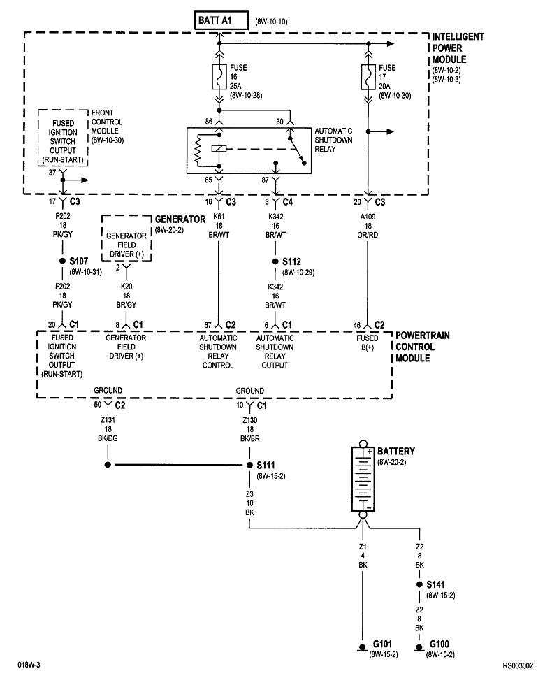
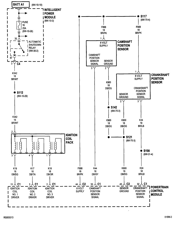
I didn't look closely at these diagrams, but I can add a couple of comments of value. First, it was common on Chrysler Engine Computers to find four ground wires. One was called a "power ground", meaning it was used for high power circuits like ignition coils, injectors, solenoids, and relays. The second was a "sensor ground". Then, for redundancy, there was a second one for each of those, thus, four ground wires in total.

The reason for separate grounds is there is always a little resistance in a wire. When current flows through that resistance, it causes a small voltage to be "dropped" across it. In the high-power ground circuit, that voltage drop could be in the order of a few hundredths of a volt, which is completely meaningless to how well those systems operate. The problem is if that ground wire was to be shared with the sensor grounds, a few hundredths of a volt means a lot to the computer. In the case of the very sensitive MAP sensor, for example, the voltage drop would affect engine performance due to the computer seeing the wrong signal voltage. In addition, as ignition coils and injectors turn off, they create voltage spikes from the collapsing magnetic fields in their coils. Those voltage spikes also show up on the power ground wires. If there was just the one shared ground wire, those voltage fluctuations would again show up in the sensor signals.

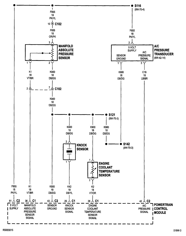
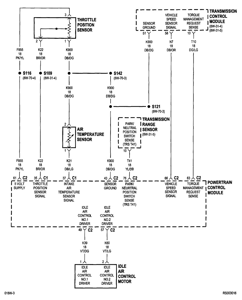
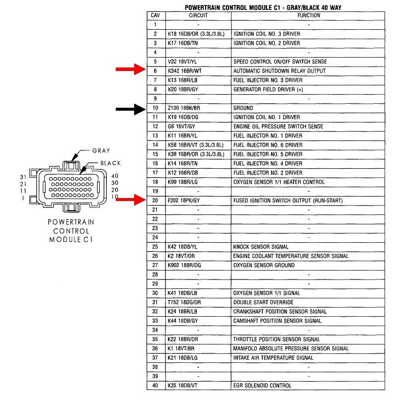
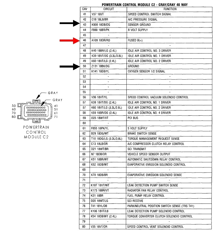
The second problem with testing ground wires is trying to perform a continuity test is pointless. All you need is one tiny strand of wire still intact for the ohm meter to show the entire wire is good. In fact, that would not allow enough current to flow without causing its own severe voltage drop. Think of a garden hose that's 99 percent blocked by a kink. As long as the nozzle is turned off, you would find normal pressure there, but open the nozzle and expect water, (current) to flow, and all it would do is drip on your shoes. Just like with the garden hose, to be accurate, you have to test the circuit while it's in operation. That means instead of the continuity test, measure the voltage drop on each ground wire. To say that in normal terms, measure the voltages on terminals 10, 43, and 50 while the engine is running.

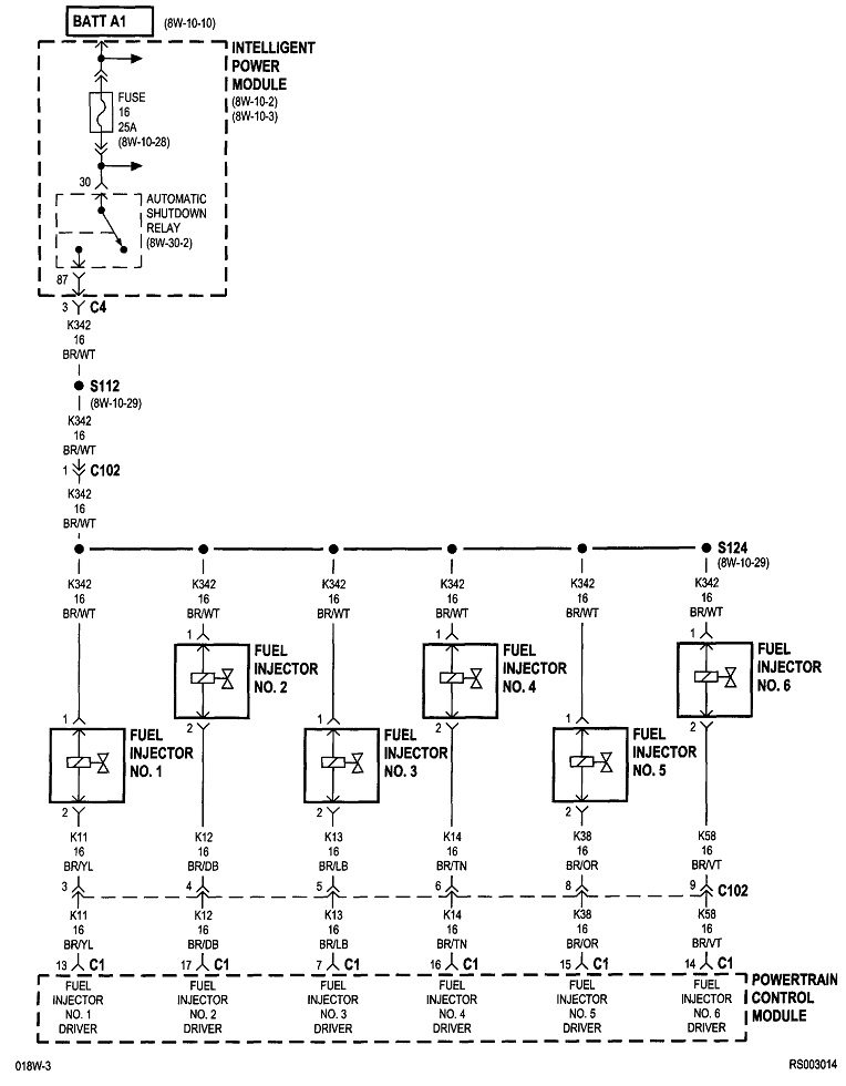
I've never actually done this test except for training purposes, so I don't know what "normal" is, but I can share that you aren't going to find a questionable amount of voltage. If a power ground wire is open, as in corroded off at the terminal, you'll have a no-crank or a crank / no-start condition since the ignition coils and injectors can't fire. You'll find very high voltage on that power ground wire, as in probably 2 volts or more.

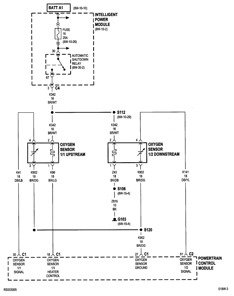
Most sensors are fed with a carefully regulated 5.0 volts. If their ground wires are open, that will put close to that 5.0 volts onto the signal wires. That will set all kinds of "signal voltage high" fault codes related to each of those sensors. When you get that code for just one sensor, suspect a break inside the sensor itself, a spread connector terminal, or a break in the wire from that sensor to where it splices together with the other sensors' ground wires. When you get those fault codes for multiple sensors, that's when to look at the sensor ground wire for the computer.

As a side note, power grounds go through the computer because that's where it turns those circuits on and off. Sensor grounds go through the computer so they can be monitored for proper operation. Because there is that monitoring circuitry in the computer, a small amount of voltage is dropped across it. To see that, go to the ground terminal for the throttle position sensor or the MAP sensor, and you'll find very close to 0.20 volts, not 0.00 volts like you might expect to see.

All of these voltages are part of the training story. In actual practice, we never waste our customers' time, (money), with these tests during the diagnosis. We might perform one or two to verify what we found, but there's too many other variables to make these tests worthwhile. A perfect example is the stray voltage that can be "induced" electromagnetically into your meter's leads. You may even find when your meter is set to its lowest voltage scale, it will show a small voltage just by sitting near the running engine without its leads even touching anything.

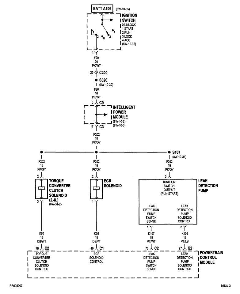
For the computer's 12-volt power wires, I've seen up to four of them. One is on all the time to keep the memory alive. That keeps any stored fault codes in memory and it retains learned values like individual sensor personalities and learned fuel trim data. The second will be a switched power wire that turns the computer on from the ignition switch. I briefly mentioned the automatic shutdown, (ASD) relay previously. The computer turns that on for just one second when the ignition switch is turned to "run", then again anytime it sees engine rotation, (cranking or running). When it's turned on, it sends 12 volts to the ignition coil(s), injectors, alternator field, oxygen sensor heaters, and to the fuel pump or pump relay. One additional place it sends 12 volts is back to the Engine Computer so it can verify that ASD relay did, in fact, turn on. That's the third 12-volt power wire and it is the one that powers the alternator's voltage regulator circuit and is where system voltage is monitored. That regulator is inside the Engine Computer. Chrysler developed the world's first electronic voltage regulator for 1970 models. One of its features was it included temperature compensation to boost battery charging voltage in cold weather. Today, with the regulator built into the computer, it can make fine tuning adjustments for all the variables the computer knows.

There's one more thing I want to point out that is a major source of confusion. That is the terminology used for some of these circuits. The biggest one that comes to mind is terminal # 6 in connector C1. It's listed as, "automatic shutdown relay output". That implies the ASD relay turns on, then its output 12 volts comes out on terminal #6. That's how most of us would read it. In fact, what it means is the ASD relay turns on, then, along with all the places I said it sends 12 volts to, this relay's "output" goes TO terminal # 6. The output of the relay is an input to the computer on terminal # 6. That's what happens when the engineers who design the circuits aren't the same people who write the service manuals.
May 28, 2025 at 12:23 PM
Avatar
CHRYSLER 01
  • MEMBER
  • 68 POSTS
okay, so telling me to check for 12 voltage on a ground wire, like put my test light or voltameter.
May 28, 2025 at 12:39 PM
Avatar
CHRYSLER 01
  • MEMBER
  • 68 POSTS
okay, you said the ASD relay power the alternator voltage regulator.
May 28, 2025 at 12:44 PM
Avatar
CHRYSLER 01
  • MEMBER
  • 68 POSTS
you seem to know your stuff very well.
May 28, 2025 at 12:44 PM
Avatar
CARADIODOC
  • CERTIFIED EXPERT
  • 34,306 POSTS
Test light won't do it. Those need a good 6 to 8 volts before they start to light up. You need a digital voltmeter, ideally with the lowest voltage range of less than 2.0 volts. You're expecting to find just a few hundredths of a volt. Put the meter's negative probe on a clean, rust and paint-free point on the body sheet metal or screw head, and the positive probe right on the computer's terminal by back-probing alongside the wire, through any rubber weather seal. You can go all the way back to the battery too, if you want to, and put the meter's negative probe on the battery's negative post. That will include more connections in the test, but you should still ideally, find close to 0.00 volts on the ground wires.

Remember, if you find any really low voltage with this test, that wire is okay. If you have a wire with a bad ground, say it's corroded off the terminal or the terminal is bolted to a badly rusted area of sheet metal, you're going to find some high voltage that is obviously too high. What I didn't do a good job of saying is you're not going to have to question whether a voltage you find is good or bad. If it's bad, it will be obvious.
May 28, 2025 at 12:50 PM
Avatar
CARADIODOC
  • CERTIFIED EXPERT
  • 34,306 POSTS
"Ok you said the ASD relay power the alternator voltage regulator"

To be clear, the alternator and regulator have nothing to do with the problem you're chasing. I just included them in my story to show all the places you need to have 12 volts at the Engine Computer. Unless I overlooked one, I only saw three 12-volt feeds that you can check.
May 28, 2025 at 12:53 PM
Avatar
CARADIODOC
  • CERTIFIED EXPERT
  • 34,306 POSTS
I'll be back tomorrow to see how you're doing, but expect to see me later in the day or early evening.
May 28, 2025 at 1:00 PM
Avatar
CHRYSLER 01
  • MEMBER
  • 68 POSTS
okay, so send my digital multimeter to lowest setting and measure volts on ground side #10 / #50 / #43.
May 28, 2025 at 1:03 PM
Avatar
CHRYSLER 01
  • MEMBER
  • 68 POSTS
this is the email I got from all computer when I told to send me another PCM....

With these old SBEC Modules it is very important that the ECU makes a solid and secure connection to the harness. At times, it does require some force to get the locking tabs on the connector to lock in place. Please check this, and perhaps having an assistance push the module in while you try to start. If too much force is required but the vehicle does start, that means some of the connector terminals inside the harness have been pushed back and will need to be reset.
May 28, 2025 at 1:23 PM
Avatar
CHRYSLER 01
  • MEMBER
  • 68 POSTS
they sold a program ECM at first the car was cranking, and starting and running 10 seconds now the problem came back no start....
May 28, 2025 at 1:24 PM
Avatar
CARADIODOC
  • CERTIFIED EXPERT
  • 34,306 POSTS
Pushing on the plugs is a common thing to look for, but they're really pretty good as far as connections. I always look for pushed out pins but I've never found one yet. The only bent over terminal I ever ran into is one that I caused through carelessness.

At this point, if the starter cranks okay but the engine doesn't run, you're going to need a scanner to see what the computer is seeing for the crankshaft position sensor and the camshaft position sensor. I described earlier how they should switch from "No" to "Present" or something similar when you start cranking the engine. If one of those doesn't switch to "Present", that is the circuit we need to look at closer.
May 29, 2025 at 8:17 PM
Avatar
CHRYSLER 01
  • MEMBER
  • 68 POSTS
I'm taking a break from this car. I'll let you know when I get back to it.
Jun 24, 2025 at 5:11 PM
Avatar
CARADIODOC
  • CERTIFIED EXPERT
  • 34,306 POSTS
Dandy. I'm here almost every day, usually late afternoon to late evening. I'll wait for your next update.

I do have one more comment while I think of it. This model was known for having a starting problem due to a broken solder connection on the plug on the back of the instrument cluster. I've read about it multiple times here, but I actually ran into it just once, on a relative's van. That was a few years ago, and I can't remember if it was a crank / no-start, or if it caused a no-crank condition. Regardless, it did not cause stalling after the engine was running. Banging on the dash was his solution for a few months until that no longer worked. Once the cluster is removed and disassembled, the broken solder joint was easy to see and resolder. The affected pin was in one of the corners of the plug.
Jun 24, 2025 at 5:24 PM