All gauges stop working ?

2005 FORD FOCUS
90,876 MILES • 4 CYL • 2WD • AUTOMATIC
Avatar
ARLENE SMITH
  • MEMBER
  • 1 POST
i start car and after 15 min. all gauges stop working and when shut off car it starts like a dead batt. but batt. is good
Aug 16, 2010 at 12:20 PM
Advertisement
Avatar
RASMATAZ
  • CERTIFIED EXPERT
  • 75,992 POSTS
Hi Arlene Smith, Welcome to 2carpros and TY for the donation

Double check battery condition and connections to include the alternator if its putting out the correct voltages-if okay start by having the starter relay and ignition switch tested.
Aug 16, 2010 at 5:52 PM
Avatar
L BANES
  • MEMBER
  • 5 POSTS
temperature gauge, speedometer and fuel gauge intermittent work then do not work. i found taped joint underneath car when moving it got a response fuel gauge worked all was well it happened again. i then removed the tap from the joint and wires just fell apart. i had two black wires going back somewhere and a black and green/yellow going towards front of vehicle and into wiring, i do not know if there the right way round but took a chance still nothing worked. i then reversed them still no joy. all fuses test okay, every thing else works. thanking you, Mr. L Banes.
Nov 27, 2020 at 4:47 PM (Merged)
Advertisement
Avatar
STRAILER
  • CERTIFIED EXPERT
  • 53,854 POSTS
Hello,

Yes, I have this car so lets fix you up. Can you take a picture for what you are talking about so I can see whats going on? Upload it here in your response.

Please get back to us.

Cheers, Ken
Nov 27, 2020 at 4:47 PM (Merged)
Avatar
L BANES
  • MEMBER
  • 5 POSTS
Hi Ken.

Got a old connector from breakers it fitted to engine near off side front headlight. do not know what it works though.
Nov 27, 2020 at 4:47 PM (Merged)
Avatar
STRAILER
  • CERTIFIED EXPERT
  • 53,854 POSTS
So the wires you are holding are from under the hood? Can I get a picture of the area and color of the wiring please?
Nov 27, 2020 at 4:47 PM (Merged)
Avatar
L BANES
  • MEMBER
  • 5 POSTS
Hi Ken

Here is picture of brake the white shown. When con is fitted there are two black wires to the left and green and yellow to right the left slant of bracket are the two black wires. Sorry to be so jumbled the pulley is the bottom of engine.
Nov 27, 2020 at 4:47 PM (Merged)
Avatar
STRAILER
  • CERTIFIED EXPERT
  • 53,854 POSTS
This look like a compressor wire, is it this wire the one you move to get the cluster to work or is this other problem?
Nov 27, 2020 at 4:47 PM (Merged)
Avatar
2CP-ARCHIVES
  • MEMBER
  • 4,540 POSTS
gauges on instrument panel quit working?
Nov 27, 2020 at 4:47 PM (Merged)
Avatar
L BANES
  • MEMBER
  • 5 POSTS
Yes they come to life then but i have not connected them because i do not know which way round. if i get it wrong what is the worst that could happen?
Nov 27, 2020 at 4:47 PM (Merged)
Avatar
ASEMASTER6371
  • CERTIFIED EXPERT
  • 52,796 POSTS
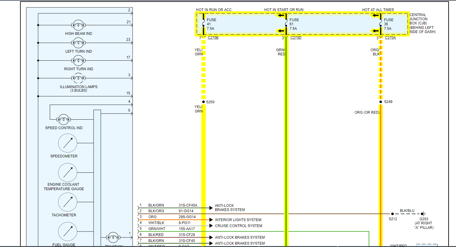
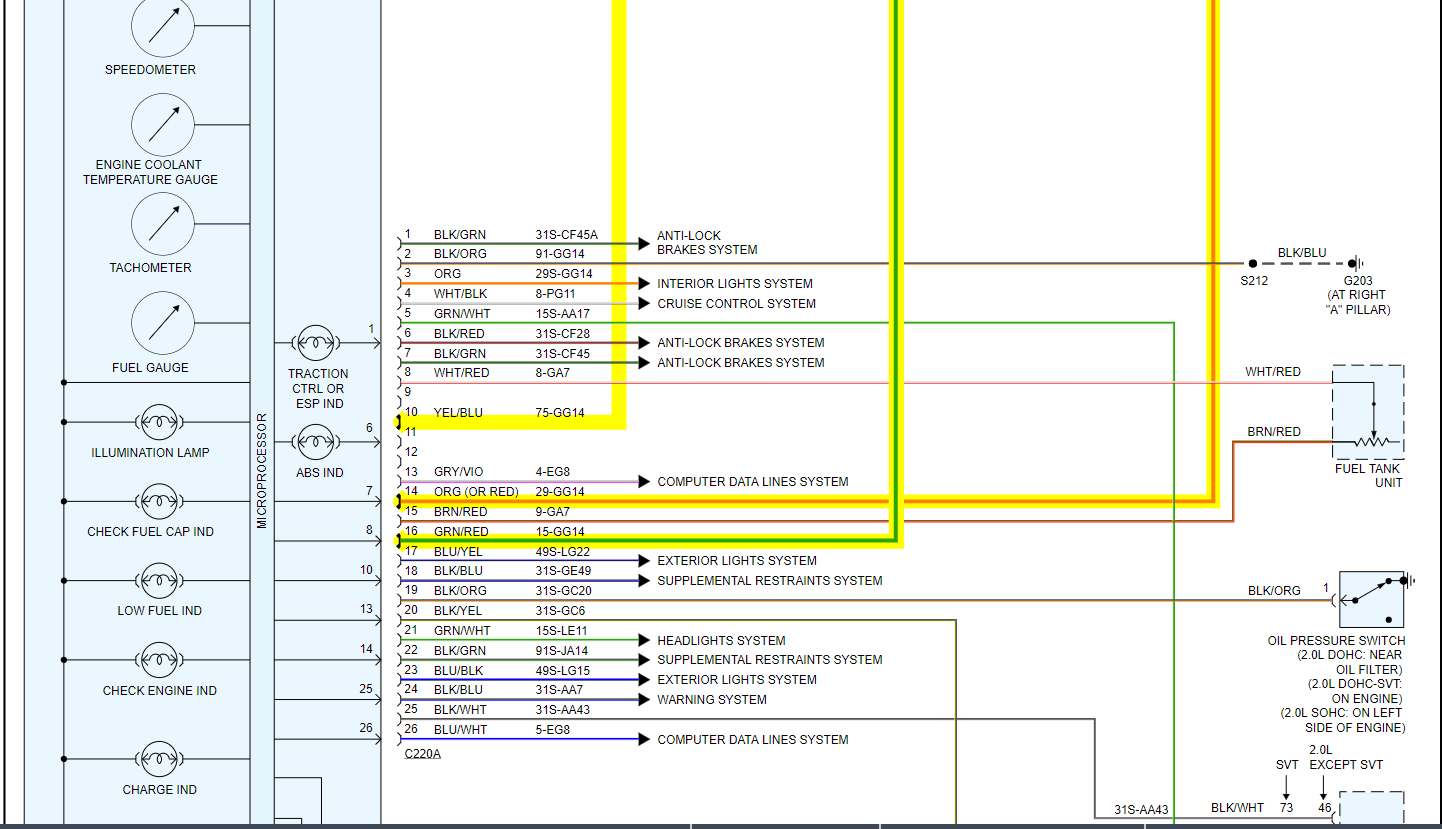
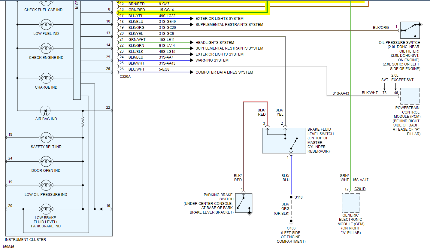
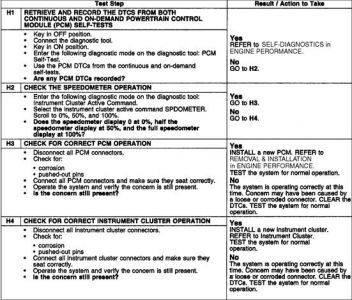
I attached a wiring diagram for you to check. You need to test the fuses listed for power on both sides as they provide power for the cluster to work.

https://www.2carpros.com/articles/how-to-check-a-car-fuse

https://www.2carpros.com/articles/how-to-check-wiring

If you have these powers then the cluster has failed and needs to be replaced. The instructions are below as well.

Roy

INSTRUMENT CLUSTER

REMOVAL

NOTE: If a new instrument cluster is being installed connect WDS. Upload the instrument cluster configuration information using the programmable modules installation routine prior to commencing the removal of the instrument cluster.


imageOpen In New TabZoom/Print


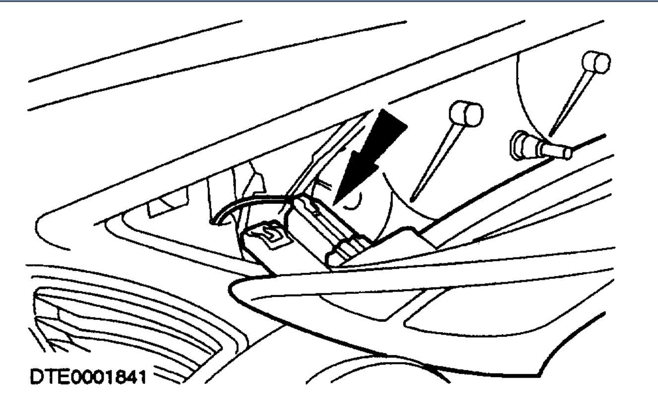
1. Detach the instrument cluster bezel. (Steering wheel removed for clarity).


imageOpen In New TabZoom/Print


2. Remove the instrument cluster bezel.
Disconnect the luggage compartment release switch electrical connector.


imageOpen In New TabZoom/Print


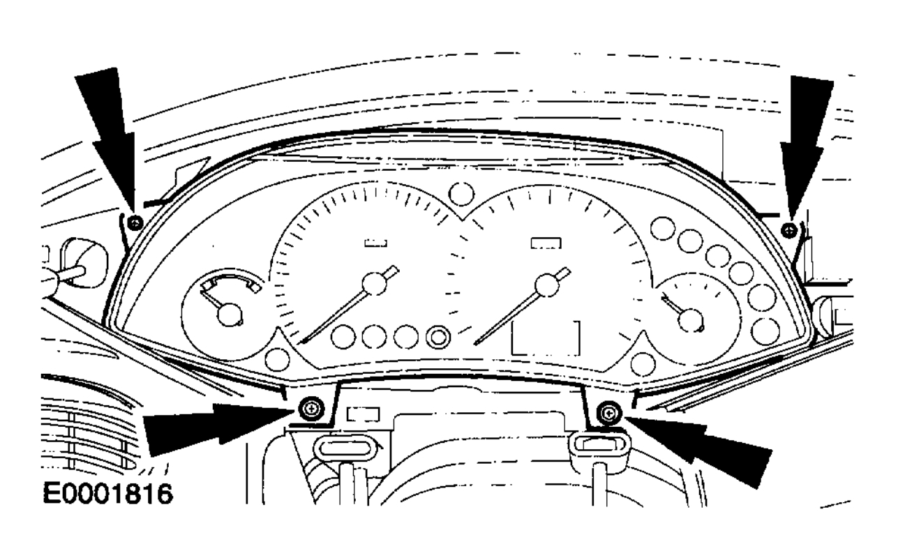
3. Detach the instrument cluster.


imageOpen In New TabZoom/Print


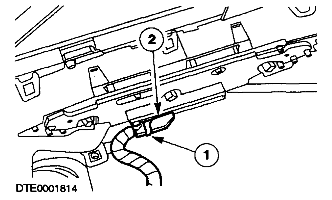
4. CAUTION: The instrument cluster must be kept upright to avoid silicone liquid leaking from the gauges.

Remove the instrument cluster.
1 Release the locking tang.
2 Disconnect the instrument cluster electrical connector.

INSTALLATION

1. NOTE: If a new instrument cluster is being installed connect WDS. Download the instrument cluster configuration information using the programmable modules installation routine after the installation of the instrument cluster.

To install, reverse the removal procedure.
Nov 27, 2020 at 4:47 PM (Merged)
Avatar
STRAILER
  • CERTIFIED EXPERT
  • 53,854 POSTS
You will blow a fuse is all, if they are both black it should not matter.
Nov 27, 2020 at 4:47 PM (Merged)
Avatar
L BANES
  • MEMBER
  • 5 POSTS
Okay.
Will give it ago later and will let you know the outcome.
Nov 27, 2020 at 4:47 PM (Merged)
Avatar
L BANES
  • MEMBER
  • 5 POSTS
Hi ken.

Good news, made connection gauges up and running been for long drive. Everything seems okay.

Thank you ever so much and take care.
Les.
Nov 27, 2020 at 4:47 PM (Merged)
Avatar
STRAILER
  • CERTIFIED EXPERT
  • 53,854 POSTS
Use 2CarPros anytime, we are here to help. Please tell a friend.

Cheers, Ken
Nov 27, 2020 at 4:47 PM (Merged)
Avatar
PSTYSOCKS
  • MEMBER
  • 1 POST
Electrical problem
2003 Ford Focus 4 cyl Two Wheel Drive Manual 47.989 miles

hi i have a 1.4 5 door focus on a 03 plate and when im driving my speedo and rev counter also temp gage and mile counter will not work i have have someone out to test for fault and saying no fult found this happens only sometimes but yesyerday it was all the time when i was driving also when the car is just sat ticking over
Nov 27, 2020 at 4:47 PM (Merged)
Avatar
DAVE H
  • CERTIFIED EXPERT
  • 13,384 POSTS
Hello .. thanks for the donation ..much appreciated Have the car plugged into a good diagnostic scanner to check for fault codes stored on the BCM (body control module) Principles of Operation NOTE:Upon installation, a new instrument cluster must be reconfigured. For additional information, refer to MODULE CONFIGURATION . The instrument cluster is a hybrid electronic cluster (HEC) with two basic configurations, the base cluster and the optional instrument cluster. In addition to the two basic configurations, the SVT uses a modified optional cluster in combination with a separate oil pressure and oil temperature cluster. The base instrument cluster, optional instrument cluster and the oil pressure and oil temperature cluster receive and output information utilizing both hardwired circuitry and the standard corporate protocol (SCP) or the controller area network (CAN) communication network (2.3L only). An additional feature of the SVT instrument cluster and oil pressure and oil temperature cluster configuration is the use of an electro-luminescent backlighting strategy. The electro-luminescent backlighting utilizes switched DC to high AC voltage circuitry. The oil pressure and oil temperature cluster converts 12V DC into AC voltage that is variable up to 180V AC through the dimmer switch control. CAUTION:The SVT instrument cluster utilizes high AC voltage for the electro-luminescent backlighting system in both the instrument cluster and oil pressure and oil temperature cluster. Care must be exercised when making measurements to the instrument cluster circuits. It is very important to understand: where the input originates from. all the information necessary in order for a feature to operate. which module(s) receive(s) the input or command message. does the module which received the input control the output of the feature, or does it output a message over the SCP or CAN network to another module? which module controls the output of the feature. The instrument cluster carries out a display prove-out to verify that the warning/indicator miniature bulbs for monitored systems are functioning correctly. When the ignition switch is placed in the ON position with the engine off, the following warning indicators will prove out: check transmission indicator malfunction indicator lamp (MIL) indicator oil pressure indicator safety belt warning indicator door ajar warning indicator The following indicators are also displayed during prove-out but are not controlled by the instrument cluster: anti-lock brake system (ABS) warning indicator O/D OFF indicator air bag warning indicator brake warning indicator charging system warning indicator shift up indicator low fuel warning indicator traction control indicator CHECK FUEL CAP indicator speed control indicator Tachometer Engine speed data is transmitted to the instrument cluster from the powertrain control module (PCM) over the SCP or CAN communication network. Speedometer The instrument cluster receives the vehicle speed signal from the PCM over the SCP or CAN communication network and displays it on the speedometer gauge. If the instrument cluster receives no vehicle speed signal the speedometer defaults to 0.0 km/h (0.0 mph). Fuel Gauge The instrument cluster receives the fuel level information from the fuel sender unit (part of the fuel pump module). This is a variable resistor which varies the ground supply to the gauge. When the fuel level is low, the resistance is low, when the fuel level is high the resistance is high. If an invalid input signal is received, the fuel gauge will then default to below the empty position. The fuel level input signal is heavily damped to allow for movement of fuel in the tank when the ignition switch is in the ON position. Temperature Gauge Engine coolant temperature information is received by the instrument cluster from the PCM over the SCP or CAN communication network. If the engine coolant temperature information is missing or invalid, the temperature gauge will indicate below the cold (C) position. Odometer/Trip Odometer The odometer and trip odometer are displayed in the integrated circuit LCD display. The instrument cluster records the total mileage of the vehicle, using information received from the PCM and electronically displays this information in the LCD. If this information is not received, the LCD will display all dashes.


https://www.2carpros.com/forum/automotive_pictures/266999_focus_4.jpg

Nov 27, 2020 at 4:47 PM (Merged)
Avatar
TYLER MEGONIGLE
  • MEMBER
  • 2 POSTS
Having same issues in my 2004 Roush zx3 and everything else works except all guages so RPM speed gas and engine temperature also the display docent work I've tried many thing but everything is different in this car then a regular zx3. anyone have any clue how to fix it? they where working fine then they turn off then they will turn back on at a later time.
May 3, 2021 at 12:01 PM
Avatar
JACOBANDNICKOLAS
  • CERTIFIED EXPERT
  • 110,175 POSTS
Hi,

I need you to have you start a new thread. Your vehicle is different from the original vehicle posted. We are trying to keep the threads specific to one vehicle/repair. That way, it is helpful to others.

Simply copy and paste your question. Here is the link to start a new thread:

https://www.2carpros.com/questions/new

Take care,

Joe
May 5, 2021 at 8:26 PM