1994 Ford F250 ecm or eec problems

1994 FORD F-250
198,000 MILES • V8 • 4WD • MANUAL
Avatar
OLEFOGY
  • MEMBER
  • 19 POSTS
Hi, I have a '94 f-250 with a 7.3l powerstroke diesel. The truck had been hard to start ( glow plug lite comes on and goes of after a few seconds) requiring long cranks before it would fire up. Once it firede up it would run down the road with no problems. After awhile of it starting like this, it seemed every so often that it would have a miss. If you then stopped, turned the truck off and started it again it would run smooth with no miss. It ran this way for about 3 weeks when one morning I get in and start it (long cranking then started and ran fine) and get about a mile down the road and the truck steadily lost power and died, coming to a rolling stop. I try to start it. cranks and cranks and will not fire.
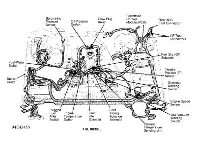
I was able to get a shop to come to my house and put a handheld diagnostic reader on to try and find a fault code. The technician said that his reader used the power coming thru the ECM to power itself up, but he could not get his reader to come on. He said that most likly the ECM had gone bad.
Before I had them come out, I fully charged both batterries and cleaned ALL contact points both positive and negative. Everything electrical still works on the truck, it just wont fire and run.
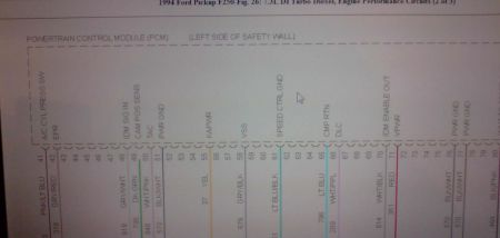
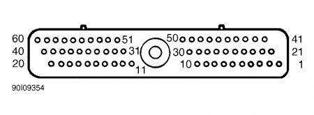
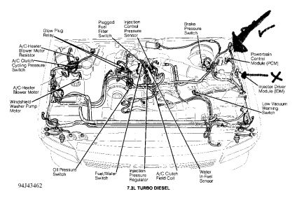
I have heard of a EEC module or relay that is suppossed to provide power for theECM. Do you have any idea on what my problem could be? I am pretty sharp on gasoline engines, but this is my first diesel ( and a powerstroke at that, wich I am told is different than other diesels) and I am lost.
Dec 16, 2008 at 7:33 PM
Advertisement
Avatar
DAVE H
  • CERTIFIED EXPERT
  • 13,384 POSTS
could you supply the 8th character of IN # to verify which engine you have ? have you checked if your getting fuel ?

IDENTIFICATION
NOTE:The eighth character of the Vehicle Identification Number (VIN) identifies the engine. The VIN is stamped on a metal tab attached to top left end of instrument panel and is visible through windshield. VIN is also located on Vehicle Safety Compliance Certification Label on left door or left door post pillar.
Dec 16, 2008 at 8:18 PM
Avatar
OLEFOGY
  • MEMBER
  • 19 POSTS
Ok, the 8th character is F.
My step dad has looked at the truck and he says he believes it is getting fuel but he was unsure as he has only had experience in diesel tractors and has never messed with a powerstroke. There is a shrader valve on the side of the fuel filter housing and fuel seems to come out with pressure when you push in on the valve ( I am guessing that this where you would attach somthing to measure the actual pressure).
What is the approriate way to test for fuel?
Dec 16, 2008 at 9:14 PM
Advertisement
Avatar
DAVE H
  • CERTIFIED EXPERT
  • 13,384 POSTS
check if there is fuel in fuel filter .. ? is the CEL/MIL on (check engine light) if yes we can try to retrieve codes using MIL or Voltmeter ?? RETRIEVING CODES DTCs are retrieved from EEC-IV system through Data Link Connector (DLC). Various methods and test equipment may be used to access these DTCs: Analog Volt-Ohmmeter (VOM). Scan tool. In-Dash Malfunction Indicator Light (MIL)/CHECK ENGINE light. DATA LINK CONNECTOR (DLC) LOCATIONS ApplicationLocation PickupLeft Rear Of Engine Compartment, On Bracket READING CODES KOEO & KOER SELF-TEST DTCs All DTCs are 3-digit numbers. PCM outputs DTCs one digit at a time. These DTCs indicate current faults in system and should be serviced in order of appearance. Go to DIAGNOSTIC TROUBLE CODE IDENTIFICATION to find correct PINPOINT TESTS. DTCs are shown as voltage pulses. If using MIL/CHECK ENGINE light, DTCs are displayed as light pulses. If using Volt-Ohmmeter (VOM), DTCs are displayed as needle sweeps. See Fig. 1 . Pay careful attention to length of pauses in order to read DTCs correctly. A 1/2-second pause occurs between number of sweeps in a digit and a 2-second pause occurs between digits in a DTC. A 4-second pause occurs between each DTC. KOEO DTCs are separated from Continuous Memory Codes by a 6-second delay, a single 1/2-second sweep (Separator) and another 6-second delay. Record DTCs in order received. Scan tool, if used, will count pulses and display them as a digital code. Star Series Tester will add a zero (0) to single-digit Separator Code (10) and Dynamic Response Code (10). Dynamic Response Code is displayed in KOER SELF-TEST. See Fig. 1 . Separator Code Single 1/2-second separator pulse is issued 6-9 seconds after last KOEO DTC. Continuous Memory Codes (soft faults) are then displayed 6-9 seconds after 1/2-second separator code. Some digital test equipment may display separator code as "10" instead of "1". Pass Codes Code 111 indicates system passes that portion of test. If Code 111 is not retrieved in KOEO SELF-TEST, DTCs retrieved during KOER SELF-TEST may not be valid. DTC 111-1-111, output during KOEO SELF-TEST, indicates no KOEO DTC or Continuous Memory Code was recorded. Continuous Memory DTCs Continuous Memory DTCs are displayed after separator pulse code in KOEO SELF-TEST. These DTCs result from information stored by PCM during continuous self-test monitoring. These DTCs indicate faults recorded within last 40 engine starts (80 engine starts on some models). Fault may or may not be currently present. Go to DIAGNOSTIC TROUBLE CODE IDENTIFICATION . Use these DTCs for diagnosis only when KOEO SELF-TEST and KOER SELF-TEST result in DTC 111. Fast Codes At start of KOEO SELF-TEST and after Wide Open Throttle (WOT) request in KOER SELF-TEST, PCM outputs short bursts of information, known as FAST CODES, which were used by manufacturer during assembly. With most equipment, these code bursts are not visible; an entire DTC sequence lasts less than 1/2 second. If this fluctuation is visible on test equipment, ignore it.


https://www.2carpros.com/forum/automotive_pictures/266999_dtc_2.jpg

Dec 16, 2008 at 9:55 PM
Avatar
OLEFOGY
  • MEMBER
  • 19 POSTS
I went and turned on the key and I am not showing a check engine lite. I do not recall it ever coming on at all in the time that I have owned the truck.
It is to dark and cold here right now (about 10pm)to get under the hood so I will get back to you tommorow ( before noon, my time) when I am able to do somthing. Thank you for taking the time to help me.
Dec 16, 2008 at 10:28 PM
Avatar
DAVE H
  • CERTIFIED EXPERT
  • 13,384 POSTS
it is possible when you disconnected battery to clean the terminals any/all the fault codes were deleted for the PCM's memory ... but you should still see the MIL light up for 3/5 seconds on initial turn of key on ?? do you see it coming on ??
Dec 17, 2008 at 10:15 AM
Avatar
OLEFOGY
  • MEMBER
  • 19 POSTS
No there is no MIL lighting up when I turn on the truck. I have tried turning the truck on on 3 separate occassions and there is no MIL lighting up at any time.
I cannot get the top off of the fuel filter off (it is pretty cold here and that could be why, but I changed the fuel filter about 6 months ago and I did put it on pretty tight.) but there is a drain lever on the front left side of the filter housing. I turned it and fuel ran out of the drain and on the ground, so i'm guessing there must be fuel in the filter. I just now plugged in the block heater, so in awhile I should be able to safetly try to turn it over if you need me to.
Dec 17, 2008 at 12:42 PM
Avatar
DAVE H
  • CERTIFIED EXPERT
  • 13,384 POSTS
we don't seem to have power going to the PCM check fuse "I" in underhood fuse/relay box ..check all the fuses while you are there ? it must be getting fuel if the drain is letting fuel out ?? you can also try cranking it over ???


https://www.2carpros.com/forum/automotive_pictures/266999_fuse_16.jpg

Dec 17, 2008 at 1:04 PM
Avatar
OLEFOGY
  • MEMBER
  • 19 POSTS
Ok, I both visually inspected and used a test lite. I do have power at fuse "I", but no power at fuses E, F,G,or U. I have not tried to crank it yet.
Dec 17, 2008 at 2:49 PM
Avatar
OLEFOGY
  • MEMBER
  • 19 POSTS
Also, after the truck had stalled and then not started again I had checked this fuse panel and saw that fuse "T" was burned out so I replaced it but it had no noticable effect on making the truck start.
Dec 17, 2008 at 2:55 PM
Avatar
DAVE H
  • CERTIFIED EXPERT
  • 13,384 POSTS
could you check fuse # 13 in interior fuse panel ... fuse T E F G are all related to the trailer plug .. E is also for back up lamps ?? fuse U is for PCM power relay coil ..check fuse # 13 inside fuse panel
Dec 17, 2008 at 3:15 PM
Avatar
OLEFOGY
  • MEMBER
  • 19 POSTS
Ok sorry to leave you hanging. Fuse 13, inside panel, is good and test light shows power.
Dec 17, 2008 at 5:55 PM
Avatar
DAVE H
  • CERTIFIED EXPERT
  • 13,384 POSTS
have you got power to fuse "U" with ignition on ...?? we also need to check we are getting power to pin 71 and pin 97 both red wires on PCM wiring connector (red wire) on multiconector to PCM on left side of firewall in engine compartment ?
Dec 17, 2008 at 6:35 PM
Avatar
DAVE H
  • CERTIFIED EXPERT
  • 13,384 POSTS
also check pin # 14 dark green/light blue wire this should ahve 12 volt's also at key on ??
Dec 17, 2008 at 6:42 PM
Avatar
OLEFOGY
  • MEMBER
  • 19 POSTS
There is power at fuse "U" when ignition is on.
Is the PCM located inside the drivers front fender? If so I cannot locate a red wire. It seems as though there are two pinks. Do you have a diagram of the wires as they come into the PCM?
Dec 17, 2008 at 7:06 PM
Avatar
DAVE H
  • CERTIFIED EXPERT
  • 13,384 POSTS
you could also check pin #55 yelllow wire ..


https://www.2carpros.com/forum/automotive_pictures/266999_ppcm_1.jpg


https://www.2carpros.com/forum/automotive_pictures/266999_pcmwire_1.jpg

Dec 17, 2008 at 7:28 PM
Avatar
DAVE H
  • CERTIFIED EXPERT
  • 13,384 POSTS
the connector terminal unplugged looks like this ??


https://www.2carpros.com/forum/automotive_pictures/266999_con1_1.jpg

Dec 17, 2008 at 7:37 PM
Avatar
OLEFOGY
  • MEMBER
  • 19 POSTS
Does the the PCM have somthing to do with the injectors because the thing I am looking at says red striped wires carry 115v. If this is the case, the only color that matched the ones you gave me was yellow.
Dec 17, 2008 at 9:09 PM
Avatar
DAVE H
  • CERTIFIED EXPERT
  • 13,384 POSTS
you are looking at the Injector Driver Module (IDM) 7.3L Turbo Diesel...In left side of engine bay. the one with the X in this picture ... you want the one above it with the "tick" large arrow it has a large wiring loom with 60 wires going to it ?? and a big plug as described in my last picture ?


https://www.2carpros.com/forum/automotive_pictures/266999_pcm_1.jpg

Dec 17, 2008 at 9:44 PM
Avatar
OLEFOGY
  • MEMBER
  • 19 POSTS
Oops, my bad for not saying turbo diesel in my initial disciption. Sorry for the confusion.
Yeah that second picture is was more helpful. Well, it is getting to be about the same time as it was last night when I quit so I am going to stop messing with it for tonight. I will test those wires in the morning and get back with you then. One more question, does the harness need to be bolted to the connector( firewall) in order for me to test the wires or can I take it loose and test light the pins where they come out of the end of the harness?
Dec 17, 2008 at 10:07 PM
Avatar
DAVE H
  • CERTIFIED EXPERT
  • 13,384 POSTS
take it out and and test the pins .. you will have to have the ignition ON ... o.k. speak tommorrow
Dec 17, 2008 at 10:11 PM
Avatar
OLEFOGY
  • MEMBER
  • 19 POSTS
Ok, I am lost. The picture you sent of the connector has 3 rows of 10 on each side for a total of 60. My connector has 4 rows of 13 on each side for a total of 104.
I have no pin 14 on my harness. Pin 55 has constant 12v when key is off or on. Pin 71 has 12v with ignition on and pin 97 has 12v with ignition on. I am looking in the right place?
Dec 18, 2008 at 10:02 AM
Avatar
DAVE H
  • CERTIFIED EXPERT
  • 13,384 POSTS
ok .. forget pin14 that was my mistake ? your correct 104 pins the diagram was just to show roughly what it looked like ..i don't have a diagram of your plug ..should have said so, sorry ? so we are getting power to the PCM correctly .. we need to check why the light is not coming on ?? do you see the DLC data link connector where the tech plugged in his scanner ?? plug back in the PCM connector and check which wires are/are not getting power at DLC
Dec 18, 2008 at 10:55 AM
Avatar
OLEFOGY
  • MEMBER
  • 19 POSTS
There is a plug marked EEC TEST and that is the one I believe he used. There are 4 wires; 1 yellow w/purple strip, 2 red w/green stripe (both reds go to the same spade connector), and 1 gray w/ red stripe. None have power with key off and only the 2 reds have power when key is on.
Dec 18, 2008 at 11:15 AM
Avatar
DAVE H
  • CERTIFIED EXPERT
  • 13,384 POSTS
the gray/w/red is the signal return from PCM this will give us the codes ?? the red w/green are power to DLC and power to MIL so i'm guessin the MIL bulb has blown because the wire has power going through it ?? i'm showing a white/purple wire for the signal in to PCM from DLC/scan tool .... so theoretically the PCM is working and the DLC has power to it so your tech should have got a link .. it could be that he didn't have the correct scanner Diesel cars are different untill 2004 when they became intergrated into the generic system ... do you think you could read the codes in the step's i posted earlier using a voltmeter ??
Dec 18, 2008 at 11:53 AM
Avatar
OLEFOGY
  • MEMBER
  • 19 POSTS
Yes, I belive I could read the codes. i will need to go and get a cheap analog voltmeter. The only one I have is digital. I can not see the diagram very well to make out the smaller writing on this thread. Can you send a blown-up version of it to my e-mail?
Dec 18, 2008 at 12:02 PM
Avatar
DAVE H
  • CERTIFIED EXPERT
  • 13,384 POSTS
no problem I have sent you a private message for the Email address
Dec 18, 2008 at 12:09 PM
Avatar
OLEFOGY
  • MEMBER
  • 19 POSTS
Hey I never recieved an e-mail. I don't think my PM's have been going thru.
Dec 18, 2008 at 9:04 PM
Avatar
DAVE H
  • CERTIFIED EXPERT
  • 13,384 POSTS
I never recieved any PM, sorry i had to go out last night ? let me know if you can see this any better ?


https://www.2carpros.com/forum/automotive_pictures/266999_dtc2_2.jpg


https://www.2carpros.com/forum/automotive_pictures/266999_dtc3_1.jpg

Dec 19, 2008 at 3:30 AM
Avatar
OLEFOGY
  • MEMBER
  • 19 POSTS
Hey thanks. I can read see those alot better. I will work on the truck later today and let you know what I find out.
Dec 19, 2008 at 8:21 AM
Avatar
OLEFOGY
  • MEMBER
  • 19 POSTS
Ok, I got my analog meter, what do I do to get this thing to give me the codes?
Dec 20, 2008 at 6:11 PM
Avatar
OLEFOGY
  • MEMBER
  • 19 POSTS
You still out there?
Dec 23, 2008 at 10:05 AM
Avatar
DAVE H
  • CERTIFIED EXPERT
  • 13,384 POSTS
I seem to be having trouble getting my emails ... i'm notified by email when people respond but i seem to be getting them late for some reason ... sorry i'm looking into it ... also I cannot find the hook up diagram for your STI connector .. i'm going to ask another mederator to assist .. we be lettting you know soon
Dec 23, 2008 at 3:14 PM
Avatar
OLEFOGY
  • MEMBER
  • 19 POSTS
Hey, you got anything for me yet?
Dec 29, 2008 at 11:55 AM
Avatar
DAVE H
  • CERTIFIED EXPERT
  • 13,384 POSTS
sorry about the time frame with reply .. I have been waiting on a reply from a colleague with computer problems and the holidays etc. .. I still haven't got the start off sequence for flash/VOM coding the PCM .. so in the meantime lets go back to basics with a few check's ...could you crack open an injector pipe and turn over the engine a couple of times to make sure we are getting fuel into the chambers ? if we are getting no fuel try putting a wire (jumper)between the 2 terminals on the oil pressure switch wires (loop the terminals together to simulate a connection) on the wires to switch not the actual switch ....and try and start the vehicle again with injector pipe back on and tight .. let me know
Dec 31, 2008 at 5:53 AM
Avatar
OLEFOGY
  • MEMBER
  • 19 POSTS
Hey. It has been a couple months since I have been on here and I was wondering if I could still get help with a few questions.
I have since takin the truck to a mechanic friend of mine and although he has not gotten it to start, he has answered a few questions. First off is that the truck does have power to all systems and the ecm is in perfect working order. The problem is no fuel. No matter which tank you select there is still no fuel coming to the engine. this seems like an easy fix until you consider that there are two seperate pumps and other regulators and relays. The problem is, is that we cannot find a code reader for a '94 f-250 7.3l powrestroke. Even the Snap-on rep said that they don't have one that he knows off.
So my question is, can you give me some direction to go in, like maybe common problems associated with this model year and problems relating to fuel?
Jun 21, 2009 at 12:22 AM
Avatar
DAVE H
  • CERTIFIED EXPERT
  • 13,384 POSTS
Hey. I suspect the fuel pump is the fault if you are not getting fuel to the filter assembly !! The pump is a mechanical pump using a camshaft lobe and a diaphragm to pump fuel ..the PCM controls fuel injection and glow plug control !! The fuel system used on 7.3L Direct Injection (DI) turbo diesel engine is: Controlled by Powertrain Control Module (PCM). Comprised of a two-phase fuel pump. Uses a one-piece fuel filter, water separator and fuel heater assembly. Fuel is drawn from fuel tank by fuel pump, then under low pressure is circulated through fuel filter and back to fuel pump to be circulated under high pressure to cylinder head fuel galleries. From there, fuel is delivered to combustion chambers through electronically controlled/hydraulically actuated fuel injectors. A vacuum switch mounted on fuel filter housing monitors vacuum in fuel filter. When vacuum exceeds 7 psi, vacuum switch closes, causing PLUGGED FUEL FILTER indicator on instrument cluster to illuminate. The cylinder heads are specially designed to incorporate electronically controlled/hydraulically activated fuel injectors located near center of combustion chamber.


https://www.2carpros.com/forum/automotive_pictures/266999_2502_2.jpg

Fuel Pump The 2-phase type fuel pump is comprised of the following: Fuel inlet (from fuel tank). Inlet check valve. Diaphragm, diaphragm rod and diaphragm spring. Piston and piston spring. Low-pressure inlet (from fuel filter). Low-pressure inlet check valve. "O" ring, oil seal and fuel seal. Camshaft actuated tappet. High-pressure outlet check valve. High-pressure outlet (to cylinder head). Low-pressure outlet check valve. Low-pressure outlet (to fuel filter). Fuel is drawn from fuel tank by diaphragm section of fuel pump. The fuel pump circulates fuel at about 3-10 psi (21-69 kPa), first through fuel filter and then back to second stage of fuel pump. During second stage, piston-actuated section of fuel pump supplies fuel at a pressure of about 40 psi (275 kPa) into cylinder head fuel galleries. hope this helps ... let me know


https://www.2carpros.com/forum/automotive_pictures/266999_AAA2_795.png

Jun 22, 2009 at 5:00 AM