Engine cranks but will not start

2006 CHEVROLET MONTE CARLO
200,000 MILES • 5.3L • V8 • 2WD • AUTOMATIC
Avatar
RONALD DEVOLD
  • MEMBER
  • 134 POSTS
The car listed above is an SS model.
The engine will crank but will not start. Fuel pressure reads 56PSI.
Feb 7, 2022 at 11:56 AM
Advertisement
Avatar
AL514
  • CERTIFIED EXPERT
  • 5,462 POSTS
Hello, have you checked to see if you have spark? Does the Check Engine Light come on while cranking?

https://www.2carpros.com/articles/how-to-test-an-ignition-system

https://www.2carpros.com/articles/how-to-test-a-fuel-injector
Feb 7, 2022 at 12:21 PM
Avatar
RONALD DEVOLD
  • MEMBER
  • 134 POSTS
i was going to check for spark, but now it will not crank.
Feb 7, 2022 at 12:38 PM
Advertisement
Avatar
AL514
  • CERTIFIED EXPERT
  • 5,462 POSTS
oh okay, do you need the starting circuit diagrams? The starter circuit goes from the Ignition Switch to the Body Control Module to the Engine Control module to the Starter Relay. not sure why they need to make a starter circuit so complicated, either a BCM or ECM failure will cause a not start, or even just a bad ground on either of those modules will cause the same thing...
Feb 7, 2022 at 12:43 PM
Avatar
RONALD DEVOLD
  • MEMBER
  • 134 POSTS
Also, P0315 DTC (Crankshaft Position System Variation Not Learned).
U0100 (Lost Communication with ECM).
Feb 7, 2022 at 12:55 PM
Avatar
AL514
  • CERTIFIED EXPERT
  • 5,462 POSTS
Ahh, I see. well, I would go after the No Communication code first. If the ECM is not powering up or part of it has failed it won't be able to read a Crank sensor signal. I was surprised you were able to even get that code out of it. Were you able to see the ECM in your scan tool? Can you read any live data from the ECM.?

Here's all the fuses i would check first. The Body Control module controls all the starting commands in this vehicle. So that's going to be the first thing to check, also because it powers up the ECM. On the second diagram the ground connection G111 circled in blue needs to be checked also.
Feb 7, 2022 at 1:00 PM
Avatar
RONALD DEVOLD
  • MEMBER
  • 134 POSTS
Okay. so, now i can crank it. i put a spark tester on the #1 plug and coil and plug. tester does not light up.
Feb 9, 2022 at 3:30 PM
Avatar
AL514
  • CERTIFIED EXPERT
  • 5,462 POSTS
Did you do anything to get the starter to crank? If not and it started cranking without repairing anything, I would check the ECM main connector, The ECM is inside the Air Filter box. You should check that there isnt any corrosion on the ECM connector or if any rodents got into the box and chewed on the wires. Since you had a no crank condition to begin with, I think this issue might be more than just a crankshaft position sensor fault or camshaft sensor.
The 1st diagram below is the 12volt feed to each Ignition Coil.
The 2nd is the Power Feed for the Ignition Coils and the Fuel Injectors.
And the 3rd diagram is the control wire for each ignition coil. These are what they call "Smart Ignition Coils". They have an ignition module inside each coil. The highlighted control wires are usually a 0-5 volt square wave that controls the coil on and off time. But check the engine computer wiring harness in the air filter box and make sure theres no harness damage. And does the Check Engine light come on while cranking the vehicle? It should, if it doesnt that means the ECM is not being powered up.

https://www.2carpros.com/articles/how-a-car-computer-works-pcm-ecm-bcm
Feb 9, 2022 at 7:11 PM
Avatar
RONALD DEVOLD
  • MEMBER
  • 134 POSTS
I swapped out the main fuse box assembly. the one under the hood by battery.
Feb 10, 2022 at 7:50 AM
Avatar
AL514
  • CERTIFIED EXPERT
  • 5,462 POSTS
Does the check engine light come on while cranking the vehicle over?
Feb 10, 2022 at 11:29 AM
Avatar
RONALD DEVOLD
  • MEMBER
  • 134 POSTS
yes.
Feb 11, 2022 at 8:33 AM
Avatar
AL514
  • CERTIFIED EXPERT
  • 5,462 POSTS
Okay, do you still have the P0100 code for no communication with the ECM? If so, we need to check the Power and Ground feeds to the ECM, and you didn't find any issues with the wiring harness in the air filter box? One other quick check you can do is to check any 3-wire sensor for a Reference Voltage. The MAP sensor is probably the easiest to check. It's located on the Throttle Body; you can find it by wire coloring. The Grey wire on the MAP sensor is the 5-volt Reference. You should check this sensor while plugged in by back probing the connector with the Key in the On Position, engine off.
If this vehicle doesn't have a MAP sensor, then it has a Mass Air Flow sensor, the diagrams are unclear which one the 5.3-liter engine has. But for the Mass Air Flow sensor needs to be unplugged to check the 5-volt Reference circuit. It will be a tan colored wire. The Mass Air Flow sensor is on the Intake Air Tube going to the Throttle body.
Checking for the 5-volt Reference is a good way to tell if the engine computer is powered up. Sometimes a sensor will short out and pull the 5-volt Reference down to Ground (0 volts) and cause a no start condition. So, it's an easy quick check to do.
The last diagram is how to back probe a connector.
Feb 11, 2022 at 1:41 PM
Avatar
RONALD DEVOLD
  • MEMBER
  • 134 POSTS
Okay, i will do that. just so you know, after i checked for spark. I have voltage at every coil pack and injectors. on the coil pack, i don't know what i should be reading on the purple and brown wire. I know the black is ground and the pink is from the fuse/relay (12v).
Feb 11, 2022 at 5:38 PM
Avatar
AL514
  • CERTIFIED EXPERT
  • 5,462 POSTS
If you notice, each Ignition Coil has 3 wires that are the same colors as the other coils. You are correct on the pink wire is 12-volt feed, Black is chassis Ground. The brown wire is "Low Reference" or ECM Ground. The one wire on each Coil that has a different color, so purple, light blue, dark green, etc., is the Signal wire from the ECM to each Ignition module inside each Coil, it will be a 0-to-5-volt square wave voltage signal. The Ignition module inside each Ignition Coil would use this signal to fire the coil. I put a small waveform below to show you the idea of how it works. Most likely this signal is missing right now because you don't have spark. Another test you can do is with your scan tool, try to look at live data from the ECM, it may read No Communication, and that's why you're getting the P0100. Another reason you may be getting that code (P0100) is that another module may not be able to communicate with the ECM. Like a module that is a Gateway, and all communications goes through the Gateway. But before when it wasn't able to crank over, and can now, I would like to see if you have any different codes now.
Feb 11, 2022 at 6:07 PM
Avatar
RONALD DEVOLD
  • MEMBER
  • 134 POSTS
I am getting the following codes:

P0118 (Engine Coolant Temperature Circuit – High Input malfunction)
P0107 (Manifold Absolute Pressure/Barometric Pressure Circuit Low Input)
P0335 (Crankshaft Position Sensor A Circuit Malfunction)
Feb 13, 2022 at 10:48 AM
Avatar
RONALD DEVOLD
  • MEMBER
  • 134 POSTS
i back probed the IC1 (purple wire) from the ECU. while in start position, its reading 2.4v. while cranking, it jumps to 3.4v only once and back to 2.4v.
Feb 13, 2022 at 11:40 AM
Avatar
RONALD DEVOLD
  • MEMBER
  • 134 POSTS
but from the ignition coil, I'm getting a constant ground.
Feb 13, 2022 at 11:53 AM
Avatar
AL514
  • CERTIFIED EXPERT
  • 5,462 POSTS
Okay, are you getting a constant Ground on all the Ignition Coils on the Odd colored wire? What you're reading at the ECM (2.4v) is your multimeter is averaging out the 5-v signal, but the 0 volts at the coil is a problem, and considering the other three codes, I would say you have a bulk connector that is corroded inside. I would think that the ECM has some protection inside for a short circuit on that signal control wire for the coils, I'm going to go through the diagrams and see if there's any location where those three sensors share a Ground or a connector together. With the MAP sensor reading Circuit Low Input, back probe that sensor and check the 5-volt Reference grey wire. If the wire is reading anything but 5 volts, unplug it and check it again, I will check these connectors to see if there's a location where they run together threw a connector, I just want to see if the MAP is shorted out and pulling the reference circuit low. It seems like the ECM is putting out the correct signal, but if it has got a crank sensor code, it may stop firing any injectors or coils.
Since you're already at the ECM, and I'm glad you are. You can check the output to the sensor from there. So, the light green wire is a 12-volt feed, dark blue/white wire is the signal coming back to the ECM, and the yellow/black is the sensors Ground. Your test light should flash on the signal wire while cranking.
While you at the ECM, (in red, third diagram) check all these Reference circuits, there are four 5-volts Refs, and two 12-volt Refs. Make sure they're all there with the Key On. Diagram 2 is that C2 connector at the ECM.
Feb 13, 2022 at 2:10 PM
Avatar
RONALD DEVOLD
  • MEMBER
  • 134 POSTS
I am getting a constant Ground on all ignition coils. I am getting voltage on the MAP sensor gray wire (4.9v). 5V REF1 35 getting constant ground. 5V REF1 37 getting nothing. 5V REF1 40 getting 5v. 5V REF2 41 getting 5v. 12V REF 43 and 44 getting 11.4v. While cranking the engine with test light on DK BLU/WHT 62 I'm getting nothing. Ground on YEL/BLK good.
Feb 14, 2022 at 12:47 PM
Avatar
AL514
  • CERTIFIED EXPERT
  • 5,462 POSTS
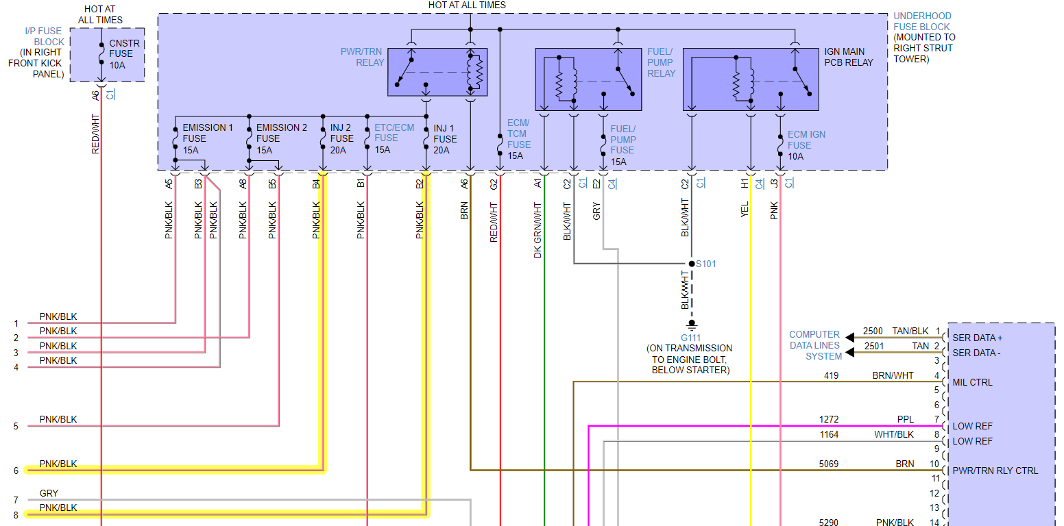
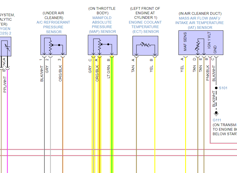
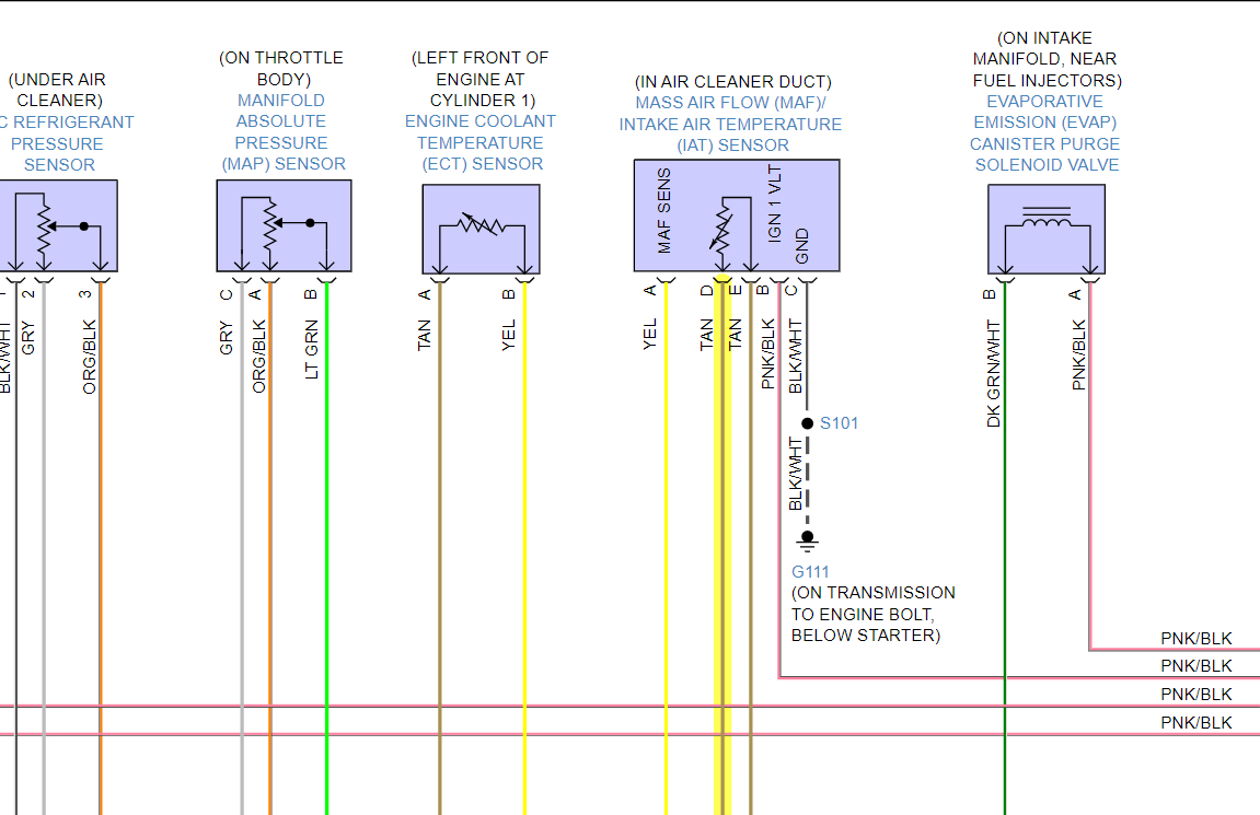
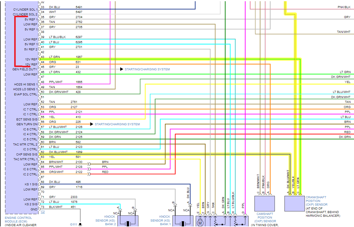
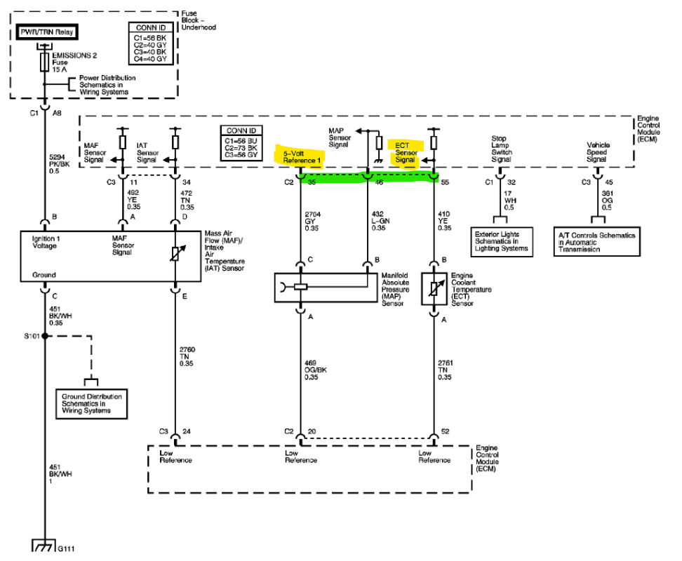
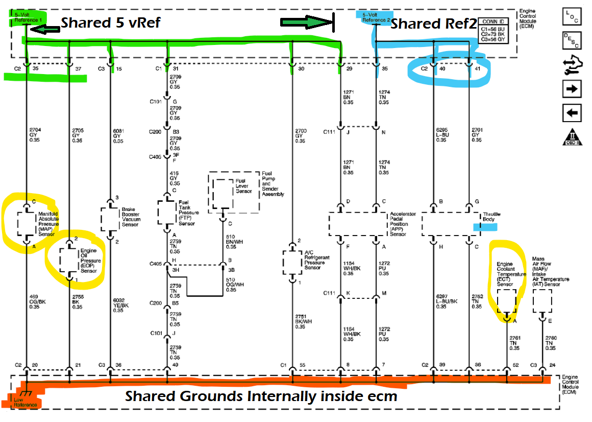
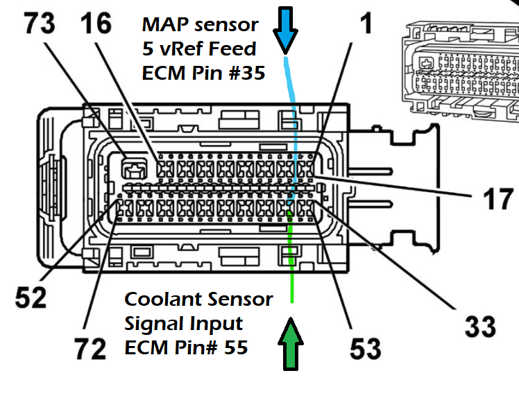
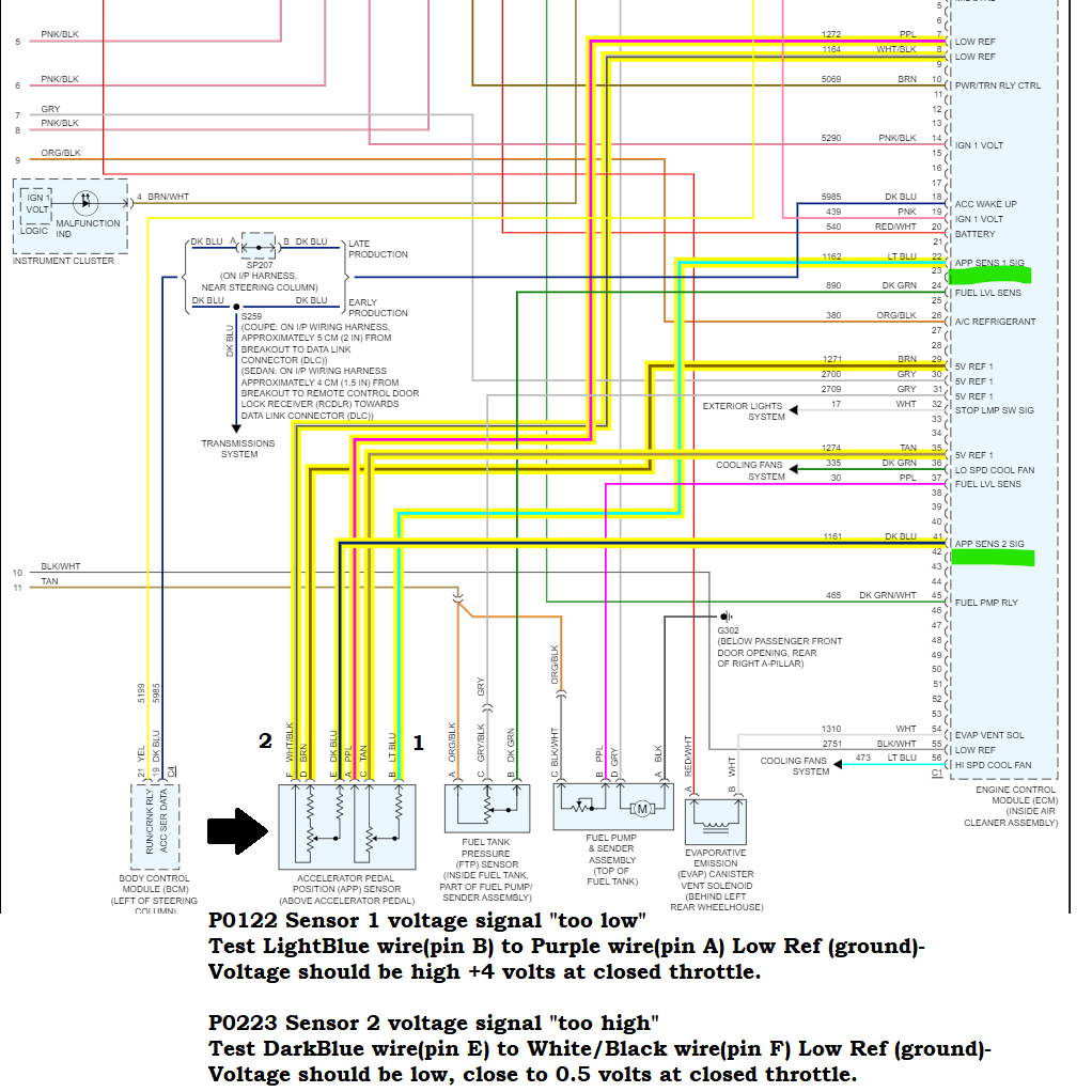
Okay, well we've found some problems then, 5-volt Ref 1 (Pin 37 Grey wire is that Map sensor Reference voltage) so it's not making it from the ECM to the map sensor,
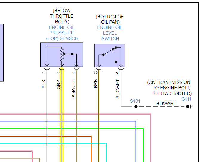
5-volt Ref 1 (pin 35 is the Reference voltage for the Oil Pressure Sensor.
Pins 40 and 41 may be a 5-volt Ref shared internally inside the ECM.
Pins 43 and 44 I'm not super worried about your reading battery voltage there, it just be might a little low because of the key being on during testing.
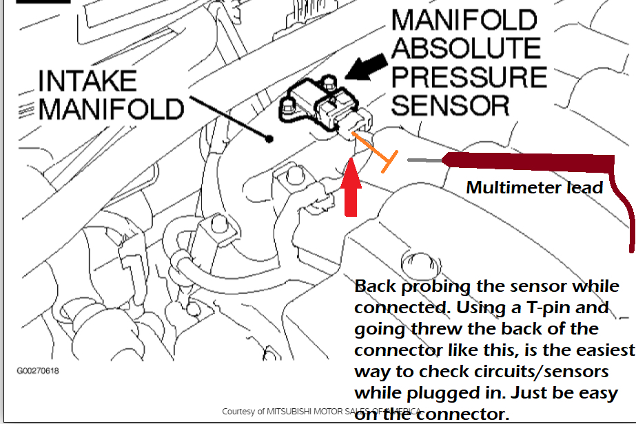
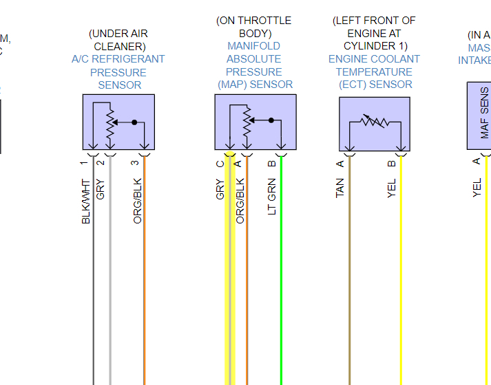
So, first thing, with the key off, unplug the oil pressure sensor and MAP sensor let's see if either one of them is pulling the Reference voltage down, any sensor that's uses a 5-volt Ref can short out and pull the whole circuit to ground.
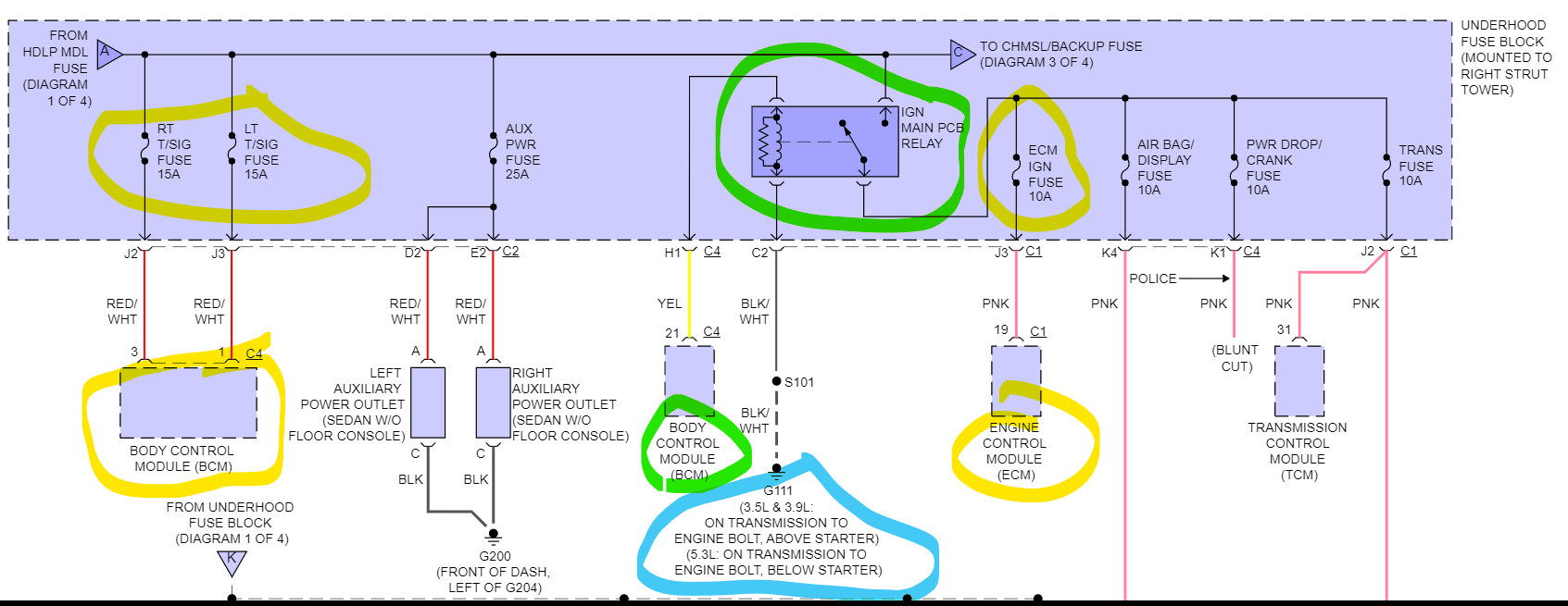
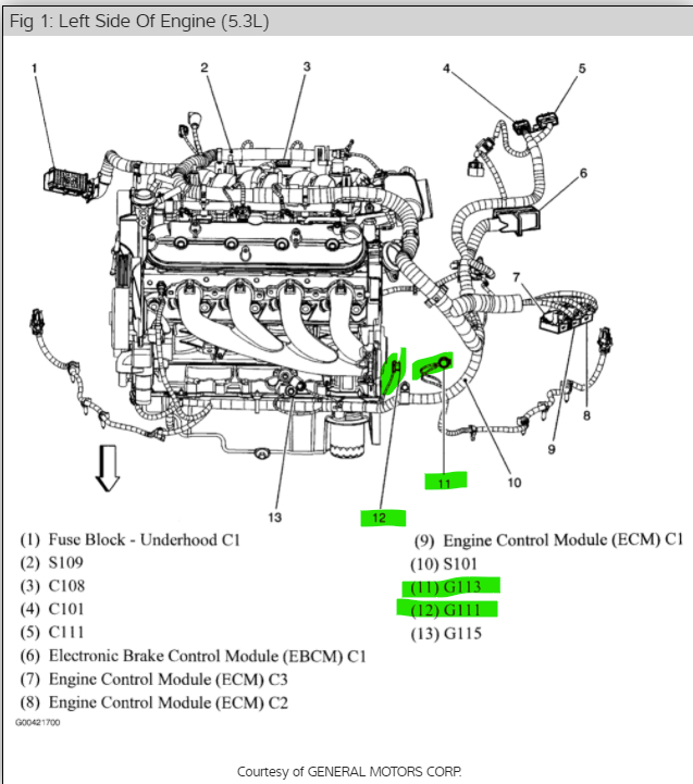
1st diagram is the Oil Pressure sensor it looks like it's under the throttle body, unplug that and the MAP sensor, turn the key back on and see if you have 5 volts at both sensors and at the ECM pins 37 and 35, they may be a shared Ref voltage inside the ECM as well. If the 5 volts come back, turn the key off, and plug one sensor back in at a time and see which one is shorted out, because the 5 volts will disappear again.

Also, just FYI, when a sensor shorts out and pulls the circuit down, it can disable the ECM completely.
Feb 14, 2022 at 1:29 PM
Avatar
RONALD DEVOLD
  • MEMBER
  • 134 POSTS
Okay, I will get back.
Feb 14, 2022 at 2:46 PM
Avatar
AL514
  • CERTIFIED EXPERT
  • 5,462 POSTS
Okay, after going through everything and looking up some code setting criteria, I have a theory as to what might be happening. This is just hypothesis, but I found that the Coolant Sensor code P0118 can be set if the sensor is shorted to a separate/different 5-v Ref wire. And I thought it was strange that you were getting 0/Ground voltage signal on ECM Pin #35 but still getting 4.9 volts at the Map sensor (pin #35 is the Map sensors 5vRef).

So, then I looked at the Chevrolet OEM diagrams and found that the Coolant Sensor signal input wire to the ECM and the MAP sensors 5v Ref feed wire pins at the ECM are right next to each other. I will put the diagrams below. I think the Map sensor 5vRef is shorting to the Coolant sensors input Signal wire at the ECM connector, there might be a bent pin there or some corrosion, but it makes sense that the Map sensors signal would be low, and the Coolant sensors signal would be High input just like the first 2 codes you're getting.

I'm not sure if you unplugged the ECM C2 connector or not, but I think this is what's happening, after seeing where the pin locations were and that the coolant sensor code can set due to a "different Reference voltage being shorted to it", this would explain why you're not reading anything at ECM pins 35 and 37, I just wondering why you're not getting any other codes, unless it's because the Map sensors Ref V is first in line and being pulled down first, therefore messing with the ECM.

Watch I'll probably be wrong after all that, but do a real good inspection of that C2 ECM connector and the pins in the ECM side of the connection.

Try the suggestions about the Oil Pressure sensor and MAP sensor also in the previous post. Just to be sure of what's happening here. I want to be sure we know what we're dealing with. A clue too was the new codes you got, something got messed with when the wiring harness was moved around for testing.
Feb 14, 2022 at 6:55 PM
Avatar
RONALD DEVOLD
  • MEMBER
  • 134 POSTS
I don't know how but the 5v reference is reading at the sensors and ECM. i unplugged them and there was voltage at both sensors and ECM. and also, once i plugged them back one at a time.
Feb 15, 2022 at 6:43 AM
Avatar
AL514
  • CERTIFIED EXPERT
  • 5,462 POSTS
It's because either you've moved the harness away from an area it was shorting out on, or one of those sensors has a pin fitment issue. Does the vehicle start now? And did you inspect the ECM connectors?
Whatever wires you've moved around during all this, that is your problem area with the harness, there has to be a corroded connection or loose pin fitment going on somewhere where your hands have been. This is why we don't move wiring harnesses around too much during testing, because you can accidentally fix the problem and not know where it actually is.
Feb 15, 2022 at 10:44 AM
Avatar
RONALD DEVOLD
  • MEMBER
  • 134 POSTS
okay. i will double check all wires and see if i can mount the ECU back and still back probe the wires. And the vehicle still will not start.
Feb 15, 2022 at 11:08 AM
Avatar
AL514
  • CERTIFIED EXPERT
  • 5,462 POSTS
It might be a pin fitment issue right at the ECM, if you're moving that ECM around to get at those connectors so you can back probe them, look at the pins themselves, even a slight bend on one of them can short it to another pin, I mean look at where they put the ECM, it's not in a protected place from moisture or anything else, With moving it around like that something happened. Also did you see if you have 12 volts at the crank sensor? If it's still a crank, no start, and you have a crank sensor code. Go right for the sensor, check that it has 12-volt feed, a good ground, check the connector on that sensor too, I think you're right in the area of getting this thing figured out. Those reference voltages needed to be restored and it needs a crank signal to start and fire the coils and injectors.
Look for basic stuff, don't over think it. You're really close, granted you may have a bad crank sensor, but this car was a no crank to begin with, then no 5-v Ref. then 3 new codes, then 5-v Ref back again, this has a wiring issue. I'm going to pull up the diagrams for the ECM Grounds as well. So, we know where those are.

This ECM only has one Ground as well, and the Ignition Coils ground right next to the ECM ground. Diagrams below.
Feb 15, 2022 at 11:18 AM
Avatar
RONALD DEVOLD
  • MEMBER
  • 134 POSTS
So, I know it's been some time since last touched basis, but finally I have the time to jump back on my project. So here is what I have now:
P0122-Throttle Position Sensor 1 Circuit Low Voltage
P0223-Throttle Position Sensor 2 Circuit High Voltage
P0315-Crankshaft Position System Variation Not Learned
P0335-Crankshaft Position Sensor ‘A’ Circuit Malfunction
I will focus on the Crankshaft codes. the 3 wires going to the sensor are LT-GN(12v REF), D-BLU/WHT(CKP SENSOR SIGNAL) and YE/BK(Low Reference)
With key on I am getting the 12v REF, THE LOW REFERENCE, but I'm only getting .09-1.9v on the signal wire while cranking. I don't know what reading I should be getting on the signal wire. Another thing that has me scratching my head is, how can I perform a crank sensor relearn with an engine that is not running?
Jun 24, 2022 at 9:55 AM
Avatar
AL514
  • CERTIFIED EXPERT
  • 5,462 POSTS
Okay, since you have 12-volts at the sensor, that's good, but what they want you to do is even if you have 12-volts across the power feed and low ref(ground), they want you to do a semi load test to verify both power and ground circuits are actually okay. This is a pretty quick test, they want you to connect a regular automotive 12-volt test light across the 12-volt feed and sensor signal wire momentarily (so not very long), and the Fuel pump should come on, so only do this test long enough to hear the pump or watch your fuel pressure gauge jump up. This will simulate the engine running and verify your power and ground for the sensor. Once you do this test, and I'm going to assume the fuel pump will come on.
After that it says to inspect the crankshaft sensor for 1. any wiring routed too close to Secondary Ignition sources (coils, plugs, etc.), check that the gap at the sensor is ok and that there is nothing wrong with the trigger wheel or anything obstructing the sensor (dirt, oil, etc). anything that may affect the signal. I know that if there is an excessive gap at the sensor it can throw off the reading. If you pull out the crank sensor and the end of it is all scratched up or has been rubbing on anything you should be able to see it pretty easy. You are most likely going to be changing the sensor anyway. It looks like it's just one bolt to hold it into the engine block. The new sensors usually come with a sticker type piece on the front of the sensor where it picks up its signal, which is there to set the gap to the trigger wheel. This one doesn't look adjustable, but just so you know not to remove that sticker.

Not sure where you are testing the sensor from, it looks like it's under the exhaust manifold, it says to remove the manifold to replace the sensor, but I would see if you can get to it without having to do that. If you are testing it from a different location, then inspection of its connector and the wiring down to it is needed. I will get all the relearn info for you, as well as the other TPS code info. The relearn might be hindered if there are other codes stored that have to do with engine controls as well. I'll post the rest as I get it together here real quick.

And are you doing the relearn with a scan tool?
Jun 24, 2022 at 11:16 AM
Avatar
AL514
  • CERTIFIED EXPERT
  • 5,462 POSTS
The first three diagrams are for the TPS codes and testing. Pages 4 to 6 are for the Crankshaft Position sensor code and testing. The last two pages are the Crankshaft Position sensor Variation Relearn Procedure. Make sure you clear all codes before doing any re-learn procedure. That includes taking care of the APP (TPS) sensor on the gas pedal. It sounds like it might have shorted out internally. It has two Throttle Position Sensors built into one. So, there's two 5-volt reference wires, two signal wires, and two grounds going to the ECM. Both the signals go opposite each other with throttle (pedal) movement. So, one goes around 4-volts down and the other around 0.5-volts up.

https://www.2carpros.com/articles/crankshaft-angle-sensor-replacement
Jun 24, 2022 at 1:35 PM
Avatar
RONALD DEVOLD
  • MEMBER
  • 134 POSTS
I replaced the crank sensor and still getting the same results. I am unable to retrieve the other feed, so I think I am at a dead end with this issue.
Jul 2, 2022 at 10:16 AM
Avatar
AL514
  • CERTIFIED EXPERT
  • 5,462 POSTS
You're still only getting around two volts from the crank shaft signal wire? Or are you getting a different voltage reading now? If the reading is still that low. It's probably something to do with the trigger wheel for the crankshaft sensor. If the sensor is not close enough to the trigger wheel it won't send the full voltage signal because the magnetic field is not being interrupted enough by the trigger wheel. The trigger wheel on this vehicle has 24 teeth, as each tooth passes the crankshafts sensors magnets it creates a pulse to the ECM. There could be a problem with the trigger wheel.
You should check to see that the crankshaft has not become magnetized. Shafts can become magnetized when there are main Ground wires that are in the wrong place. For example, if a ground has been moved to the engine block from some other location. The Ground location G111 should go from the Transmission to Engine just above the Starter motor. If a main ground like that has been moved to a place where it should not be, the current flow from the Starter Motor will find new ground path and it can end up magnetizing the Crankshaft, a Camshaft, etc. When that happens sensors like this won't read correctly. So, I would take a small screwdriver that you know is not magnetic, and just touch the end of the Crankshaft and see if it has become magnetized. This is why grounds are put in specific locations. But check to see if that may be what's happening. See if the small screwdriver sticks to the end of the crankshaft. Also, if you notice any ground wires besides the one that should be about two inches from the Starter motor.
This usually happens when a ground near the Starter has been moved because the Starter has such a huge current draw, much more than any other component. I'll try to find a video on this so you can get a better idea of this situation.

Watch this whole video, this is all about shafts getting magnetized. The vehicle in this video is having an issue with the crankshaft signal not being strong enough.
If you're getting some other voltage reading higher than the 1.9volts you were getting let me know.

https://www.youtube.com/watch?v=2eApL4UPT4Q
Jul 2, 2022 at 2:32 PM