Removal procedure is below for you.
Roy
All vehicles
1. Refer to: Jacking and Lifting - Overview See: Vehicle Lifting > Procedures > Jacking and Lifting (100-02 Jacking and Lifting, Description and Operation).
2. Refer to: Fuel System Pressure Release See: Fuel Pressure Release > Procedures > Fuel System Pressure Release (310-00A Fuel System - General Information - 1.6L EcoBoost (110kW/150PS)- Sigma, General Procedures).
3. Refer to: Air Conditioning (A/C) System Recovery, Evacuation and Charging See: Heating and Air Conditioning > Procedures > Air Conditioning (A/C) System Recovery, Evacuation and Charging (412-00 Climate Control System - General Information, General Procedures).
4.
imageOpen In New TabZoom/Print
5. Refer to: Cooling System Draining and Vacuum Filling See: Cooling System > Procedures Cooling System Draining and Vacuum Filling (303-03A Engine Cooling - 1.6L EcoBoost (132kW/180PS)- Sigma, General Procedures).
6. Refer to: Cowl Panel See: Cowl > Removal and Replacement > Cowl Panel (501-02 Front End Body Panels, Removal and Installation).
7.
imageOpen In New TabZoom/Print
8.
imageOpen In New TabZoom/Print
9.
imageOpen In New TabZoom/Print
10.
imageOpen In New TabZoom/Print
11. Refer to: Air Cleaner See: Air Filter Element > Removal and Replacement > Air Cleaner (303-12A Intake Air Distribution and Filtering - 1.6L EcoBoost (132kW/180PS)- Sigma, Removal and Installation).
12. NOTE: If equipped with block heater.
imageOpen In New TabZoom/Print
13.
imageOpen In New TabZoom/Print
14.
imageOpen In New TabZoom/Print
15.
imageOpen In New TabZoom/Print
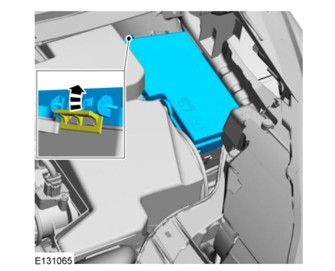
16. Refer to: Battery Tray See: Battery Tray > Removal and Replacement > Battery Tray (414-01 Battery, Mounting and Cables, Removal and Installation).
17.
imageOpen In New TabZoom/Print
18.
imageOpen In New TabZoom/Print
19.
imageOpen In New TabZoom/Print
20.
imageOpen In New TabZoom/Print
21.
imageOpen In New TabZoom/Print
22.
imageOpen In New TabZoom/Print
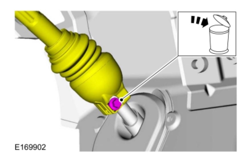
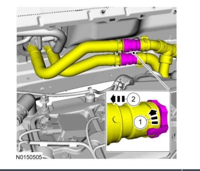
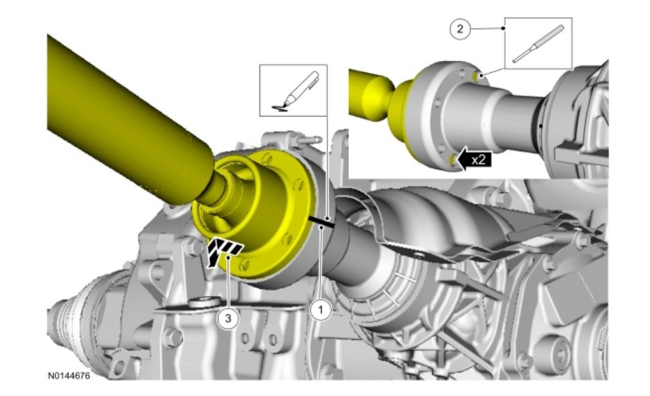
23. NOTE: Always wrap the fuel line connection with a towel before disconnecting it.
Refer to: Spring Lock Couplings See: Fuel Line Coupler > Procedures > Spring Lock Couplings (310-00A Fuel System - General Information - 1.6L EcoBoost (110kW/150PS)- Sigma, General Procedures).
Use Special Service Tool: 310-250 Disconnect Tool, Fuel Line.
imageOpen In New TabZoom/Print
24.
imageOpen In New TabZoom/Print
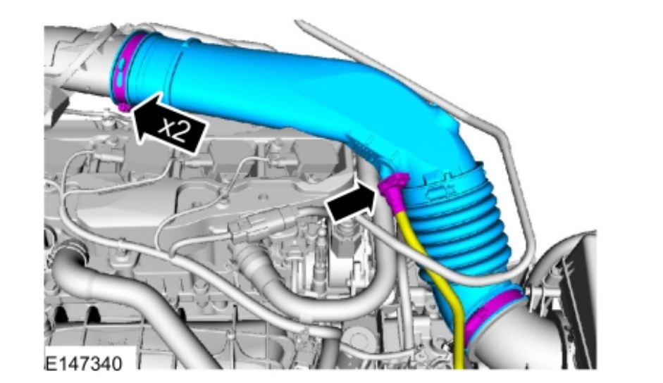
25. Use the General Equipment: Hose Clamp Remover/Installer
imageOpen In New TabZoom/Print
26.
imageOpen In New TabZoom/Print
27.
imageOpen In New TabZoom/Print
28.
imageOpen In New TabZoom/Print
29. Refer to: Degas Bottle See: Coolant Reservoir > Removal and Replacement > Degas Bottle (303-03A Engine Cooling - 1.6L EcoBoost (132kW/180PS)- Sigma, Removal and Installation).
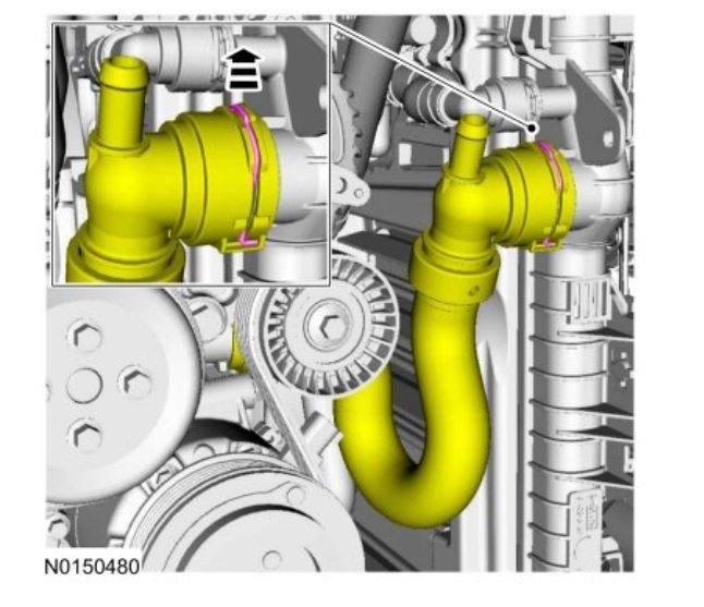
30. Use the General Equipment: Hose Clamp Remover/Installer
imageOpen In New TabZoom/Print
31.
imageOpen In New TabZoom/Print
32.
imageOpen In New TabZoom/Print
33.
imageOpen In New TabZoom/Print
34.
imageOpen In New TabZoom/Print
35.
imageOpen In New TabZoom/Print
36. Remove the front wheels and tires.
Refer to: Wheel and Tire See: Wheels and Tires > Removal and Replacement > Wheel and Tire (204-04A Wheels and Tires, Removal and Installation).
37.
imageOpen In New TabZoom/Print
38.
Remove the drain plug and drain the engine oil.
Use the General Equipment: Oil Drain Equipment
Install the drain plug.
Torque : 21 lb.ft (28 Nm)
imageOpen In New TabZoom/Print
39. Use the General Equipment: Strap Wrench
Use the General Equipment: Oil Drain Equipment
imageOpen In New TabZoom/Print
40.
imageOpen In New TabZoom/Print
41.
imageOpen In New TabZoom/Print
42.
imageOpen In New TabZoom/Print
43.
imageOpen In New TabZoom/Print
44.
imageOpen In New TabZoom/Print
Vehicles with
45.
imageOpen In New TabZoom/Print
46.
imageOpen In New TabZoom/Print
All vehicles
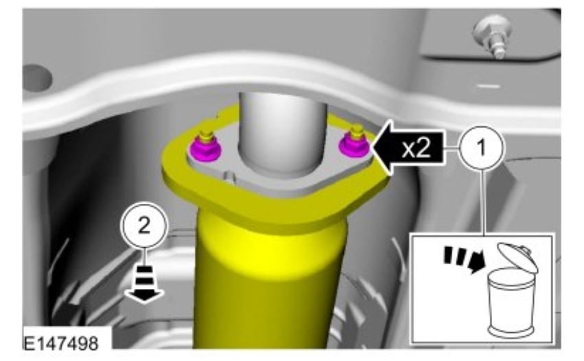
47. NOTE: Discard the O-ring seals and gasket seals.
imageOpen In New TabZoom/Print
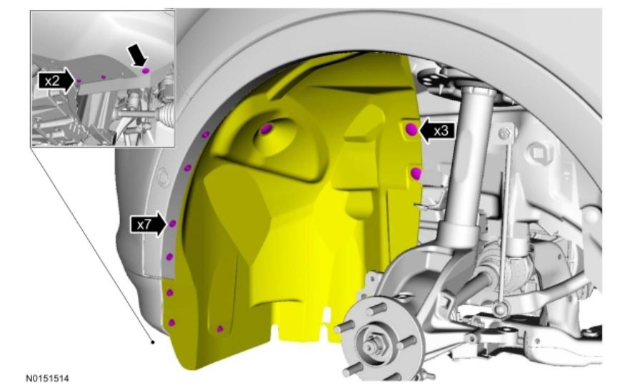
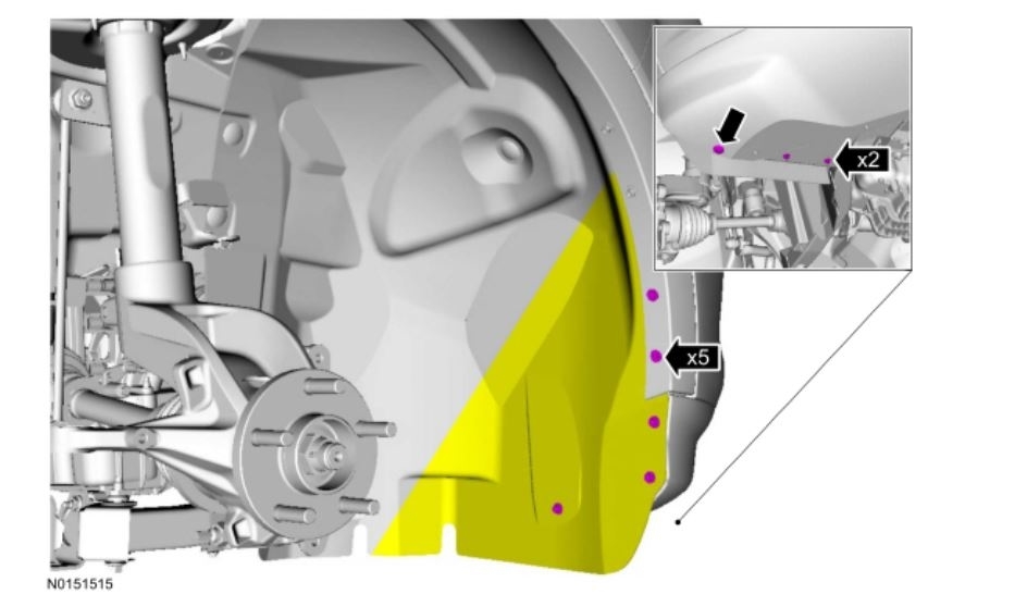
48. NOTE: LH shown, RH similar.
Both sides.
imageOpen In New TabZoom/Print
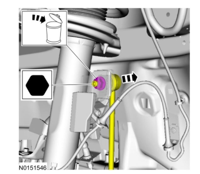
49. NOTICE: Use the internal or external hex-holding feature to prevent the ball and stud from turning while removing or installing the stabilizer bar link nuts. The link boot seal must not be allowed to twist while tightening the link nuts or damage to the boot seal will occur.
NOTE: LH shown, RH similar.
Both sides.
imageOpen In New TabZoom/Print
Images (Click to enlarge)
May 1, 2020 at 11:26 AM