Electronic throttle moto relay

2005 NISSAN MURANO
56,745 MILES • 3.6L • 6 CYL • 2WD
Avatar
ANDRIN ATEM
  • MEMBER
  • 393 POSTS
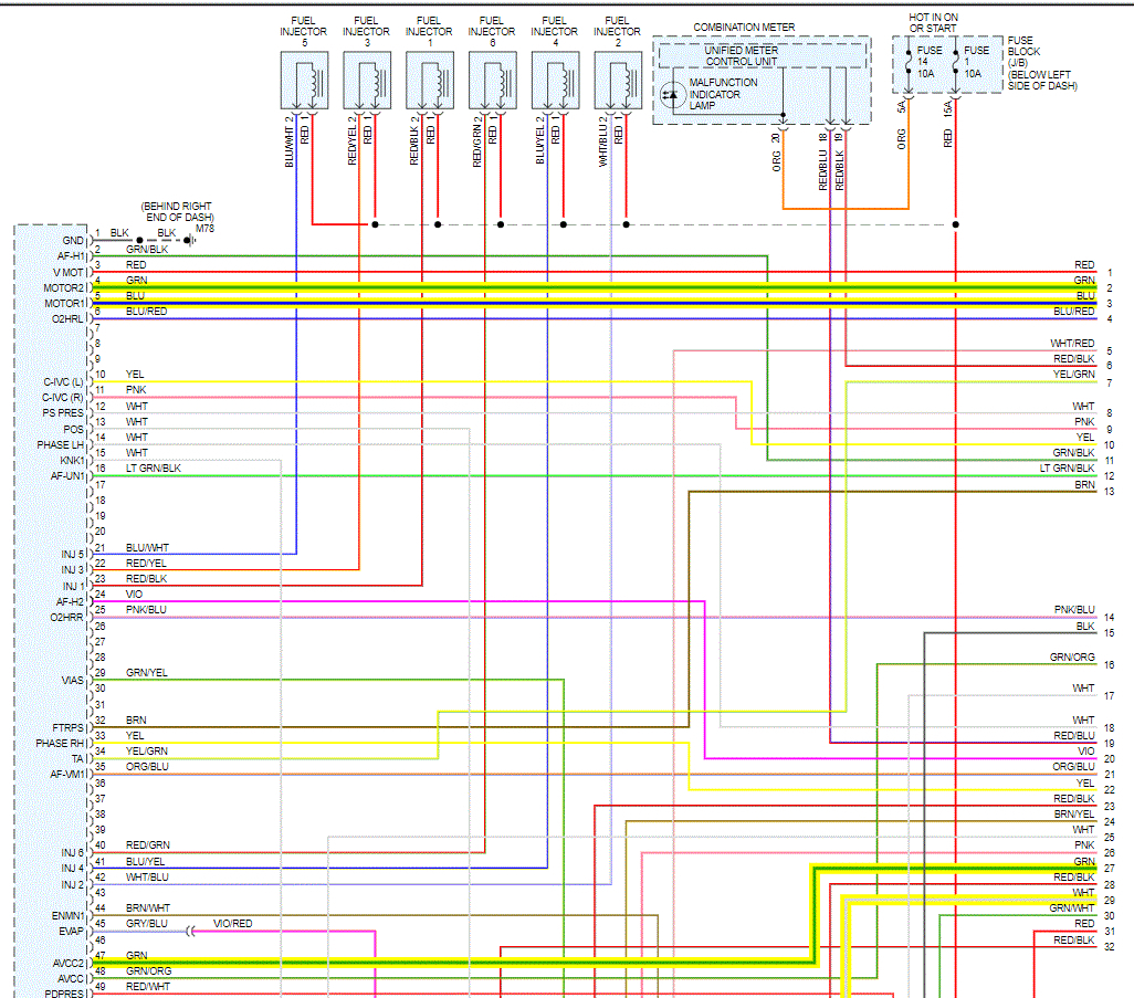
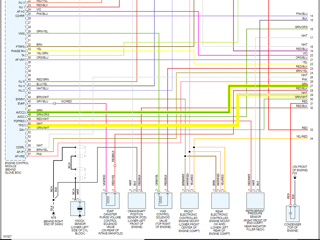
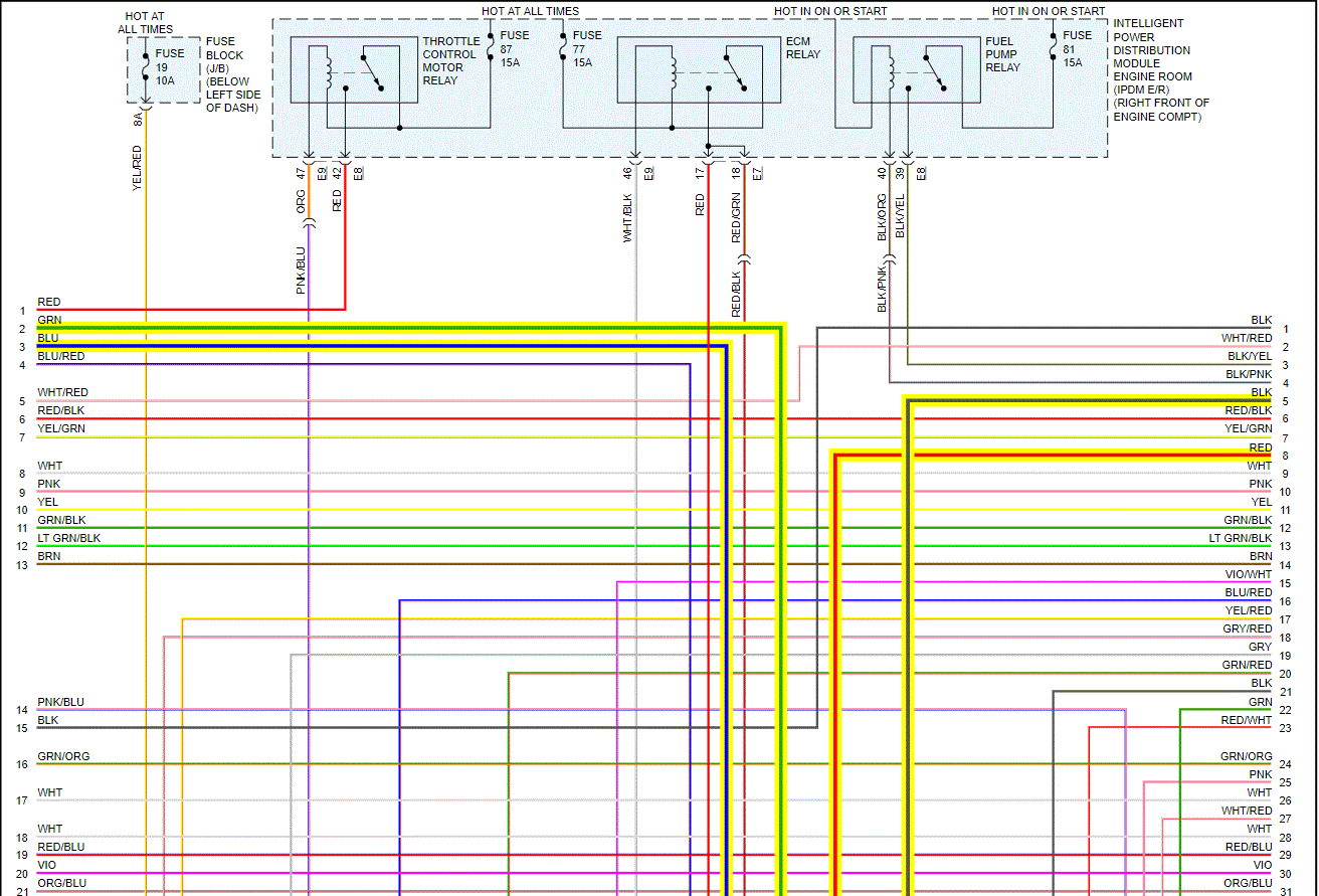
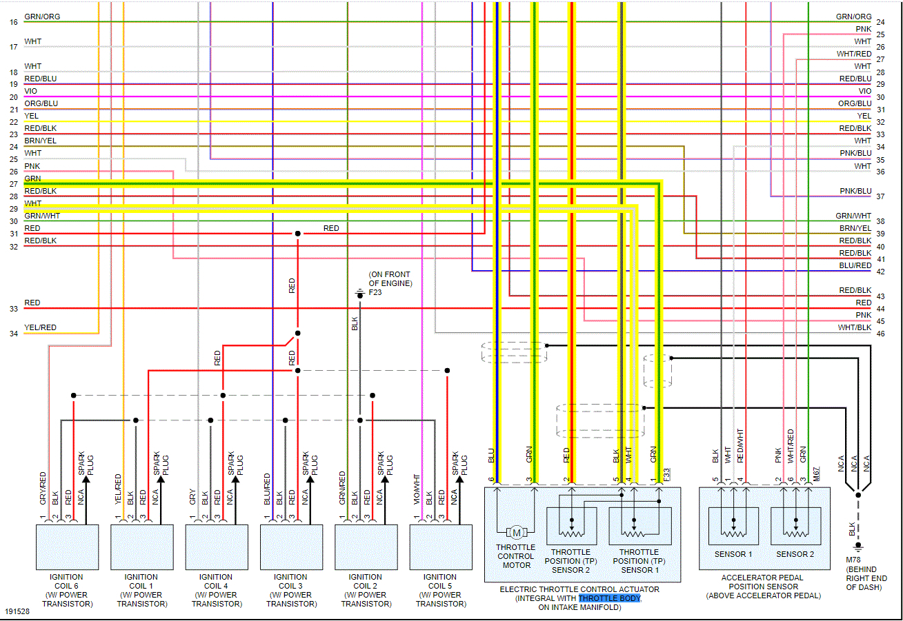
Thank you. i got this worry with a live data on the throttle moto relay shows of while the car idles. My question is, should the throttle body relay on IDPM fuse box stays on while vehicle idles, or it is normal to be off while engine is running. Secondly, when does the throttle moto relay comes on, when key is opened to acc? The car will not accelerate while on idling. Before replacing the electronic throttle body, i need to be sure i got no issues with the relay. Thanks.
Apr 29, 2021 at 1:32 PM
Advertisement
Avatar
JACOBANDNICKOLAS
  • CERTIFIED EXPERT
  • 110,175 POSTS
Hi,

The electronic throttle control relay is on when the key is in the run position and not accessory. Power supply for the throttle control motor is provided to the ECM via the throttle control motor relay. The throttle control motor relay is ON/OFF controlled by the ECM. When the ignition switch is turned ON, the ECM sends an ON signal to the throttle control motor relay, and battery voltage is provided to the ECM. When the ignition switch is turned OFF, the ECM sends an OFF signal to the throttle control motor relay, and battery voltage is not provided to the ECM.

Let me know if this answers your question.

Take care,

Joe
Apr 30, 2021 at 8:55 PM
Avatar
ANDRIN ATEM
  • MEMBER
  • 393 POSTS
So when the car is idling, the relay stsys on? Or when driving the relay stays on or of? Thanks very much. I have understood the first explaination.
May 1, 2021 at 3:58 AM
Advertisement
Avatar
JACOBANDNICKOLAS
  • CERTIFIED EXPERT
  • 110,175 POSTS
Hi,

When the key is on, the relay has power, regardless if it is running or not.

Let me know how things turn out for you. I'm interested in knowing.

Take care,

Joe
May 1, 2021 at 7:46 PM
Avatar
ANDRIN ATEM
  • MEMBER
  • 393 POSTS
Thanks.
May 3, 2021 at 1:15 AM
Avatar
JACOBANDNICKOLAS
  • CERTIFIED EXPERT
  • 110,175 POSTS
Hi,

You are very welcome. If you have a chance, let me know how things turn out for you or if you have other questions.

Take care,

Joe
May 3, 2021 at 5:28 PM
Avatar
ANDRIN ATEM
  • MEMBER
  • 393 POSTS
I will not hesitate to ask. Your services and guide has improve my understanding and ability to solve problems relating to car technology. I could not have solved so may problems without 2CarPros. I will always come back when i need more ideas. Thanks again
May 4, 2021 at 1:43 AM
Avatar
JACOBANDNICKOLAS
  • CERTIFIED EXPERT
  • 110,175 POSTS
You are very welcome. I don't want you to have more problems, but I do hope to see you again in the future. LOL

Also, would you consider leaving us a rating. It would be appreciated.


https://www.google.com/search?q=2carpros&gs_ivs=1#lrd=0x80dcd47364be5d0d:0xba091aa4209f4497,1,,,&tts=0

and

https://www.sitejabber.com/reviews/2carpros.com


Take good care of yourself,

Joe
May 4, 2021 at 6:57 PM
Avatar
ANDRIN ATEM
  • MEMBER
  • 393 POSTS
Please, could you help me understand what voltages goes to the 6 wired cables which goes into the electronic throttle body.. The red cable when tested with key on and engine running, i notice zero voltage, normally, when the relay stays on, i am suppose to get 5v or 12 volt of the red colored cable which enter the electronic body.
Jul 14, 2021 at 6:28 PM
Avatar
JACOBANDNICKOLAS
  • CERTIFIED EXPERT
  • 110,175 POSTS
Hi,

I need to get a better understanding. Normally, sensors will receive a 5v reference. I need confirmation of which wires you are referring to.

Let me know,

Joe
Jul 14, 2021 at 7:50 PM
Avatar
ANDRIN ATEM
  • MEMBER
  • 393 POSTS
The wires which connects to the throttle body itself. They are 6 wires.That goes or fits via a connector to the Throttle body.
Jul 15, 2021 at 1:35 AM
Avatar
JACOBANDNICKOLAS
  • CERTIFIED EXPERT
  • 110,175 POSTS
Hi,

If you look at the first 8 pics below, I provided the entire powertrain management wiring schematic. I had to cut them in half to make them readable, but I did overlap them so you can follow from one to the next.

Now, I highlighted all six of the wire you are referring to so you can have a visual of where they go and to help check them.

If you look at the very last pic below, it explains what the voltages are for the wires at the TB. For example, it explains to test the voltage to pin 50 on the PCM, which is the white wire between the PCM and the TB (TPS 1). It indicates what the voltage should be based on the throttle position.

If you look at pic 4, it shows the connection you are referring to at the throttle body.

Let me know if this helps or if you have other questions.

Take care,

Joe
Jul 15, 2021 at 8:43 PM