DTC P1133, how to check the signal wires with a multi-meter

2004 CHEVROLET SILVERADO
90,000 MILES • 4.8L • V8 • 2WD • AUTOMATIC
Avatar
RANDY1955
  • MEMBER
  • 71 POSTS
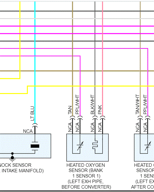
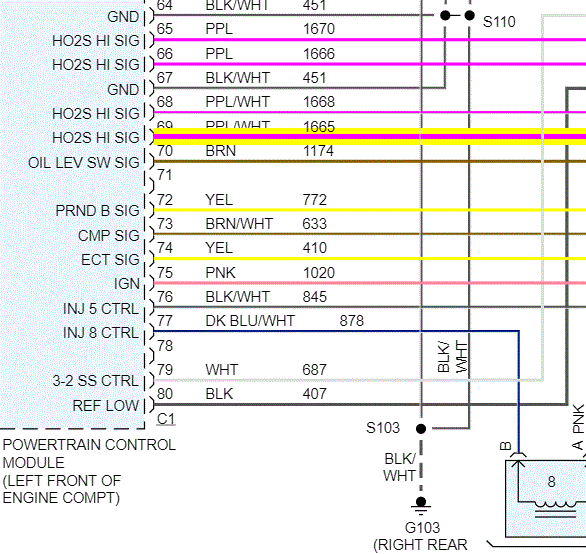
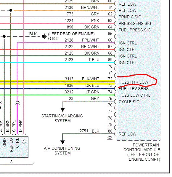
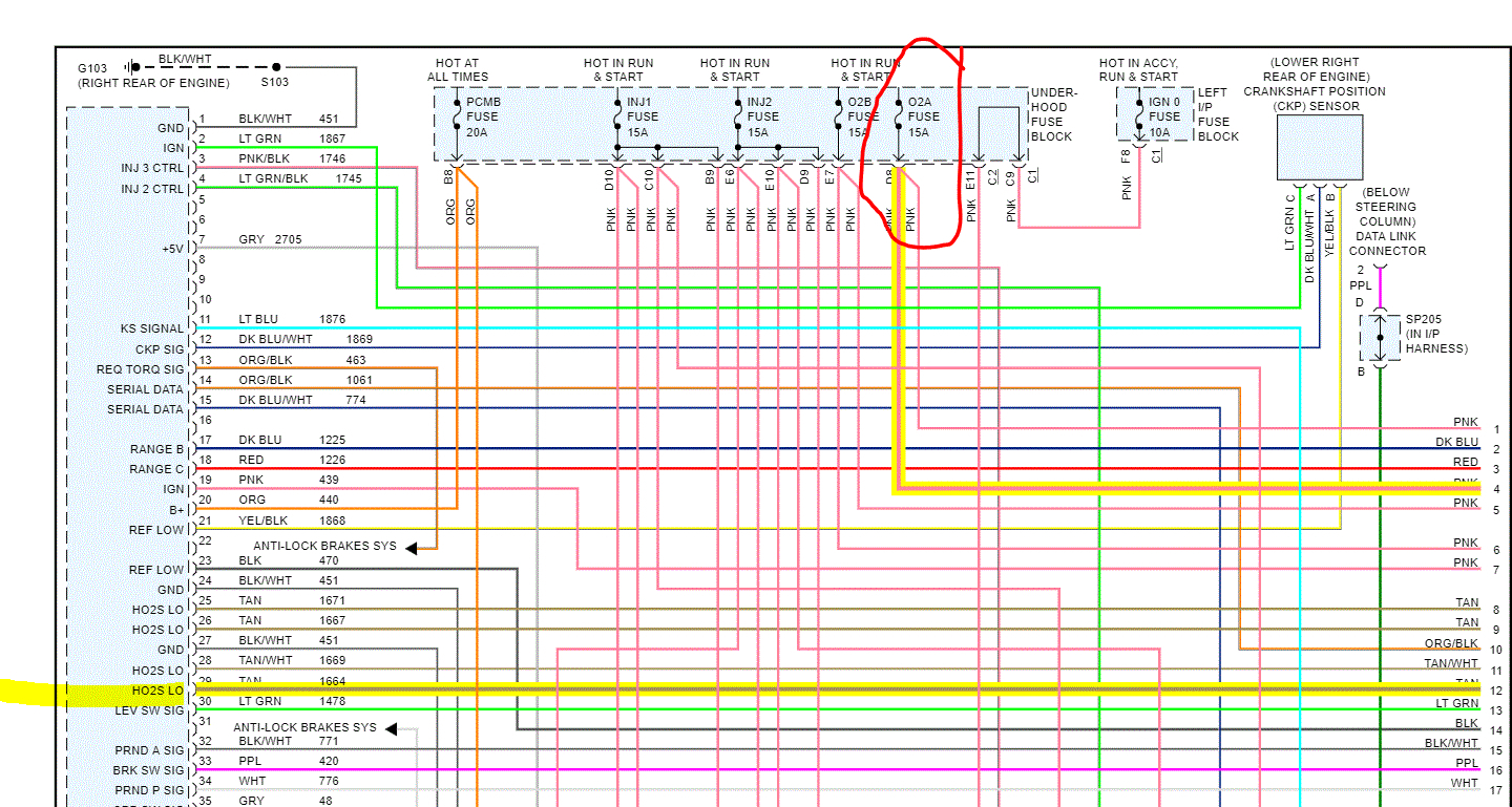
Bank one sensor one upstream oxygen sensor. I have tested the volts,ground on harness side. checked resistance on sensor itself it all checked out. I need to check the signal. can anyone tell me how to check the signal wires with a multi-meter? Thank you.
May 9, 2020 at 9:02 PM
Advertisement
Avatar
JACOBANDNICKOLAS
  • CERTIFIED EXPERT
  • 110,175 POSTS
Hi,

What you have to do is back probe the signal wire with the engine running and at operating temperature. Set your meter to 2v and start the engine. If it is working properly, it should osculate between .1 and .9V. If it is not changing, pull a vacuum hose off the intake and allow unmetered air to enter the engine. That should cause the voltage to drop. If there is no reaction, replace the sensor.

I hope this helps. Let me know if you have other questions.

Take care,
Joe
May 9, 2020 at 10:19 PM
Avatar
RANDY1955
  • MEMBER
  • 71 POSTS
Is that millivolts your talking about? Thank you for helping. My meter does not read millivolts I used mine today and the numbers were not fluctuating.
May 12, 2020 at 11:35 PM
Advertisement
Avatar
JACOBANDNICKOLAS
  • CERTIFIED EXPERT
  • 110,175 POSTS
Hi,

It is in volts. However, note that it never reaches 1 volt. The readings should fluctuate between 0.1v and 0.9v.

When you say the numbers weren't fluctuating, what was the reading? What was the engine temperature?

Joe
May 13, 2020 at 7:33 PM
Avatar
RANDY1955
  • MEMBER
  • 71 POSTS
Could it be possible to switch sensor one with two upstream and clear the code and see if the code moves?
May 15, 2020 at 9:03 PM
Avatar
JACOBANDNICKOLAS
  • CERTIFIED EXPERT
  • 110,175 POSTS
They are two different types. It won't work.

What are you finding when you test it?
May 15, 2020 at 10:20 PM
Avatar
RANDY1955
  • MEMBER
  • 71 POSTS
How do I know which wires are the signal wires on the sensor? it has 2 browns a pink and a purple with white strip. the ones I was using was the purple and one of the brown colored wires.And the reading was like .4 to .5 no higher I think I had the right huh.This stuff is all new to me I am just trying to help a good friend out so they can smog it and there behind doing this so.I appreciate all the help.
May 17, 2020 at 1:59 PM
Avatar
JACOBANDNICKOLAS
  • CERTIFIED EXPERT
  • 110,175 POSTS
Hi,

I attached pics below of the wiring. Pic 1 shows the sensor and wires from it. The remaining pics show where the wires go.

The purple with the white stripe is the signal. The pink is power by a specific fuse, the tan is low reference and the black/white is low also.

It sounds like you had the right wire for signal. Take a look through these and let me know if you have questions. Note that in the schematics, the wires right at the sensor indicate NCA. That means no color available. So right at the sensor the wire color may be different which will require you to go back to where it connects to see colors.

Hope this helps.

Joe
May 17, 2020 at 6:58 PM
Avatar
RANDY1955
  • MEMBER
  • 71 POSTS
I tested the purple with white strip wire and was 0.4 0.5 no higher no lower I used the oxygen sensor casing for a ground and engine at temperature level.I didn't pull a vacuum line because I have my meter underneath and the vacuum line was on top so I would have a hard time reading it.So what do you think I should do next? like I say I am grateful for the help.
May 20, 2020 at 8:25 PM
Avatar
JACOBANDNICKOLAS
  • CERTIFIED EXPERT
  • 110,175 POSTS
The voltages should be going up and down more than that. It sounds like you have a bad sensor. That is what I would do at this point. The only other way to see how it reacts is to remove a vacuum hose to see if makes a difference. However, I understand why you are having trouble doing it.

Let me know if it takes care of the problem.

Joe
May 20, 2020 at 8:47 PM