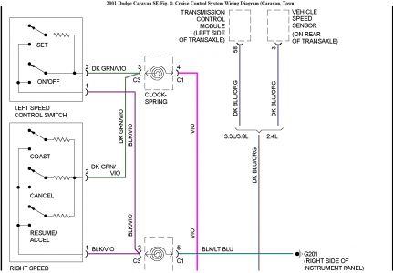
P1595 is the cruise control (speed control) circuit. Here's the testing info.
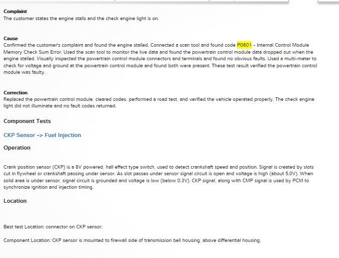
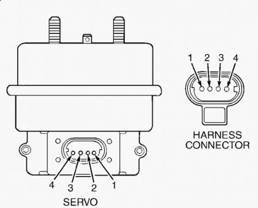
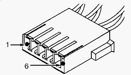
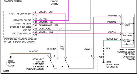
DTC P1595: SPEED CONTROL SOLENOID CIRCUITS DTC P1683: SPEED CONTROL POWER RELAY OR 12V DRIVER CIRCUIT NOTE: Both DTCs are diagnosed using the same test. After repairs, perform TEST VER-4A under VERIFICATION TESTS. DTC P1595 will set if vacuum and vent solenoids do not respond when actuated by PCM. DTC P1683 will set if Speed Control (S/C) power supply circuit is open or shorted to ground. Possible Causes Ground circuit open. "¢ Brake switch output circuit open. "¢ S/C power supply circuit open or shorted. "¢ S/C servo defective. "¢ S/C vacuum solenoid control circuit open or shorted. "¢ S/C vent solenoid control circuit open or shorted. "¢ Brake switch defective or out of adjustment. "¢ Defective PCM. "¢ Testing Turn ignition on. Turn Speed Control (S/C) on. Using scan tool, actuate S/C vent solenoid. Using scan tool, actuate S/C vacuum solenoid. If vacuum solenoid in S/C servo does not click, go to next step. If vent solenoid in S/C servo does not click, go to step 6 . If both solenoids do not click, go to step 10 . If both solenoids click, go to step 15 . 1. Turn ignition off. Disconnect S/C servo connector. Inspect connector and clean or repair as necessary. Turn ignition on. Turn S/C switch on. With test light connected to battery voltage, probe S/C servo connector terminal No. 1 (Violet/Yellow wire). See Fig. 4 . Using scan tool, actuate S/C vacuum solenoid. If test light does not blink off and on, go to next step. If test light blinks on and off, replace S/C servo. See SPEED CONTROL SERVO under REMOVAL & INSTALLATION. 2. Disconnect PCM connectors. Inspect connectors and clean or repair as necessary. Using DVOM, measure resistance of Violet/Yellow wire between S/C servo connector terminal No. 1 and PCM connector C2 terminal No. 56. See Fig. 3 . If resistance is less than 5 ohms, go to next step. If resistance is 5 ohms or more, repair open on Violet/Yellow wire. 3. Using DVOM, measure resistance between ground and S/C servo connector terminal No. 1 (Violet/Yellow wire). If resistance is 5 ohms or more, go to next step. If resistance is less than 5 ohms, repair short to ground on Violet/Yellow wire. 4. Replace PCM. 5. Turn ignition off. Disconnect S/C servo connector. Inspect connector and clean or repair as necessary. Turn ignition on. Turn S/C switch on. With test light connected to battery voltage, probe S/C servo connector terminal No. 2 (Violet/Orange wire). See Fig. 4 . Using scan tool, actuate S/C vent solenoid. If test light does not blink off and on, go to next step. If test light 6.blinks on and off, replace S/C servo. See SPEED CONTROL SERVO under REMOVAL & INSTALLATION. Disconnect PCM connectors. Inspect connectors and clean or repair as necessary. Using DVOM, measure resistance of Violet/Orange wire between S/C servo connector terminal No. 2 and PCM connector C2 terminal No. 80. If resistance is less than 5 ohms, go to next step. If resistance is 5 ohms or more, repair open on Violet/Orange wire. 7. Using DVOM, measure resistance between ground and S/C servo connector terminal No. 2 (Violet/Orange wire). If resistance is 5 ohms or more, go to next step. If resistance is less than 5 ohms, repair short to ground on Violet/Orange wire. 8. Replace PCM. 9. Turn ignition off. Disconnect S/C servo connector. Inspect connector and clean or repair as necessary. Turn ignition on. Turn S/C switch on. Connect test light between S/C servo connector terminal No. 3 (Violet/White wire) and ground. See Fig. 4 . If test light does not illuminate, go to next step. If test light illuminates, replace S/C servo. See SPEED CONTROL SERVO under REMOVAL & INSTALLATION. 10. Turn ignition off. Disconnect brake switch connector. Using DVOM, measure resistance of Violet/White wire between brake switch harness connector terminal No. 3 and S/C servo connector terminal No. 3. See Fig. 2 and Fig. 4 . If resistance is less than 5 ohms, go to next step. If resistance is 5 ohms or more, repair open on Violet/White wire. 11. Turn ignition on. Turn S/C switch on. With test light connected to ground, probe brake switch harness connector terminal No. 4 (Violet/Yellow wire). If test light does not illuminate, go to next step. If test light illuminates, replace brake switch. See BRAKE SWITCH under REMOVAL & INSTALLATION. 12. Turn ignition off. Disconnect PCM connectors. Inspect connectors and clean or repair as necessary. Using DVOM, measure resistance of Violet/Yellow wire between brake switch harness connector terminal No. 4 and PCM connector C1 terminal No. 5. See Fig. 2 and Fig. 3 . If resistance is less than 5 ohms, go to next step. If resistance is 5 ohms or more, repair open on Violet/Yellow wire. 13. Replace PCM. 14. Turn ignition off. Disconnect S/C servo connector. Inspect connector and clean or repair as necessary. With test light connected to battery voltage, probe S/C servo connector terminal No. 4 (Black/Light Green wire). If test light illuminates, go to next step. If test light does not illuminate, repair open on Black/Light Green wire and/or Black wire between S/C servo and ground. 15. Problem is intermittent. Check the following and repair as necessary: 16. Wiggle wiring while monitoring scan tool display. "¢ Operate vehicle under same conditions as when DTC was set (freeze frame data). "¢ Check Technical Service Bulletins (TSBs). "¢ Check wiring and connectors for damage or corrosion. "¢

Nov 22, 2019 at 7:06 PM
(Merged)