Hi and thanks for using 2CarPros.
They aren't really too easy, but with the right tools and some time, you can do it.
Here are the directions for replacing the front control arm bushings. The attached pictures correlate with the directions.
The bushings are the same on each side.
FRONT SUSPENSION
Guide link, removing and installing
Special tools, workshop equipment, testers, measuring instruments and auxiliary items required
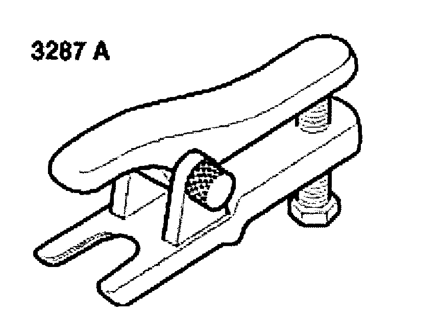
^ 3287A Ball joint puller
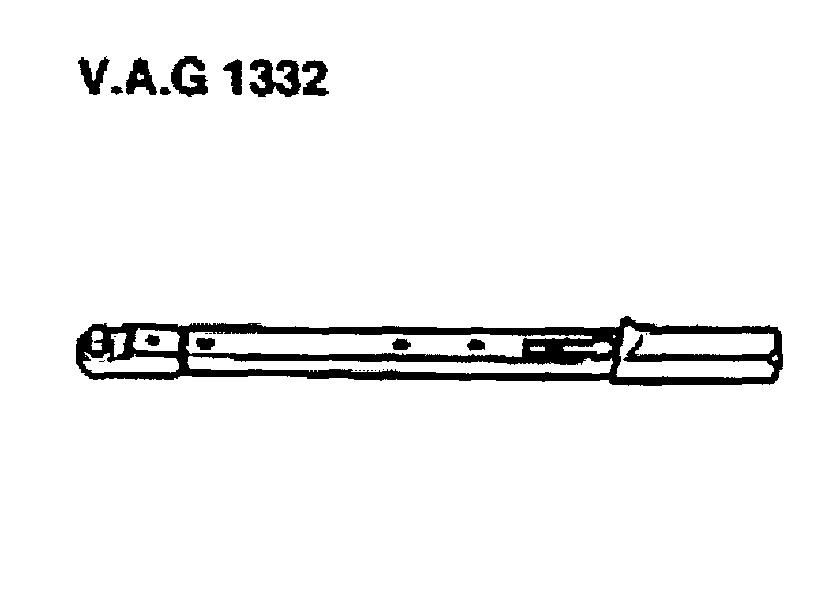
^ VAG 1332 Torque wrench
Removing
- Remove wheel.
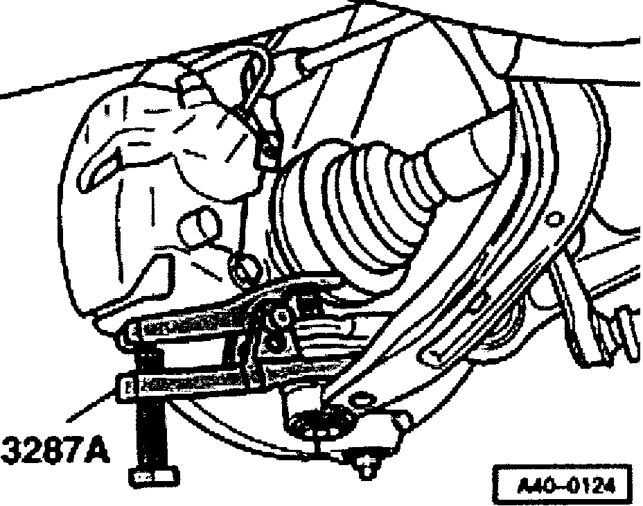
- Unscrew guide link joint pin nut and press off joint pin.
Vehicles with all-wheel-drive
- Unbolt propshaft from transmission.
Continued for all vehicles
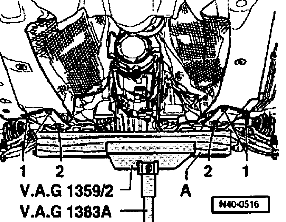
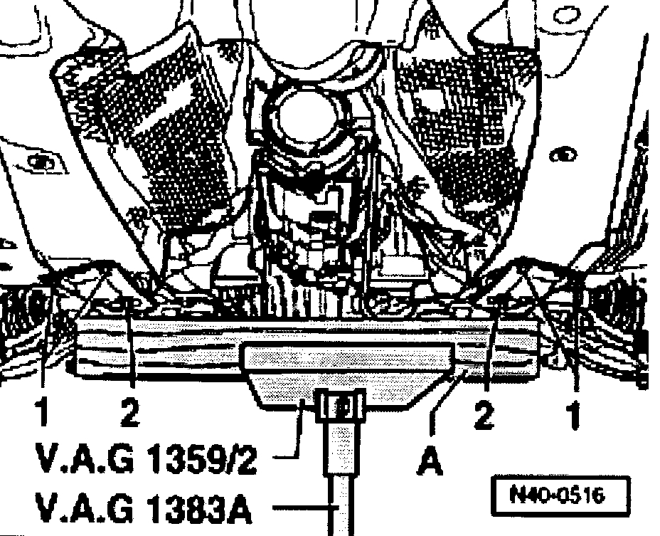
- Place transmission jack VAG 1383 A with 1359/2 under subframe and exert slight counter pressure.
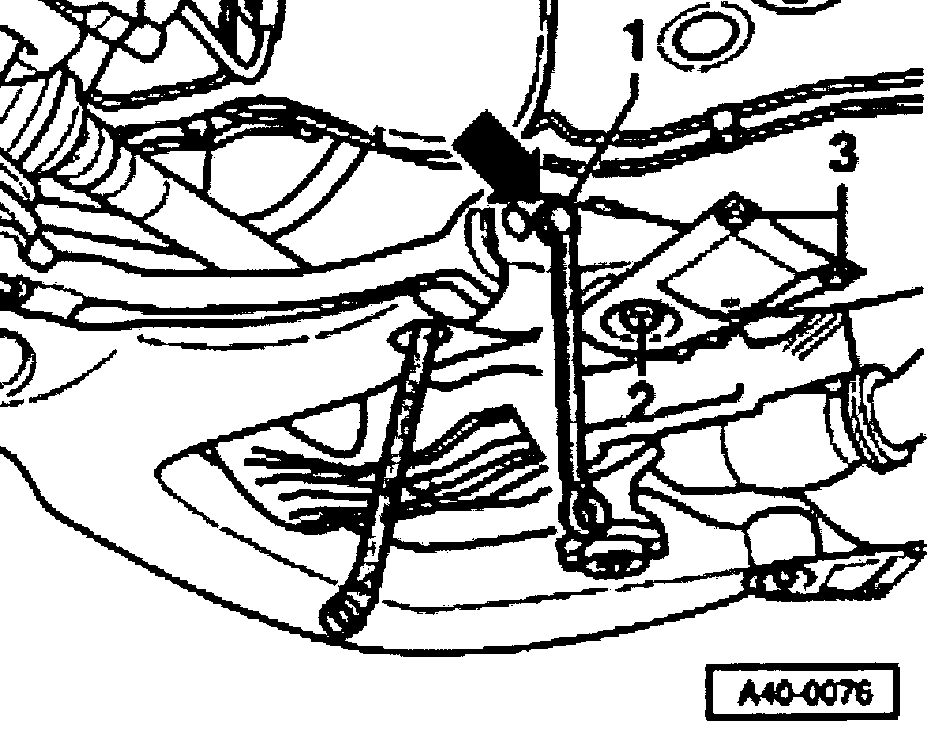
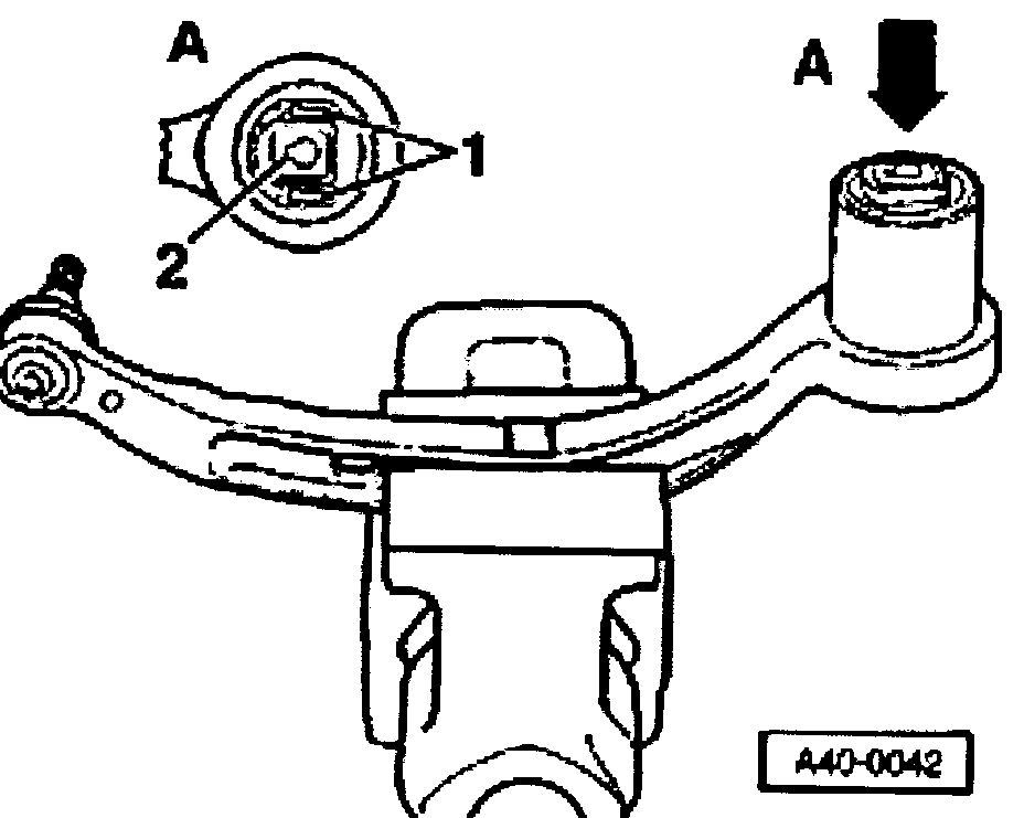
- Unscrew bolts -1- and -2- at rear of subframe on both sides of vehicle.
A - Block of wood
- Using transmission jack VAG 1383A, lower subframe slightly.
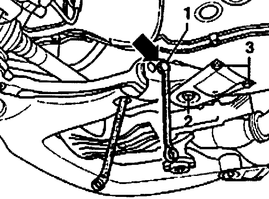
- Remove hex bolt -1-.
- Remove guide link.
Installing
- Insert guide link.
- Using transmission jack VAG 1383A, raise subframe slightly.
- Tighten bolts -1- and -2- at rear of subframe on both sides of vehicle.
A - Block of wood
- Tighten nut on joint pin
- Install new hex bolt -1- and new hex nut and tighten.
Notes:
^ Only use inner holes -arrow-.
^ Push guide link inward when tightening.
Vehicles with all wheel drive
- Bolt propshaft onto transmission.
Continued for all vehicles
- Install wheel and tighten.
Guide link mounting, replacing
Special tools, workshop equipment, test and measuring appliances and aux. items required
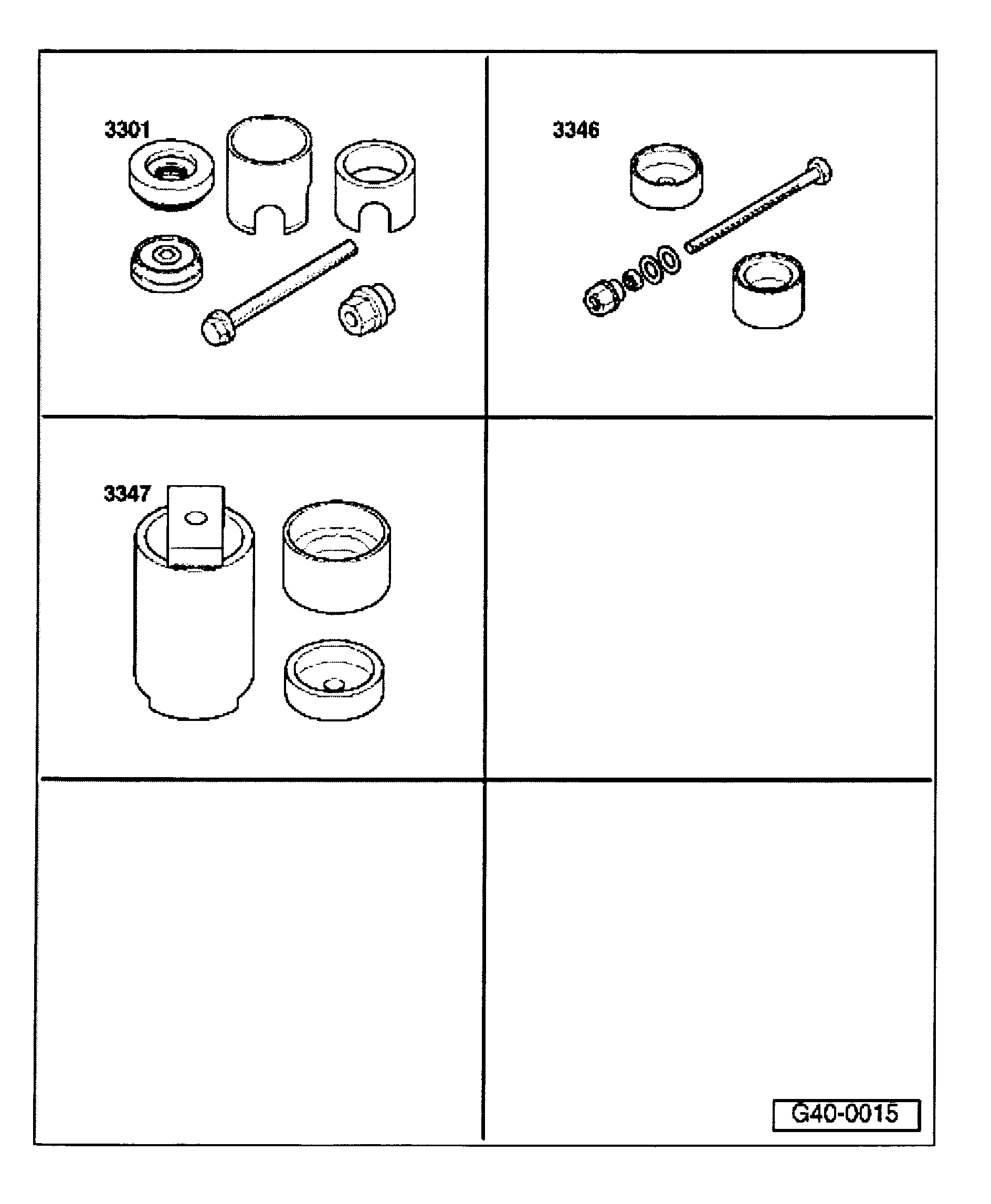
^ 3301 Assembly tool
^ 3346 Assembly tool
^ 3347 Assembly tool
Aluminum guide links must be clamped in a vice only with protective clamps!
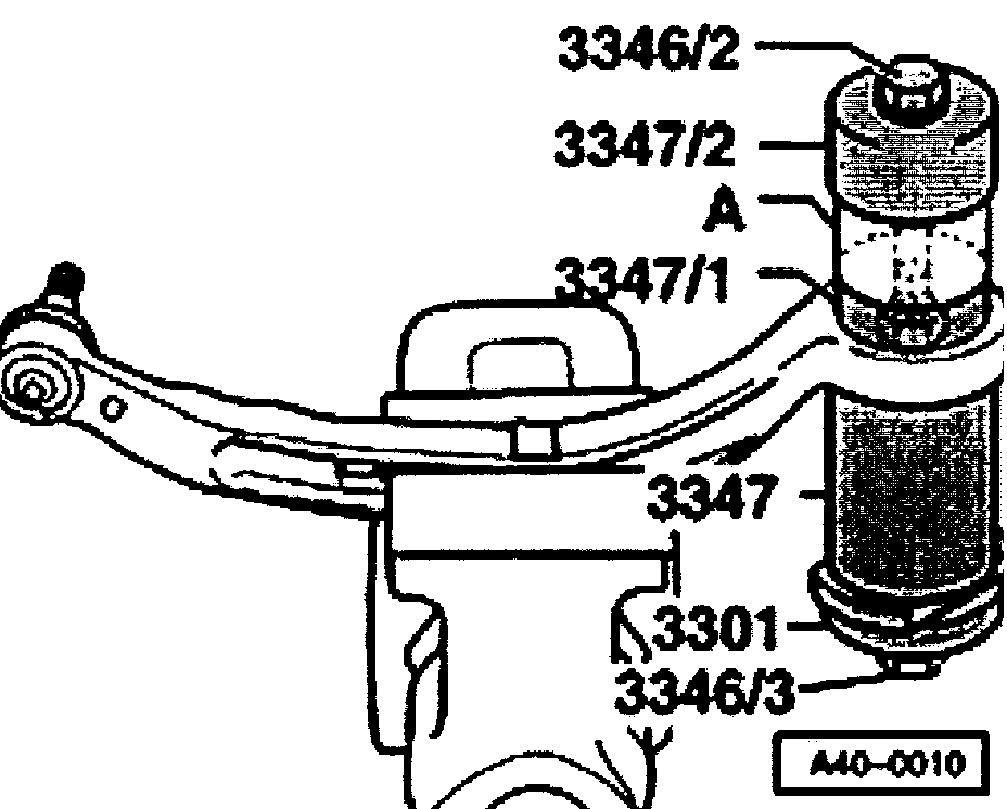
Pulling hydro-mounting out from guide link
Hydro-mounting installation position
The arrows on hydro-mounting -1- and groove -2- point toward the joint pin.
The maximum permissible deviation is ± 5°.
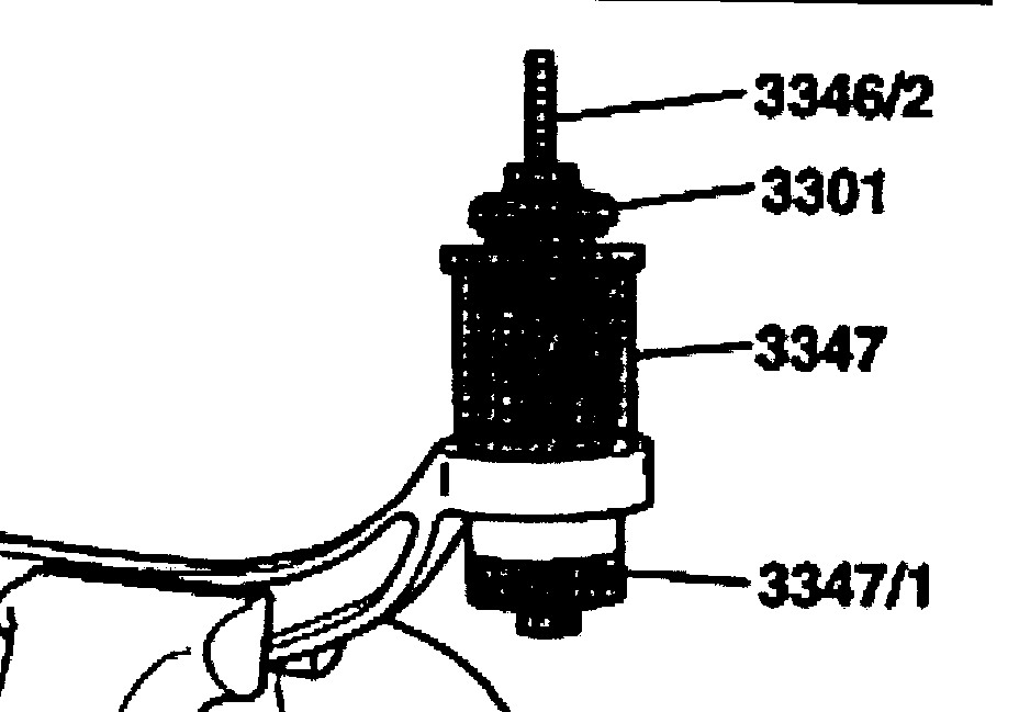
Pulling in hydro-mounting
- Insert hydro-mounting -A- in special tool -334712-.
- Tension sleeve -3347/1-, spindle-3346/2 and hex nut together.
- Pull in hydro-mounting -A- onto stop.
____________________________________
Let me know if this helps or if you have other questions.
Joe
Images (Click to enlarge)
Jan 3, 2019 at 5:07 PM