Computer or Electrical Issue

2002 JAGUAR XK8
184,000 MILES • 4.0L • V8 • 2WD • AUTOMATIC
Avatar
CANNON1349
  • CERTIFIED EXPERT
  • 861 POSTS
Hi,

This car came to me for a radiator replacement and another complaint was that it goes into "Engine Failsafe Mode" while driving, lowering power and acceleration. I drove it and confirmed this, along with messages like Gearbox Fault, ASC Off, Trac off, Brake Fluid Low (which it isn't), and Restricted Performance. I can reset by disconnecting the battery and then can drive it, and once it enters Failsafe Mode the instrument cluster dials drop to 0.

Here are the codes present:
P0442 - Evap leak (small)
P1797 (x2) - CAN TCM/ECM Circuit Malfunction
P1111 - System Pass
P0706 - TR Sensor Range / Performance
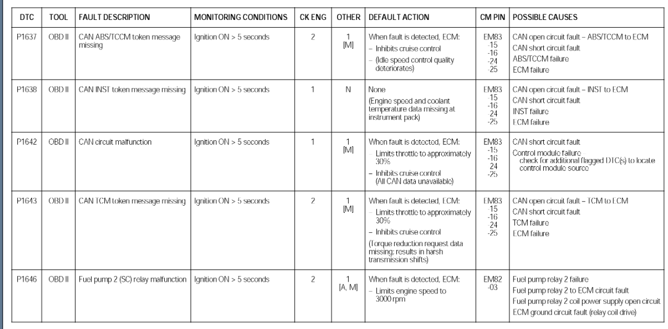
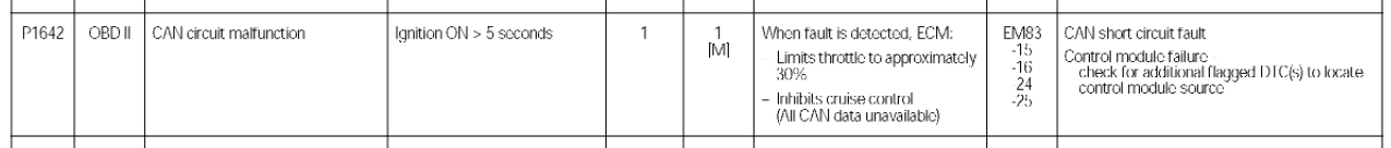
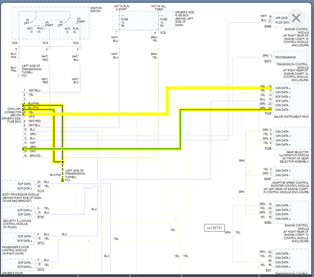
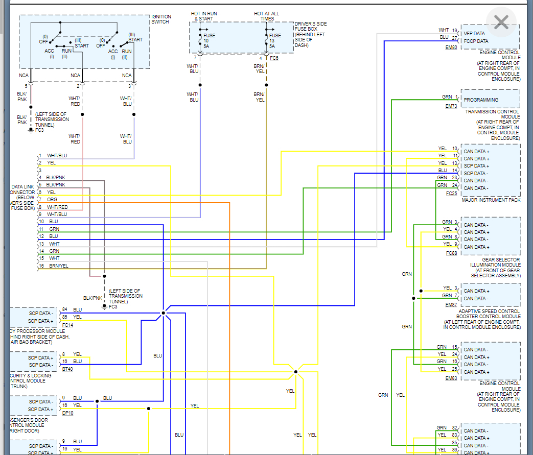
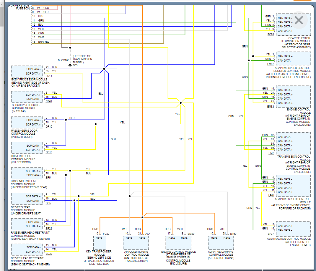
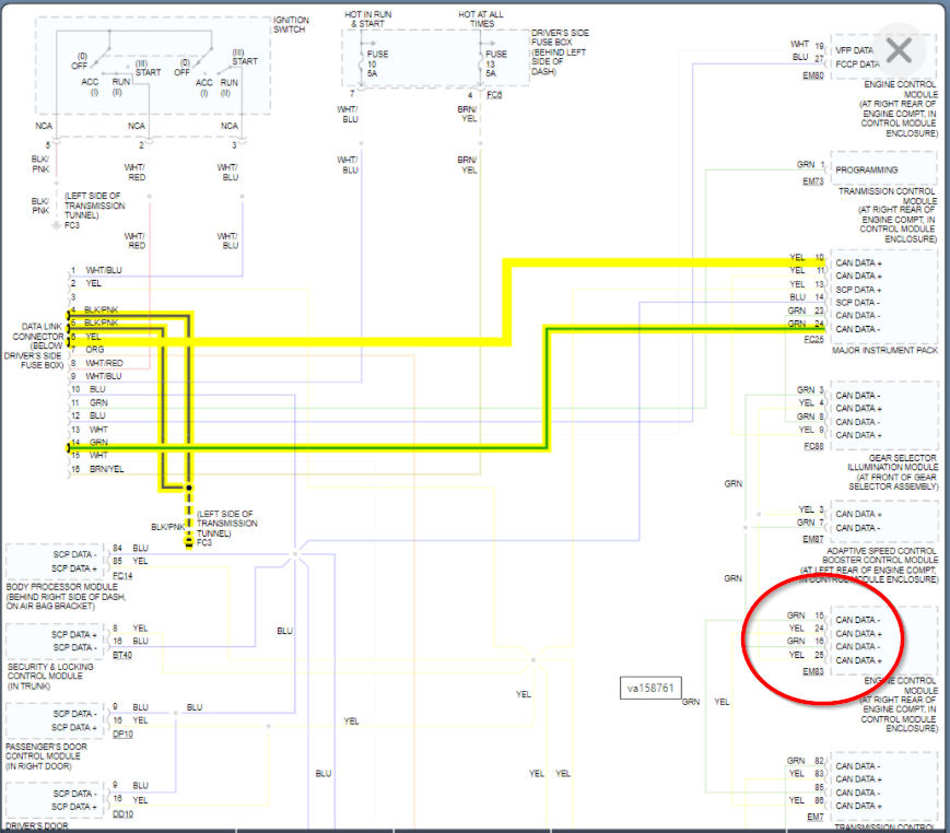
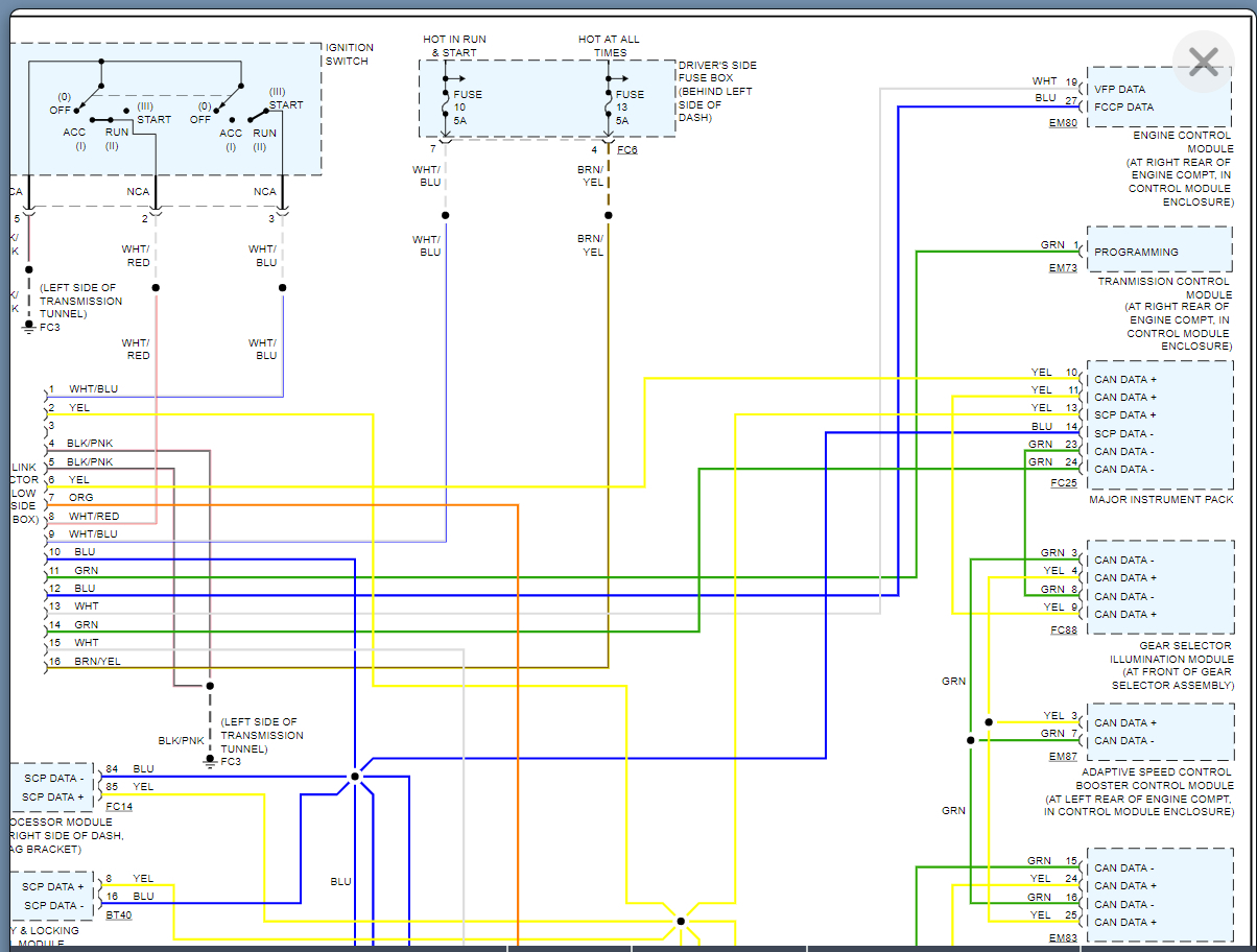
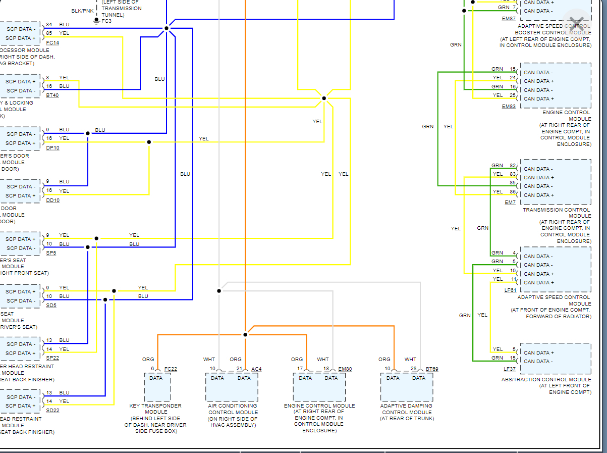
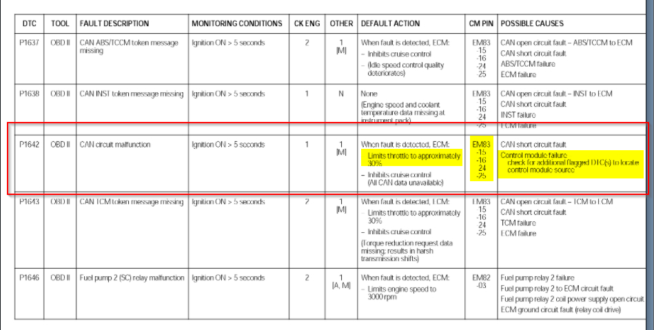
P1642 - CAN Link Circuit Malfunction
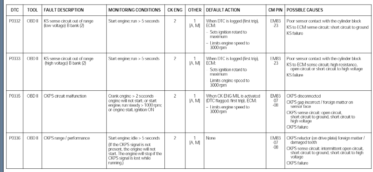
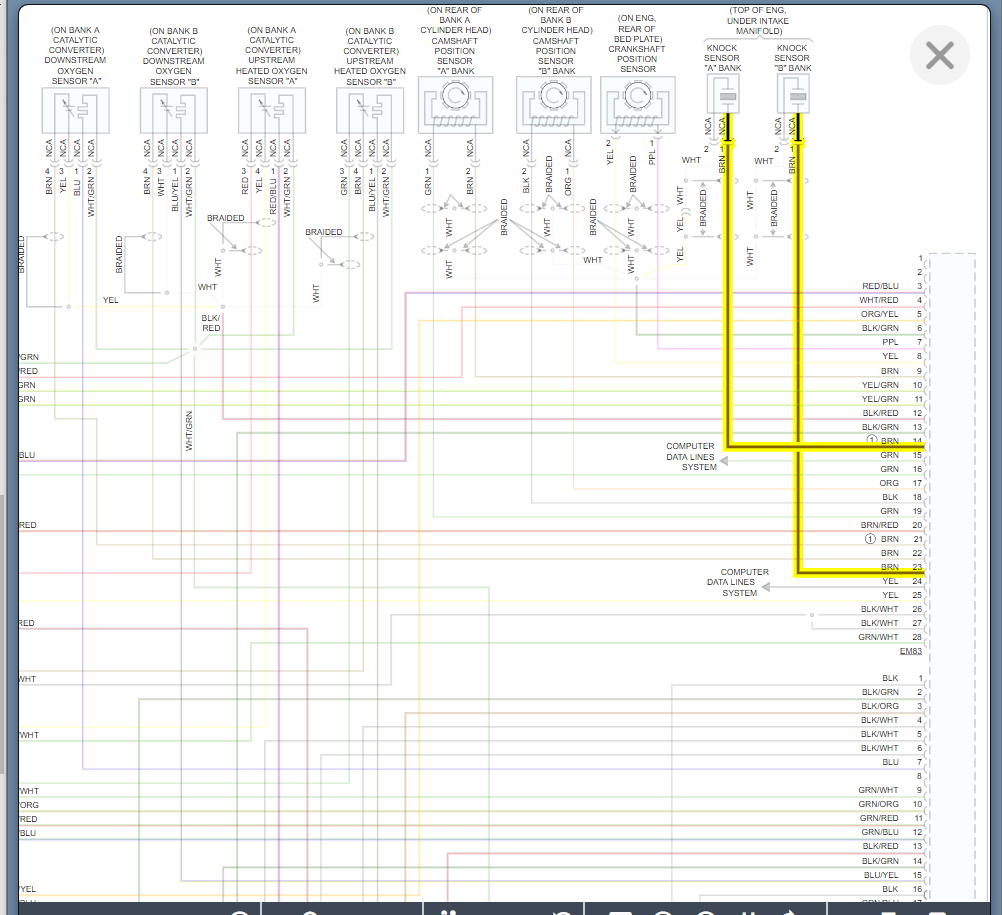
P0332 - Knock Sensor 2 circuit low
P0327 - Knock sensor 1 circuit low
P0174 - Too Lean Bank 2
P0171 - Too Lean Bank 1

I corrected P0706 with a new range sensor. It previously had trouble recognizing where the D position was.
Aug 23, 2021 at 5:30 PM
Advertisement
Avatar
KASEKENNY
  • CERTIFIED EXPERT
  • 18,907 POSTS
More than likely you have a PCM failure. Take a look at the testing for the P1642 and it basically says that the module that sets this DTC is at faulty.

I would suggest checking one of the other codes and making sure it leads to the PCM as well.

I would suggest using one of the knock sensor codes.

https://www.2carpros.com/articles/how-a-knock-sensor-works

However, the fact that you have a circuit low code on both points to the PCM as well.

It is highly unlikely that you have two knock sensors that are shorted.

Let's run through this info and let us know what you find or what questions you have.

Thanks
Aug 24, 2021 at 2:54 PM
Avatar
CANNON1349
  • CERTIFIED EXPERT
  • 861 POSTS
Well, I tried a replacement PCM and it did not change anything. So I put the old one back in. I also have codes regarding the TCM connection and ABS CAN connection malfunctions. I really have no idea what is happening with this thing. Maybe it's the instrument cluster? I know the clusters on these store information rather than just the PCM, but no clue on where to go from here.

Only other thing is that the battery is constantly needing to be jumped off. With the car running 14amps will be pumped to the battery but it almost never starts by itself.
Sep 3, 2021 at 3:56 PM
Advertisement
Avatar
KASEKENNY
  • CERTIFIED EXPERT
  • 18,907 POSTS
So changing the PCM resulted in the exact same codes?

Here is what I would suggest, put the new PCM in and start the vehicle even if you have to jump it and then scan for all the codes and let us know what they are.

If they are the exact same as above then you are correct that the PCM was not the issue even though that appears to be what it was.

If they are different but you still have the same issue of having to jump start the engine then the PCM was faulty but just wasn't causing the issue you are seeing.

Please let us know so we can be sure to be on the same page.

Thanks
Sep 4, 2021 at 6:44 PM
Avatar
CANNON1349
  • CERTIFIED EXPERT
  • 861 POSTS
For the record, I can't start the vehicle with the new ECM cause I can't program the VIN into it. It will just crank. But regardless, here are the codes with the new ECM:

P0455 (EVAP leak, gross leak)
P1000 (OBD readiness monitor not complete)
P1797 (CAN TCM/ECM Circuit Malfunction)
P1642 (CAN Link Circuit Malfunction)
P0332 (Knock Sensor 2 circuit low)

C1317 (???) Crankshaft position sensor circuit OR Fuel rail circuit?
B1712 (LF Door up switch short to ground)
C2000 (???)
Sep 5, 2021 at 11:22 AM
Avatar
KASEKENNY
  • CERTIFIED EXPERT
  • 18,907 POSTS
Okay. That is good info.

When you say you can't program the VIN into it, do you have the capability to program the VIN but just cannot communicate with it to do this? Or does you scan tool not have the ability?

The fact that the new PCM has the CAN codes shows we have a communication issue and most likely a wiring issue. So the new ECM once program may fix this but with the knock sensor code I am thinking you may have an issue with the harness.
Sep 6, 2021 at 6:34 AM
Avatar
CANNON1349
  • CERTIFIED EXPERT
  • 861 POSTS
I do not have the capability to program. I have been looking at some software for my PC as I have a very good USB/OBD2 dongle I use with Forscan.

I did notice the same knock sensor code. Do you suggest to follow these two wires back to the harness? There's barely any room in this engine bay.
Sep 6, 2021 at 6:37 AM
Avatar
KASEKENNY
  • CERTIFIED EXPERT
  • 18,907 POSTS
Correct. You have the same circuit codes but some of the others are gone. So you don't have to program the PCM for it to start monitoring all these circuits. So that tells you that the PCM had issues but the 3 circuit/CAN codes are your issue.

So the next step is to get a scan tool that can program this PCM even if you just borrow one from a friend. Because if you can program this and it starts and runs properly then these codes are not an issue or at least not causing the issue you are seeing with what started this post.

What I suspect is happening is there was an issue with the PCM causing the reduced power and if these communication codes prevent the PCM from being programmed then that is a different issue. However, we need to fix that to fix the first issue.

So if it were me, I would track down a scan tool before I start tracing wires because we don't know if this is preventing the programming of the PCM yet.
Sep 6, 2021 at 6:53 AM
Avatar
CANNON1349
  • CERTIFIED EXPERT
  • 861 POSTS
Well, even with the new PCM installed it still will give me the "engine failsafe mode" message after about 30 seconds or so. Which I think is automatic when one of these CAN codes shows up.
Sep 6, 2021 at 7:38 AM
Avatar
KASEKENNY
  • CERTIFIED EXPERT
  • 18,907 POSTS
Okay. If you are getting that message with out even starting the engine then you have a circuit issue.

I would go no further then the P1642, I attached the info below for it, where it states the CAN circuit is shorted or the control module is the issue. Due to the other PCM faults that would be the module effected but clearly that doesn't appear to be the issue.

Plus this code is the one causing the limited power as it states below.

What I would do is check the voltage at the DLC on pin 6 and ground. Then 14 and ground.

https://www.2carpros.com/articles/how-to-check-wiring

Let's see what the voltage is on both of these and start working through it. I suspect they are going to be wrong but we need to start at the beginning.
Sep 6, 2021 at 4:19 PM
Avatar
CANNON1349
  • CERTIFIED EXPERT
  • 861 POSTS
It says the DLC connector under driver side fuse box. Well, there is no fuse box on the driver's side. Except under the hood, and there is no connector there. Does it mean the OBD connector? If so, how are the terminals numbered? Also I attached a picture. It doesn't look too good. And also when I replaced the transmission range sensor the connector looked like this too.
Sep 9, 2021 at 10:00 AM
Avatar
CANNON1349
  • CERTIFIED EXPERT
  • 861 POSTS
As for the voltages, #14 to both grounds read at 1.84 Volts at both pins. #6 to both grounds fluctuated between 0-2.4volts.
Sep 9, 2021 at 11:45 AM
Avatar
KASEKENNY
  • CERTIFIED EXPERT
  • 18,907 POSTS
Oh man. That is an issue. It may not be the issue but that is the connector that we need to check those voltages and that is definitely an issue.

So these voltages need to add up to 5 volts. That is the way these modules communicate is the messages are coded based on the varying voltage. However, if one is 2.8 volts then the other is 2.2 volts.

They should not drop lower then 2 volts on the low side (pin 14) or higher then 3 volts on the high side (pin 6).

The fact that you have the low side at 1.84 volts shows it is being pulled to ground and the high side is the same thing. It should not be dropping to 0.

The fact that you have corrosion on this connector is where we need to start because if these pins are shorted to ground due to that corrosion then that is going to be the issue.

However, even if it is not the issue, it is something that will cause issues when you are trying to use the DLC.

Was this vehicle in a flood? I am not sure I have ever seen a DLC that corroded.
Sep 9, 2021 at 6:58 PM
Avatar
CANNON1349
  • CERTIFIED EXPERT
  • 861 POSTS
I replaced the connector. Now I am getting 1.84 volts at pin 14 and 3.02 volts at pin 6. I don't think this is any better. ha
Sep 11, 2021 at 3:31 PM
Avatar
KASEKENNY
  • CERTIFIED EXPERT
  • 18,907 POSTS
Unfortunately not. The next step is to continue monitoring this voltage (easier if you have two meters) and start unhooking modules that is on this network and see when the voltage returns to 2.3 volts and 2.7 volts.

When it does, you just disconnected the issue. It is either the connector, wiring, or module.

The fact that you already found corrosion that, means we need to be looking for that in these connectors as well.

I would start with the ECM. See the wiring diagram below for all these modules.
Sep 11, 2021 at 8:20 PM
Avatar
CANNON1349
  • CERTIFIED EXPERT
  • 861 POSTS
The two wires you had me check go straight to the instrument pack, according to this. How do I remove that to check? I have a hunch about it being such a short distance from this dlc connector.
Sep 12, 2021 at 5:47 AM
Avatar
KASEKENNY
  • CERTIFIED EXPERT
  • 18,907 POSTS
Correct. That is the cluster. I attached the info on that. Basically they treat this as a gateway or pass through module.

So they use this to access all the other modules from the DLC.

The only issue you are going to have, is you will have to access the voltage of this network from another source because you will lose your connection once this is out.

The voltage on this network is going to be the same anywhere you check. So if you disconnect the cluster then just check the voltage on the network to all their all modules. Not the wiring to the DLC. Looks like 13 and 14 are the pins to the rest of the network.

If the voltage returns normal on these wires then the cluster is the issue.
Sep 12, 2021 at 7:37 AM
Avatar
CANNON1349
  • CERTIFIED EXPERT
  • 861 POSTS
13 goes to the white wire at the ECM , but it says only one white and one blue wire, looking at it on the car the only setup where this exists is the fan that cools off the ECM. I get 12 volts whether or not the instrument cluster is plugged in or not.
Sep 12, 2021 at 12:06 PM
Avatar
KASEKENNY
  • CERTIFIED EXPERT
  • 18,907 POSTS
Okay. Those two wires, white and blue that go the ECM from the DLC are not part of this CAN system.

So just to be sure I was clear, you want to measure the voltage on any of the wires on that diagram that are labeled CAN data + or -.

So as you are unhooking these modules we need to know what the voltage is on these two wires. They are going to be the same no matter where you check it in the system as they are all spliced together onto the same circuits so we just need to know when they return to 2.3 and 2.7 volts (or close to it).
Sep 13, 2021 at 7:19 AM
Avatar
CANNON1349
  • CERTIFIED EXPERT
  • 861 POSTS
Just to be clear. These voltages should be read with the ignition on, or the car running, or just static?
Sep 13, 2021 at 5:25 PM
Avatar
KASEKENNY
  • CERTIFIED EXPERT
  • 18,907 POSTS
Great question. Just key on engine off is fine as that gets the bus awake and communicating.

Let me know what other questions you have as you work through it. Thanks
Sep 13, 2021 at 6:51 PM
Avatar
CANNON1349
  • CERTIFIED EXPERT
  • 861 POSTS
None of these wires add up. There's way more wires at the ECM than shown. And they aren't numbered either, I'm getting confused .
Sep 14, 2021 at 12:36 PM
Avatar
KASEKENNY
  • CERTIFIED EXPERT
  • 18,907 POSTS
Correct. This wiring diagram is only going to show wires that are part of this system.

So hopefully this connector view of the ECM will help with this.

These wires are on EM83 connector. Then they are numbers 15, 24, 16, 25.
Sep 14, 2021 at 4:49 PM
Avatar
CANNON1349
  • CERTIFIED EXPERT
  • 861 POSTS
On wires 15 and 24 on the EM83 connector i get 1volt. Unplugging modules didn't change this except unplugging the instrument cluster, which brought it down to 0.2 volts . On wires 16 and 25 I can't get any voltage. But I'm not sure if there is some operator error here. Also the transmission computer has some corrosion.. but nowhere near the level as that of the dlc connector. I attached photos.
Sep 16, 2021 at 11:07 AM
Avatar
KASEKENNY
  • CERTIFIED EXPERT
  • 18,907 POSTS
Okay. First any corrosion on these pins will cause shorts so that needs to be addressed. Was this vehicle in a flood? This is a lot of corrosion. If it was then we are going to have all sorts of connectors that look just like this.

As for the voltage readings. Those are not close to being correct. However, I just want to make sure you are checking these correctly. Are you checking the voltage from pin 15 to 24 and then 16 to 25? Or are you checking the voltage on pin 15 and the other lead on ground? Then 24 and ground, 16 and ground, 25 and ground?
Sep 16, 2021 at 12:38 PM
Avatar
CANNON1349
  • CERTIFIED EXPERT
  • 861 POSTS
I have to stick a small wire into the connectors so I get get my leads on it. Have one lead on 16 (-) and one lead on 25 (+) and same for the others.
Sep 16, 2021 at 12:41 PM
Avatar
KASEKENNY
  • CERTIFIED EXPERT
  • 18,907 POSTS
Okay. Sorry for the confusion. We need to check each of those wires to ground. So do the exact same thing except but the black lead of your meter on a good ground and leave it there, and then switch the red lead between each of those 4 wires.
Sep 16, 2021 at 12:43 PM
Avatar
CANNON1349
  • CERTIFIED EXPERT
  • 861 POSTS
Okay, so I have new information then. For my ground I used the strut tower nut/stud next to the ECM.

These are all voltages at the EM83 connector with the key ON.

EM83 connector, everything plugged in normally:
#16: 2.05V
#25: 3.04V
#15: 1.68V
#24: 3.28V

EM83 connector, Instrument cluster unplugged:
#16: 2.58V
#25: 2.35V
#15: 1.68V
#24: 3.29V

EM83 connector, transmission module unplugged:
#16: 2.06V
#25: 3.13V
#15: 0V
#24: 0V
Sep 16, 2021 at 1:03 PM
Avatar
KASEKENNY
  • CERTIFIED EXPERT
  • 18,907 POSTS
Okay. Let me try and breakdown what is happening. It will help if you look at the wiring diagram of this network while reading through this.

This CAN network is what we call daisy chain network. That means starting at the DLC the wires run to the cluster. Then from there they go to the gear selector, then the adaptive speed control and so on down the line.

So with everything connected, you have incorrect voltage on the entire network. You checked this at the ECM so before the ECM (modules above the ECM on the diagram) your voltages were close but not correct. This would indicate an issue in one of these modules or wiring.

However, when you unplug the cluster, which is at the end of this part of the chain, your voltage on these pins (16 and 25) return to perfectly normal.

However, the modules that are part of the chain below the ECM still have incorrect voltage. This means you still have an issue there. Removing the TCM breaks the chain and causes this to have no voltage on that portion.

This is very odd behavior. So I think I am getting more convinced that this was a flood vehicle and you are going to find corrosion in a lot of connectors.

In other words, I don't think you are going to find one thing, replace it and fix all these issues.

You already found a lot of corrosion on the DLC which I have not seen on vehicles that were not submerged in water but you now have multiple places that have considerable amounts of corrosion.

At this point, I would suggest starting with inspecting connectors related to all these modules and any corrosion you find, fix it by replacing connectors or modules and then retest the system. If it is not fixed, check the voltage again to see if is closer to the 2.3 and 2.7 as I suspect the more you find and fix it will slowly change that voltage.

If unhooking the cluster gets that portion of the voltage to return to normal the we have an issue with the cluster as well.
Sep 16, 2021 at 1:42 PM
Avatar
CANNON1349
  • CERTIFIED EXPERT
  • 861 POSTS
The only thing I haven't checked is the adaptive speed control module and the module on the top that says "programming" for the trans. I can't find these. But I've only seen corrosion at the TCM and at the harness for the transmission range sensor, so far. So at least we know the cluster has an issue.
Sep 16, 2021 at 1:51 PM
Avatar
CANNON1349
  • CERTIFIED EXPERT
  • 861 POSTS
So I decided to plug everything back in and test the TCM connector. Here's what I found:

#82: 2.48V
#83: 2.48V
#85: 2.38V
#86: 2.62V

You said the voltage should be the same throughout the system. So if the voltage looks correct here and wrong when it's connected to the TCM, is the TCM an issue? And being later in the chain than the cluster, possibly both the cluster and the TCM have an issue?
Sep 16, 2021 at 3:04 PM
Avatar
KASEKENNY
  • CERTIFIED EXPERT
  • 18,907 POSTS
Sorry. Maybe I misunderstood. If this was the voltage with everything hooked up except for the TCM then you are correct that the TCM appears to be the issue.

Great job doing that. We would have gone down the wrong path if you would not have done that.
Sep 16, 2021 at 6:46 PM
Avatar
CANNON1349
  • CERTIFIED EXPERT
  • 861 POSTS
Yes that's the voltage with everything hooked up, except the TCM. That is the voltage at the TCM connector. So then, would that mean both the instrument cluster and TCM are bad?
Sep 16, 2021 at 6:48 PM
Avatar
KASEKENNY
  • CERTIFIED EXPERT
  • 18,907 POSTS
It does not mean that the cluster is faulty as well. If everything is hooked up and you have correct voltage then what is unhooked is all that is wrong.

The only thing that gives me pause is that when your two voltages are exactly the same it points to the fact that the wires are shorted together.

So try unplugging the cluster as well as the TCM and see if the two voltages that are 2.48 split a little more and that will point to a cluster issue.

If not, I would go with the TCM or a wiring issue with the TCM connector but this acts like a module.
Sep 16, 2021 at 7:14 PM
Avatar
CANNON1349
  • CERTIFIED EXPERT
  • 861 POSTS
I went to double check the TCM connector. Maybe I did something wrong previously. Here are the values right now:

#86: 2.61V
#85: 2.38V
#83: 3.11V
#82: 1.90V
Sep 17, 2021 at 8:09 AM
Avatar
KASEKENNY
  • CERTIFIED EXPERT
  • 18,907 POSTS
Okay. Just to confirm, you have everything except the TCM plugged in and these are your voltage?

If that is the case, your TCM is an issue. What is not clear on this vehicle is if the 3.11 and 1.90 volts is close enough for it to communicated.

What I would do at this point, is replace the TCM and then plug everything back in and see if you get the P1642 code to return. I suspect all that will be repaired which will fix the majority of these issues if not all of them.
Sep 17, 2021 at 11:09 AM
Avatar
CANNON1349
  • CERTIFIED EXPERT
  • 861 POSTS
My assumption is that the 3.11 and 1.90 will be corrected once the system is all connected with a functional module.
Sep 17, 2021 at 11:29 AM
Avatar
KASEKENNY
  • CERTIFIED EXPERT
  • 18,907 POSTS
That is possible. However, the way this system works is these modules send coded messages across these two wires. The way that it has to do this is by having this voltage spread by the half voltage.

So if the spread is too much or two little the message comes in corrupted so that module doesn't know what it was.

So this amount could be just fine but I agree, we know that TCM is an issue so we need to start with that.

Let us know what happens. Thanks
Sep 17, 2021 at 3:29 PM
Avatar
CANNON1349
  • CERTIFIED EXPERT
  • 861 POSTS
Sorry for the delay. Had to wait for the part and do some other unrelated repairs. The 17 codes so far have gone away. And the car does drive now and no failsafe engine mode. So far so good. I'm patting myself on the back on this one.
Sep 29, 2021 at 5:33 AM
Avatar
KASEKENNY
  • CERTIFIED EXPERT
  • 18,907 POSTS
Pat yourself on the back again because you deserve it. Thanks for the update and sticking with us to let us know what happens.

Thanks again for using 2CarPros.
Sep 29, 2021 at 4:05 PM