Naser,
All of the codes are related to the MAP sensor except the 452. It's tied into the EVAP pressure switch which can be an electrical issue or even a gas cap.
Have you checked the MAP sensor? Since three of the codes are related to it, that is where I would start. Here is the diagnostics for testing the sensor:
___________________________________________
2013 Dodge Dart L4-1.4L Turbo
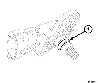
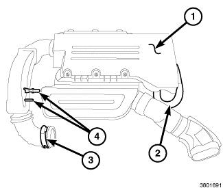
Checking The MAP Sensor Operation
Vehicle Power-train Management Sensors and Switches - Power-train Management Sensors and Switches - Computers and Control Systems Manifold Pressure/Vacuum Sensor Testing and Inspection Component Tests and General Diagnostics Checking The MAP Sensor Operation
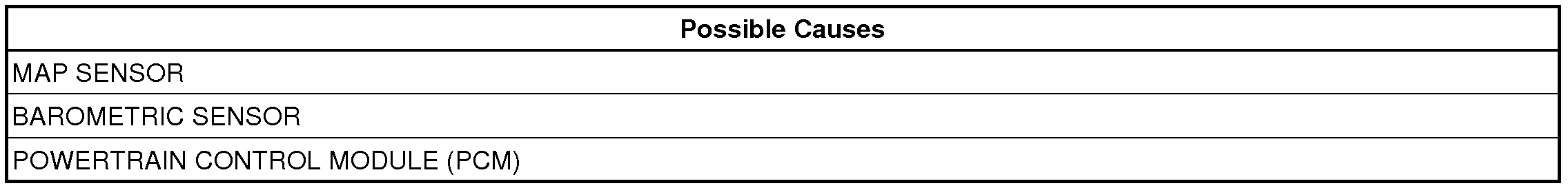
CHECKING THE MAP SENSOR OPERATION
CHECKING THE MAP SENSOR OPERATION
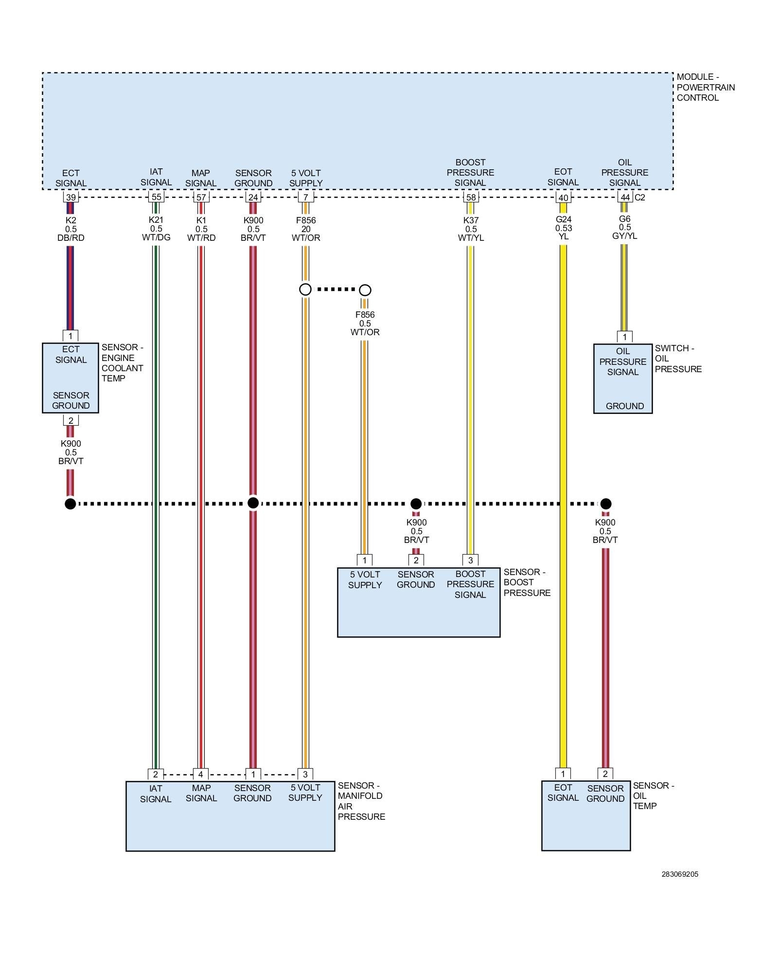
For a complete wiring diagram, refer to the Wiring Information.
Diagnostic Test
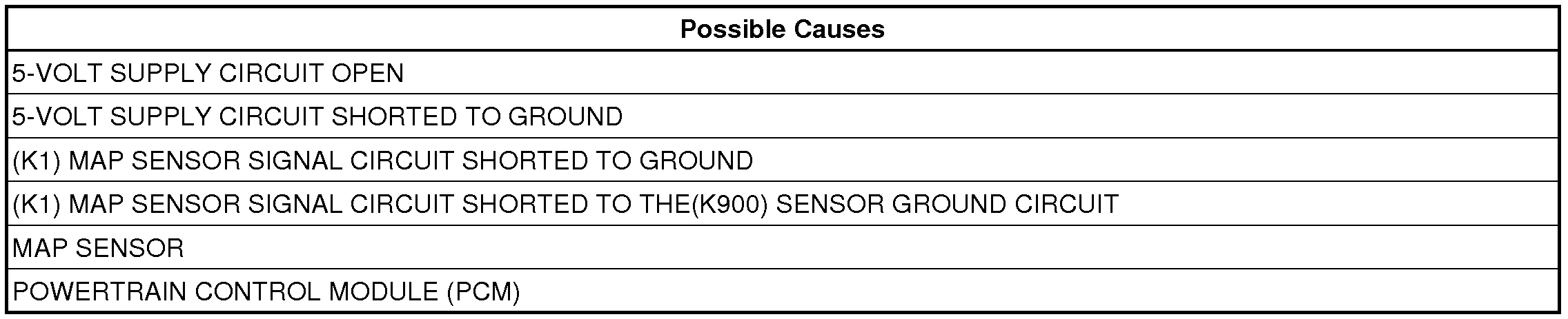
1. MAP SENSOR WIRING OR CONNECTORS
NOTE: Diagnose and repair any MAP Sensor circuit DTCs before proceeding with this test.
NOTE: Diagnose and repair any sensor supply or system voltage DTCs before proceeding with this test.
1. Turn the ignition off.
2. Using the wiring diagram/schematic as a guide, inspect the wiring and connectors between the MAP Sensor and the PCM.
3. Look for any chafed, pierced, pinched, or partially broken wires.
4. Look for broken, bent, pushed out or corroded terminals.
5. Turn the ignition on.
6. Monitor the scan tool data relative to the sensor and wiggle test the wiring and connectors.
7. Look for the data to change or for a DTC to set during the wiggle test. If necessary, check each sensor circuit for high resistance or a shorted condition.
Were any problems found?
Yes
- Repair as necessary.
- Perform the Power-train Verification Test. See: A L L Diagnostic Trouble Codes ( DTC ) > Verification Tests > Power-train Verification Test.
No
- Go To 2
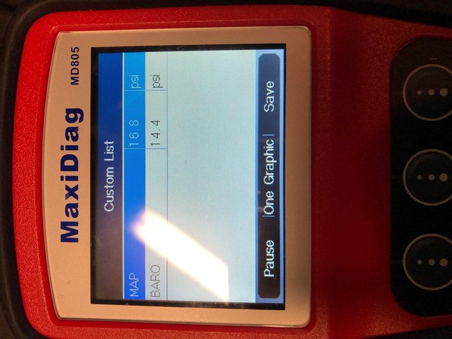
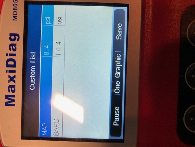
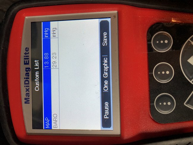
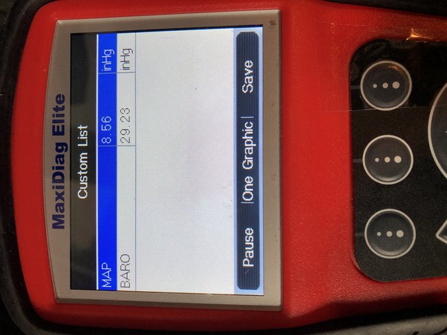
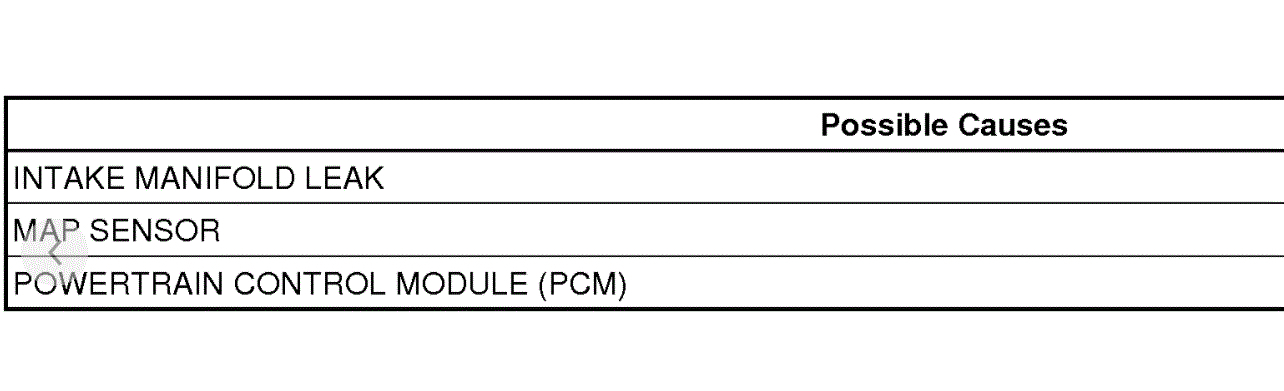
2. MAP VACUUM/BAROMETRIC PRESSURE
1. With a scan tool, read the Barometric Pressure.
NOTE: The Barometric Pressure should be approximately equal to the actual barometric pressure. If necessary, compare the Barometric Pressure value of the tested vehicle to the value of a known good vehicle of a similar make and model.
2. Connect a vacuum gauge to a manifold vacuum source.
3. Start the engine.
NOTE: If the engine will not idle, maintain a constant RPM above idle.
WARNING:
When the engine is operating, do not stand in direct line with the fan. Do not put your hands near the pulleys, belts, or fan. Do not wear loose clothing. Failure to follow these instructions can result in possible serious or fatal injury.
4. With the scan tool, read the MAP Sensor value.
NOTE: The scan tool reading for MAP vacuum should be within 1" of the vacuum gauge reading.
Were any problems found?
Yes
- Go To 4
No
- Go To 3
3. CHECK THE MAP SENSOR VOLTAGE
1. With the scan tool, monitor the MAP Sensor signal voltage.
2. With the engine idling in neutral or park, snap the throttle.
NOTE: The MAP Sensor signal voltage should change from below 2.0 volts at idle to above 3.5 volts at wide open throttle.
Were any problems found?
Yes
- Go To 4
No
- Test complete.
4. CHECK THE 5-VOLT SUPPLY CIRCUIT FOR HIGH RESISTANCE
1. Turn the ignition off.
2. Using a voltmeter, perform a voltage drop test on the MAP Sensor 5-Volt Supply circuit between the MAP Sensor harness connector and the PCM harness connector.Make sure the voltmeter leads are connected so that positive polarity is displayed on the voltmeter.
WARNING:
When the engine is operating, do not stand in direct line with the fan. Do not put your hands near the pulleys, belts, or fan. Do not wear loose clothing. Failure to follow these instructions can result in possible serious or fatal injury.
3. Start the engine.
Is the voltage reading below 0.1 volt?
Yes
- Go To 5
No
- Repair the 5-Volt Supply circuit for excessive resistance.
- Perform the POWER-TRAIN VERIFICATION TEST. See: A L L Diagnostic Trouble Codes ( DTC ) > Verification Tests > Power-train Verification Test.
5. CHECK THE MAP SENSOR SIGNAL CIRCUIT FOR HIGH RESISTANCE
1. Turn the ignition off.
2. Using a voltmeter, perform a voltage drop test on the MAP Sensor Signal circuit between the MAP Sensor harness connector and the PCM harness connector.Make sure the voltmeter leads are connected so that positive polarity is displayed on the voltmeter.
WARNING:
When the engine is operating, do not stand in direct line with the fan. Do not put your hands near the pulleys, belts, or fan. Do not wear loose clothing. Failure to follow these instructions can result in possible serious or fatal injury.
3. Start the engine.
Is the voltage reading below 0.1 volt?
Yes
- Go To 6
No
- Repair the MAP Sensor Signal circuit for excessive resistance.
- Perform the POWER-TRAIN VERIFICATION TEST. See: A L L Diagnostic Trouble Codes ( DTC ) > Verification Tests > Powertrain Verification Test.
6. CHECK THE MAP SENSOR GROUND CIRCUIT FOR HIGH RESISTANCE
1. Turn the ignition off.
2. Using a voltmeter, perform a voltage drop test on the MAP Sensor Ground circuit between the MAP Sensor harness connector and the PCM harness connector.Make sure the voltmeter leads are connected so that positive polarity is displayed on the voltmeter.
WARNING:
When the engine is operating, do not stand in direct line with the fan. Do not put your hands near the pulleys, belts, or fan. Do not wear loose clothing. Failure to follow these instructions can result in possible serious or fatal injury.
3. Start the engine.
Is the voltage below 0.1 volt?
Yes
- Go To 7
No
- Repair the MAP Sensor Ground circuit for excessive resistance.
- Perform the Power-train Verification Test. See: A L L Diagnostic Trouble Codes ( DTC ) > Verification Tests > Power-train Verification Test
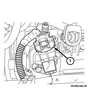
7. MAP SENSOR
1. Using the wiring diagram/schematic as a guide, inspect the wiring and connectors between the MAP Sensor and the Power-train Control Module (PCM).
2. Look for any chafed, pierced, pinched, or partially broken wires.
3. Look for broken, bent, pushed out or corroded terminals.
4. Perform any Technical Service Bulletins that may apply.
Were any problems found?
Yes
- Repair as necessary.
- Perform the Power-train Verification Test. See: A L L Diagnostic Trouble Codes ( DTC ) > Verification Tests > Power-train Verification Test
No
- Replace the MAP Sensor. See: Manifold Pressure/Vacuum Sensor > Removal and Replacement.
- Perform the Power-train Verification Test. See: A L L Diagnostic Trouble Codes ( DTC ) > Verification Tests > Power-train Verification Test.
_____________________________________
Let me know what you find. Also, note that since you indicated turbo, the information is specific to the 1.4L turbo.
Joe
Aug 22, 2020 at 9:02 PM