Welcome back:
That is surely the cause of the cyl 4 misfire. That isn't enough compression to fire the cylinder.
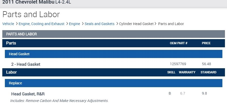
I attached a pic below. It is parts and labor for a head gasket replacement. The labor listed is for removing and replacing the head.
Here are the directions for replacing a head gasket. Keep in mind, it could be a valve issue or something different.
2011 Chevrolet Malibu L4-2.4L
15. Cylinder Head Removal
Vehicle Engine, Cooling and Exhaust Engine Service and Repair Overhaul Unit Repair 2011 Malibu 2.4L 15. Cylinder Head Removal
15. CYLINDER HEAD REMOVAL
Cylinder Head Removal (LAP, LAT, LE5, LE8, LE9)
Special Tools
EN-38188 - Cylinder Head Broken Bolt Extractor Kit
For equivalent regional tools, refer to Special Tools (See: Engine > Electrical / Mechanical Repair > Special Tools).
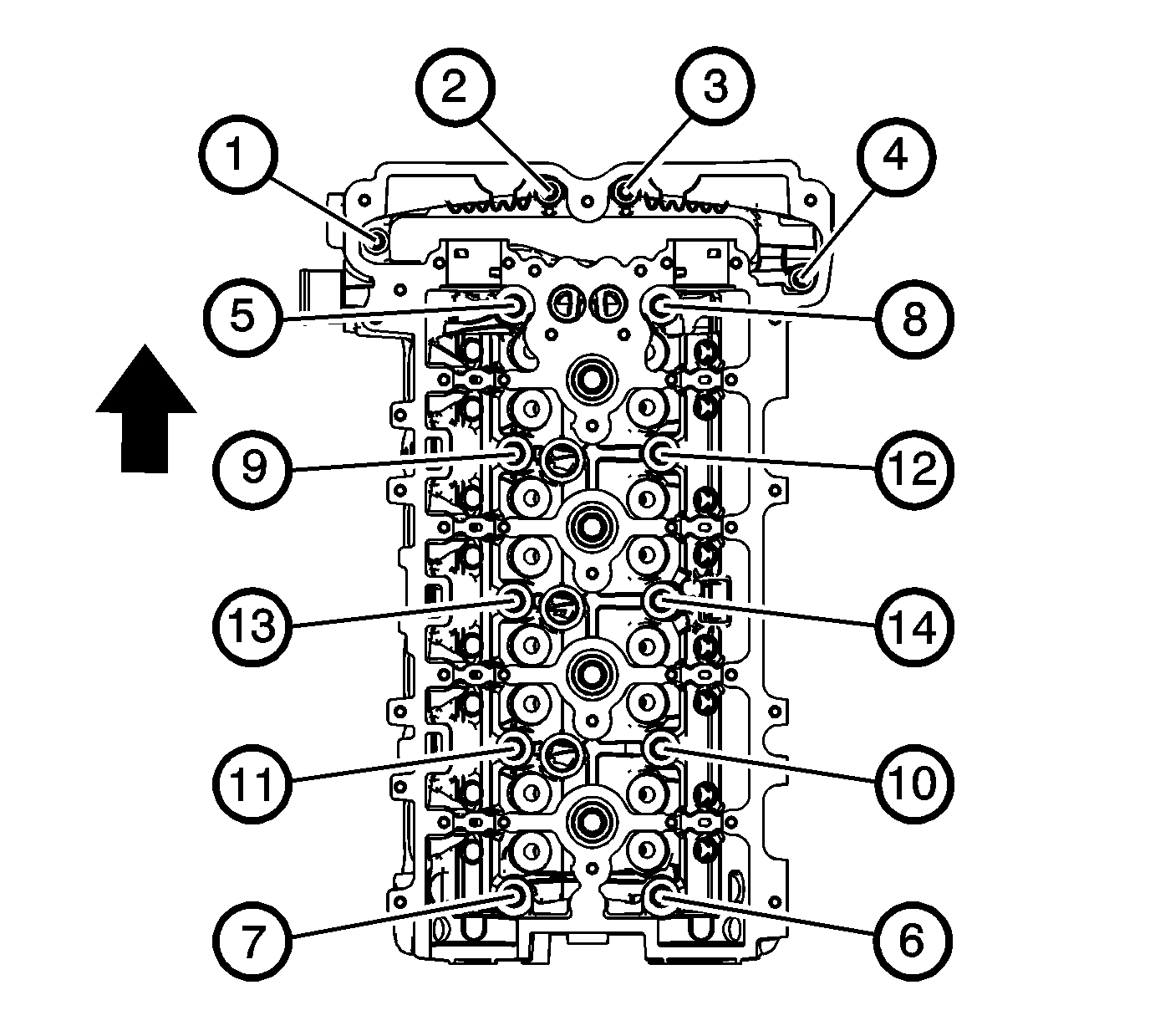
pic 2
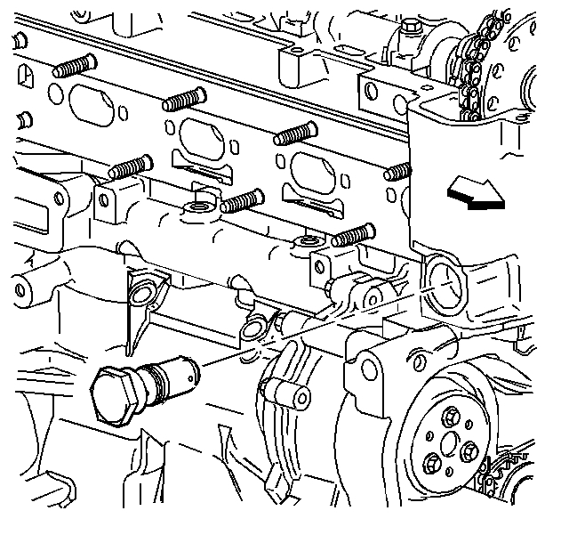
1. Remove the cylinder head to the block bolts in sequence.
Discard the bolts.
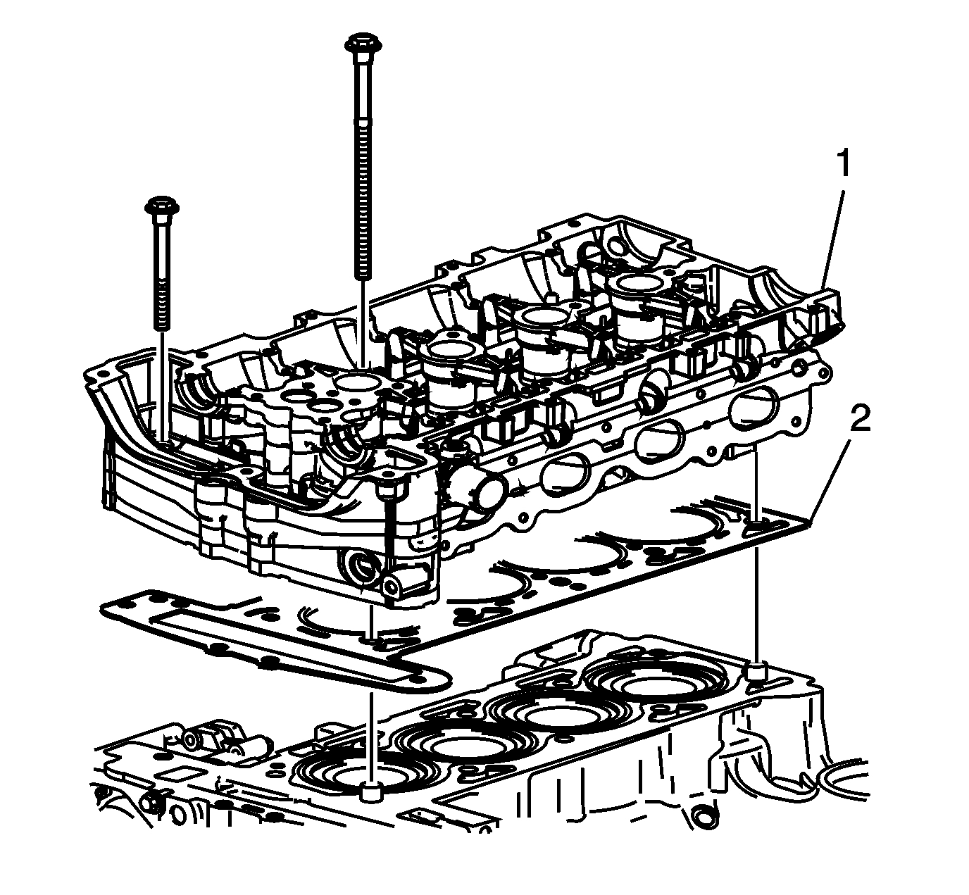
pic 3
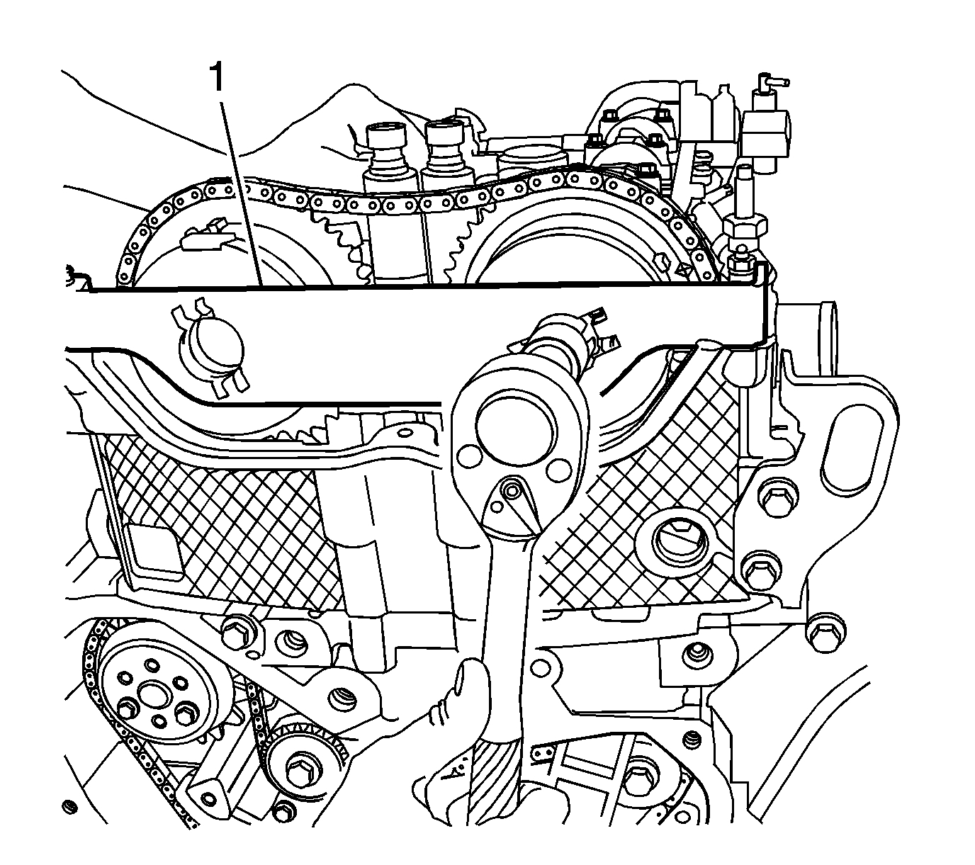
Caution: In order to prevent damage to the valves and injectors during cylinder head removal, set the cylinder head on blocks.
2. Remove the cylinder head (1).
3. Remove the cylinder head gasket (2).
4. Clean all of the gasket surfaces.
5. Use the following procedures when cleaning the cylinder head and cylinder block surfaces:
* Use a razor blade gasket scraper to clean the cylinder head and cylinder block gasket surfaces. Do not scratch or gouge any surface.
Note: Do not use any other method or technique to clean these gasket surfaces.
* Use a new razor blade for each cylinder head and cylinder block.
Note: Be careful not to gouge or scratch the gasket surfaces. Do not gouge or scrape the combustion chamber surfaces. The feel of the gasket surface is important, not the appearance. There will be indentations from the gasket left in the cylinder head after all of the gasket material is removed. These small indentations will be filled in by the new gasket.
* Hold the razor blade as parallel to the gasket surface as possible.
Note: Do not use a tap to clean the cylinder head bolt holes.
6. Clean the old sealer/lube and dirt from the bolt holes.
7. Clean the bolt holes with a nylon bristle brush.
Warning
Wear safety glasses to avoid injury when using compressed air or any cleaning solvent. Bodily injury may occur if fumes are inhaled or if skin is exposed to chemicals.
8. When cleaning the cylinder head bolt holes use a suitable commercial spray liquid solvent and compressed air from an extended-tip blow gun to reach the bottom of the holes.
9. Remove any broken long cylinder head bolts using the EN-38188 - extractor kit.
___________________________________
2011 Chevrolet Malibu L4-2.4L
51. Cylinder Head Installation
Vehicle Engine, Cooling and Exhaust Engine Service and Repair Overhaul Unit Repair 2011 Malibu 2.4L 51. Cylinder Head Installation
51. CYLINDER HEAD INSTALLATION
Cylinder Head Installation (LAP, LAT, LE5, LE8, LE9)
Special Tools
EN 45059 - Angle Meter
For equivalent regional tools, refer to Special Tools (See: Engine > Electrical / Mechanical Repair > Special Tools).
pic 4
Note: Do not use any sealing material.
1. Install the cylinder head gasket (2) to the block.
2. Install the cylinder head (1).
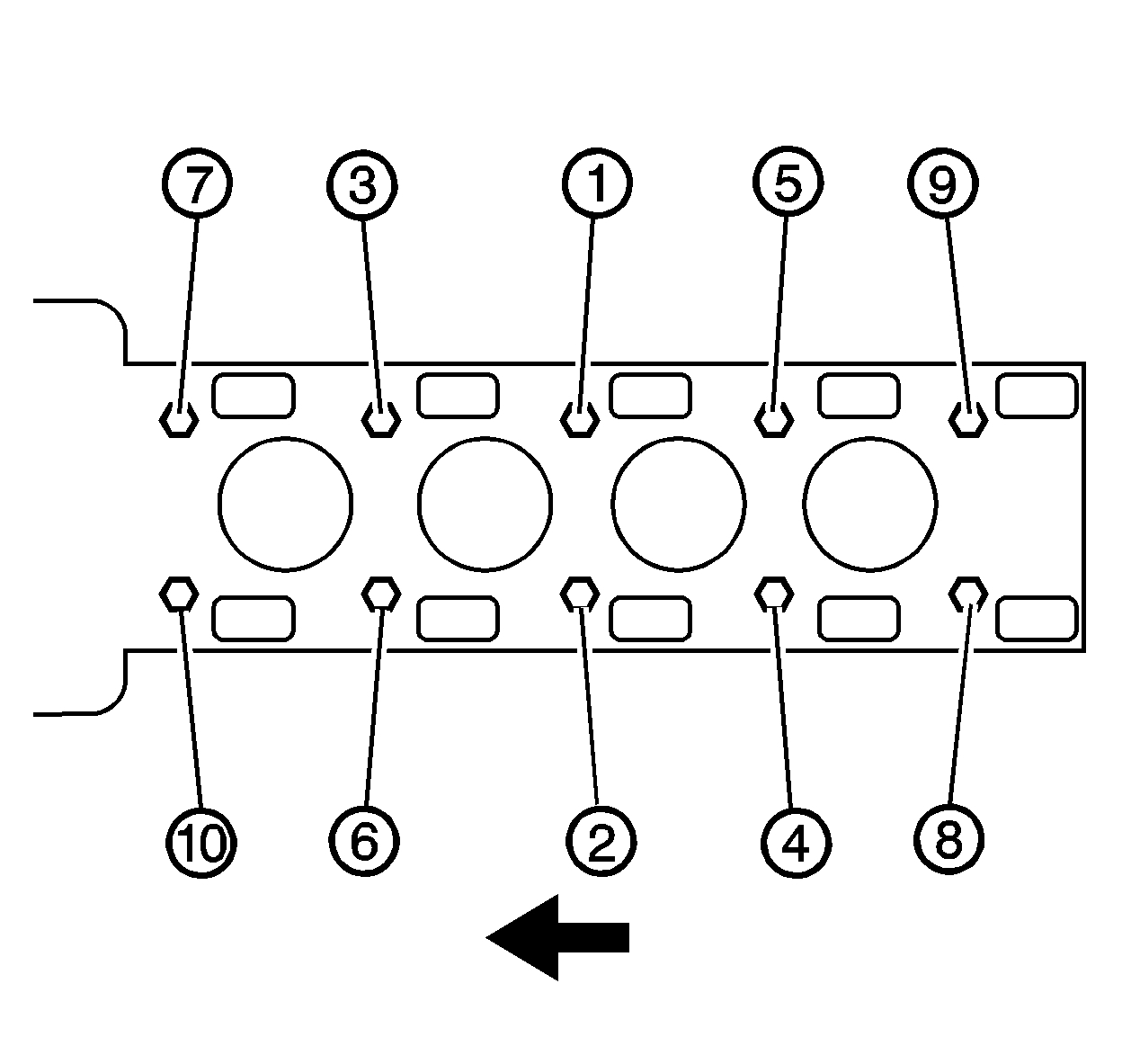
pic 5
Caution: Refer to Fastener Caution (See: Vehicle > Vehicle Damage Warnings > Fastener Caution).
Note: Always use new cylinder head bolts.
3. Install and tighten the cylinder head bolts in sequence.
* Tighten the bolts to 30 Nm (22 lb ft).
* Using the EN 45059 - meter , tighten the bolts an additional 155 degrees in sequence.
pic 6
4. Install the front cylinder head bolts (1) and tighten to 35 Nm (26 lb ft).
________________________________________________
The most difficult part of the job is related to the timing chain removal and replacement. The chain needs removed from the cams for head removal. Here are the extensive directions. All remaining pics correlate with the directions.
________________________________________________
2011 Chevrolet Malibu L4-2.4L
Camshaft Timing Chain, Sprocket, and Tensioner Replacement
Vehicle Engine, Cooling and Exhaust Engine Timing Components Timing Chain Service and Repair Removal and Replacement Camshaft Timing Chain, Sprocket, and Tensioner Replacement
CAMSHAFT TIMING CHAIN, SPROCKET, AND TENSIONER REPLACEMENT
Camshaft Timing Chain, Sprocket, and Tensioner Replacement
Special Tools
* EN-45027 - Tensioner Tool
* EN-45059 - Angle Meter
For equivalent regional tools, refer to Special Tools (See: Engine > Electrical / Mechanical Repair > Special Tools).
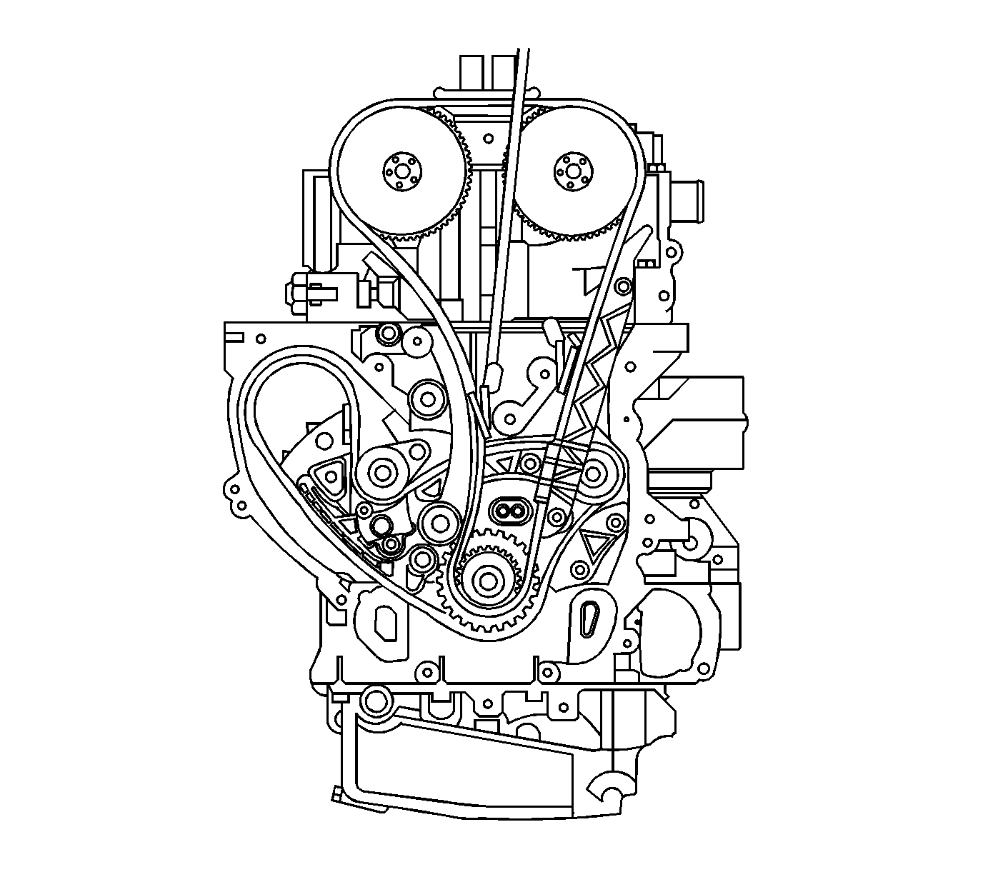
Removal Procedure
imageOpen In New TabZoom/Print
1. Remove the number 1 cylinder spark plug. Refer to Spark Plug Replacement (See: Spark Plug > Removal and Replacement).
2. Rotate the crankshaft in the engine rotational direction clockwise, until the number 1 piston is at top dead center (TDC) on the exhaust stroke.
3. Remove the camshaft cover. Refer to Camshaft Cover Replacement (See: Valve Cover > Removal and Replacement > Camshaft Cover Replacement).
4. Remove the engine front cover. Refer to Engine Front Cover Replacement (See: Timing Cover > Removal and Replacement).
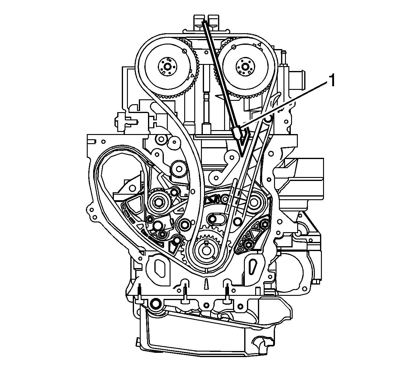
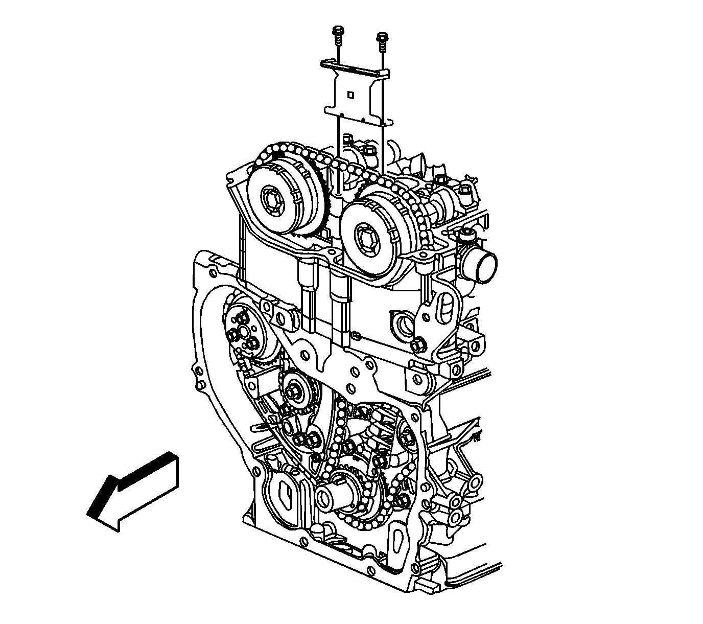
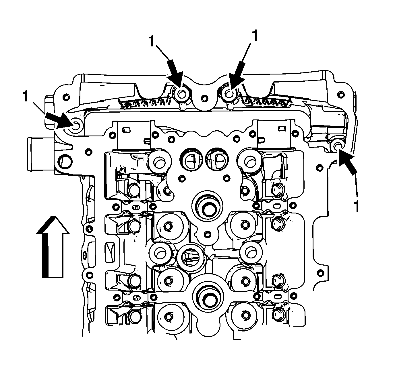
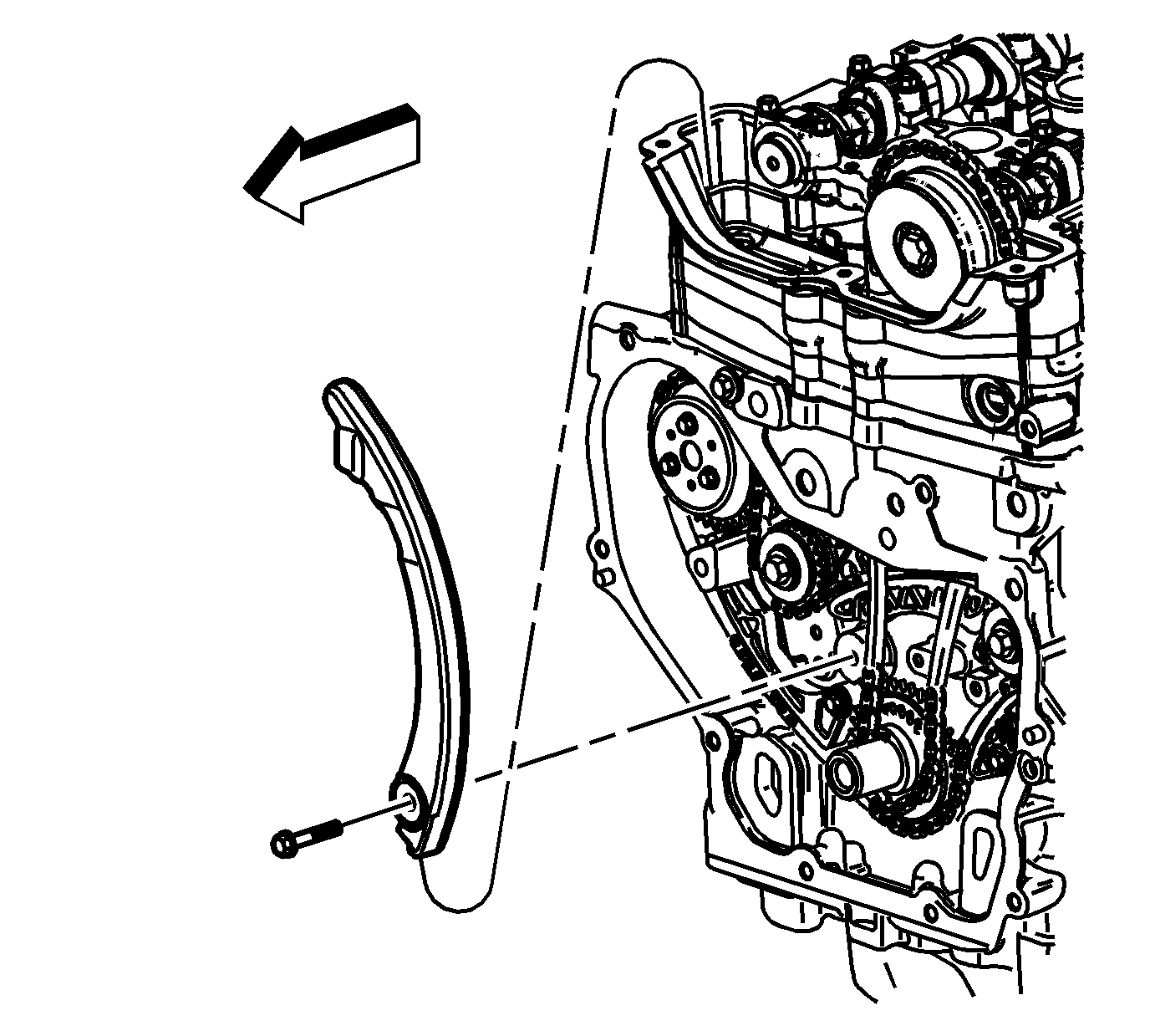
5. Remove the upper timing chain guide bolts and guide.
pic 7
Note: The timing chain tensioner must be removed to unload chain tension before the timing chain is removed. If it is not, the timing chain will become cocked and it will be difficult to remove.
6. Remove the timing chain tensioner.
pic 8
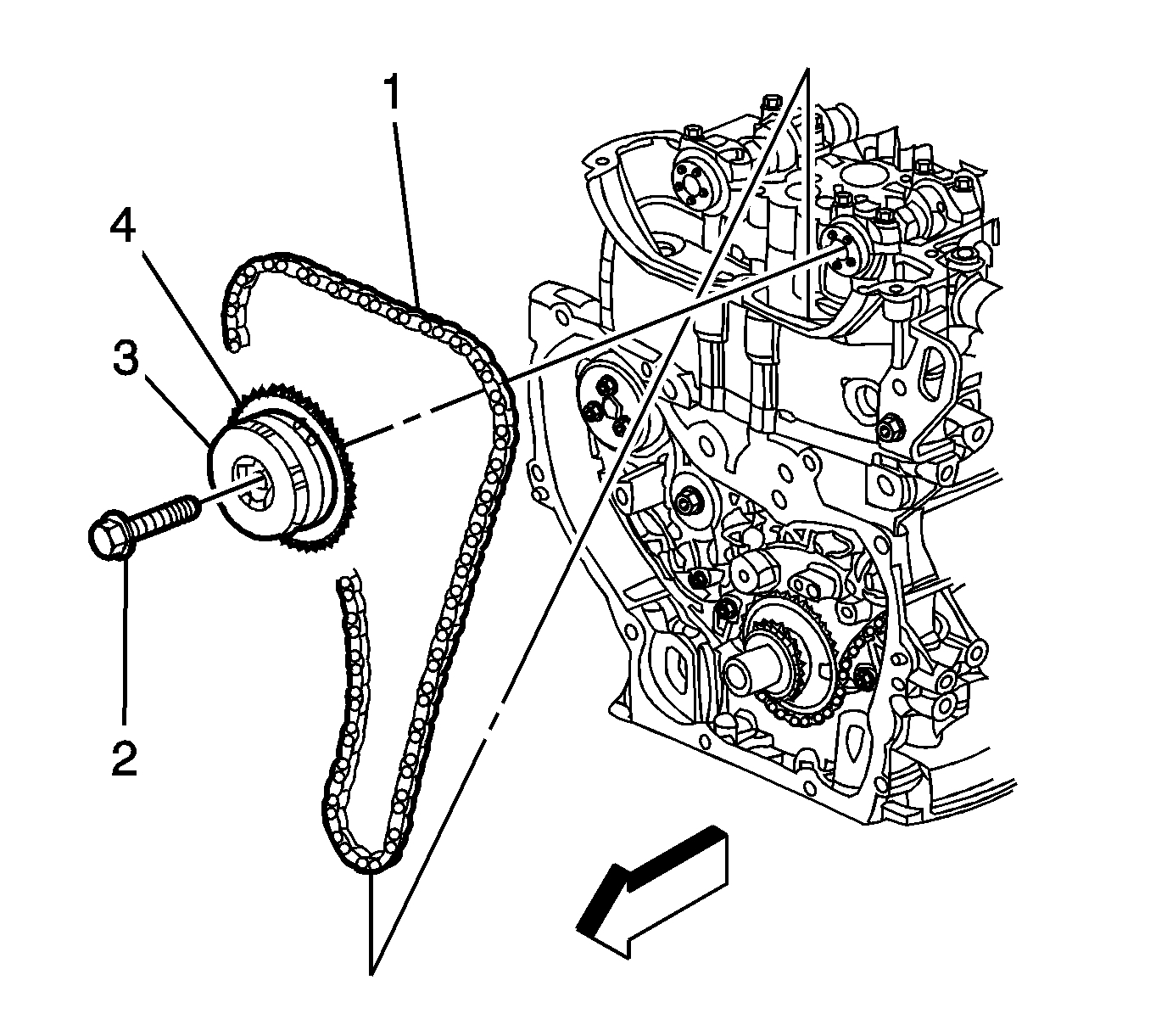
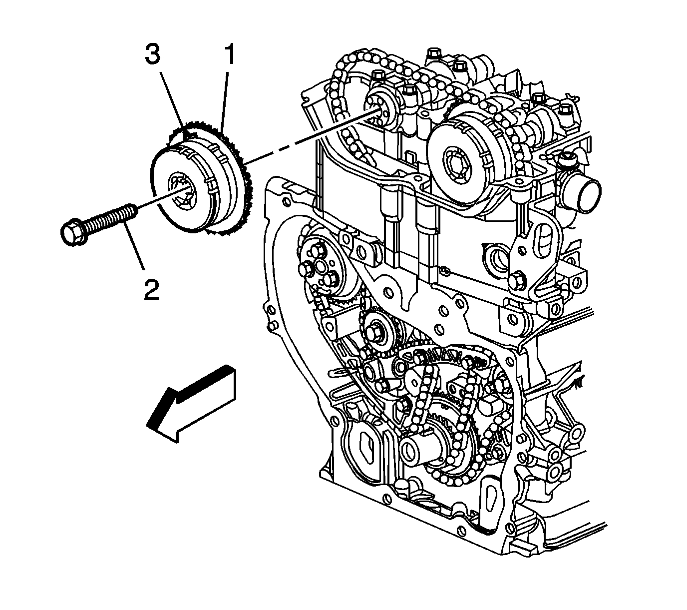
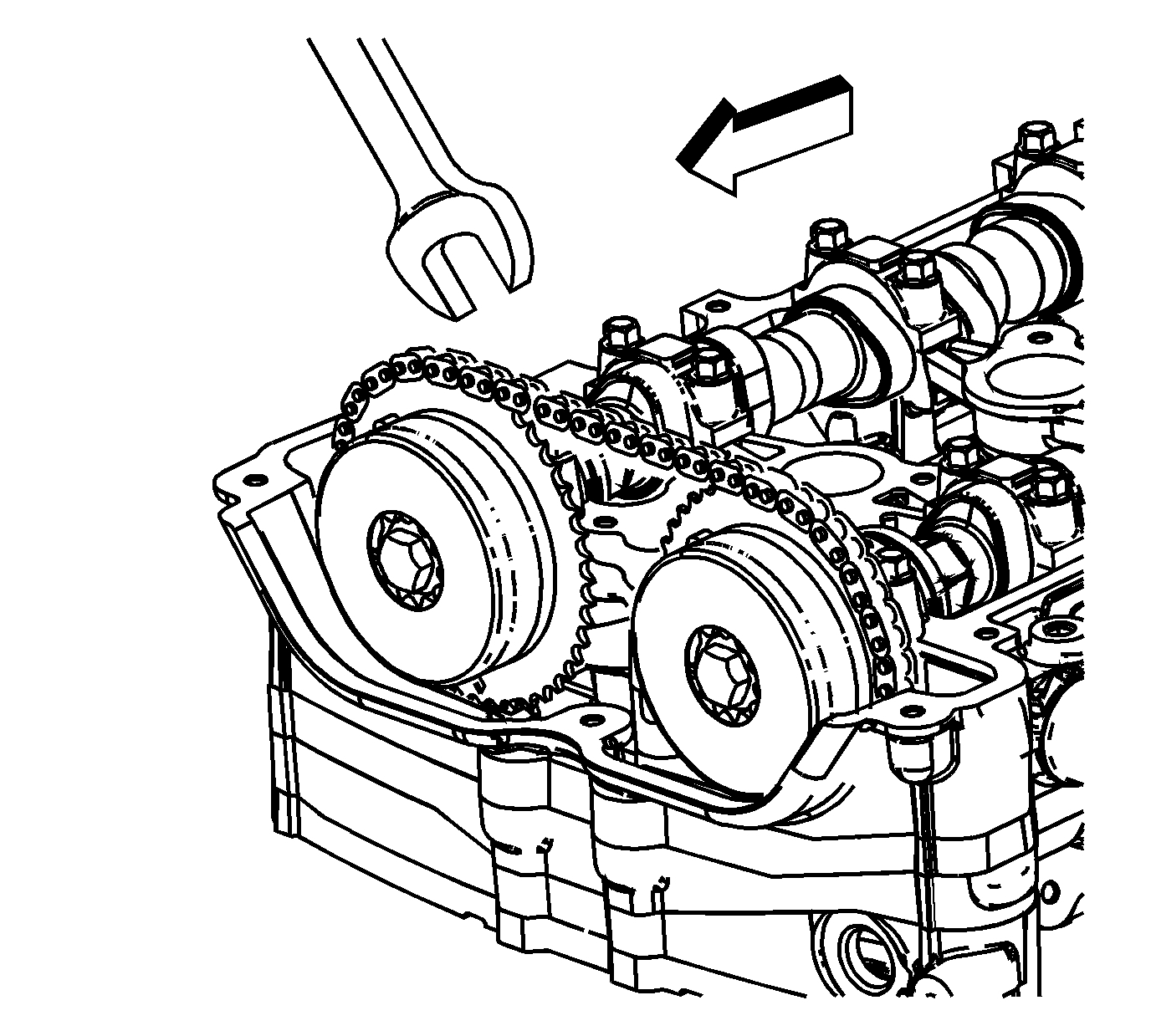
7. Install a 24 mm wrench on the hex on the exhaust camshaft in order to hold the camshaft.
8. Remove and discard the exhaust camshaft actuator bolt (2).
9. Remove the exhaust camshaft actuator (1, 3) from the camshaft and timing chain.
pic 9
10. Remove the timing chain tensioner guide bolt and guide.
pic 10
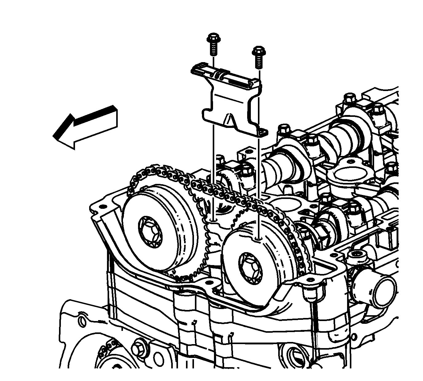
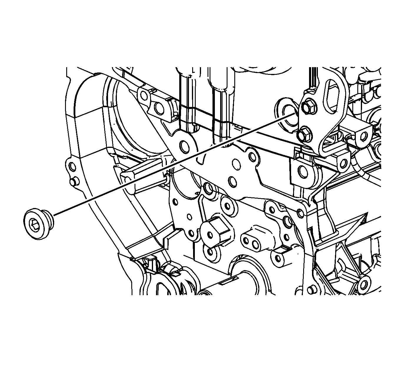
11. Remove the fixed timing chain guide access plug.
pic 11
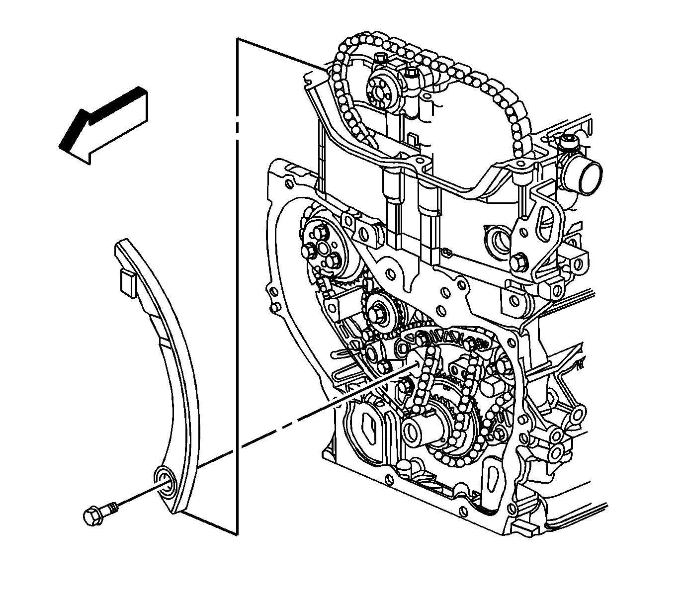
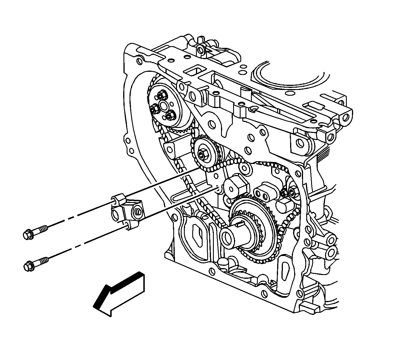
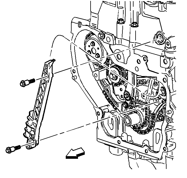
12. Remove the fixed timing chain guide bolts and guide.
pic 12
13. Install a 24 mm wrench on the hex on the intake camshaft in order to hold the camshaft.
14. Remove and discard the intake camshaft actuator bolt (2).
15. Remove the intake camshaft actuator (3), and the timing chain through the top of the cylinder head.
pic 13
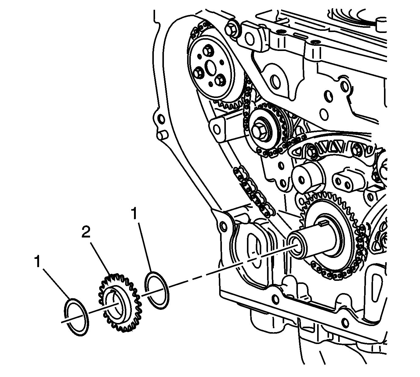
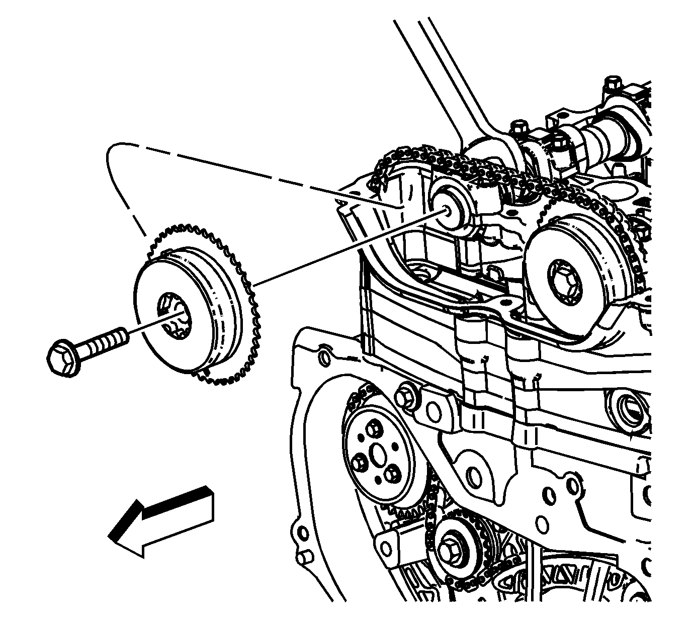
16. Remove the crankshaft sprocket (2) and friction washers (1), if equipped.
pic 14
17. If replacing the balance shaft timing chain and sprocket, perform the following steps, if not proceed to step 10 in the installation procedure.
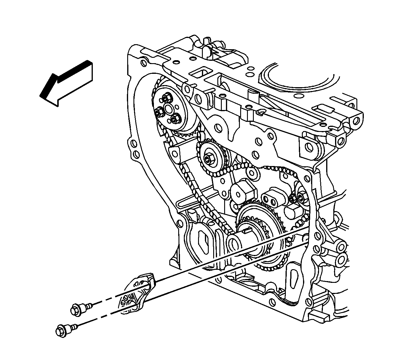
18. Remove the balance shaft drive chain tensioner bolts and tensioner.
pic 15
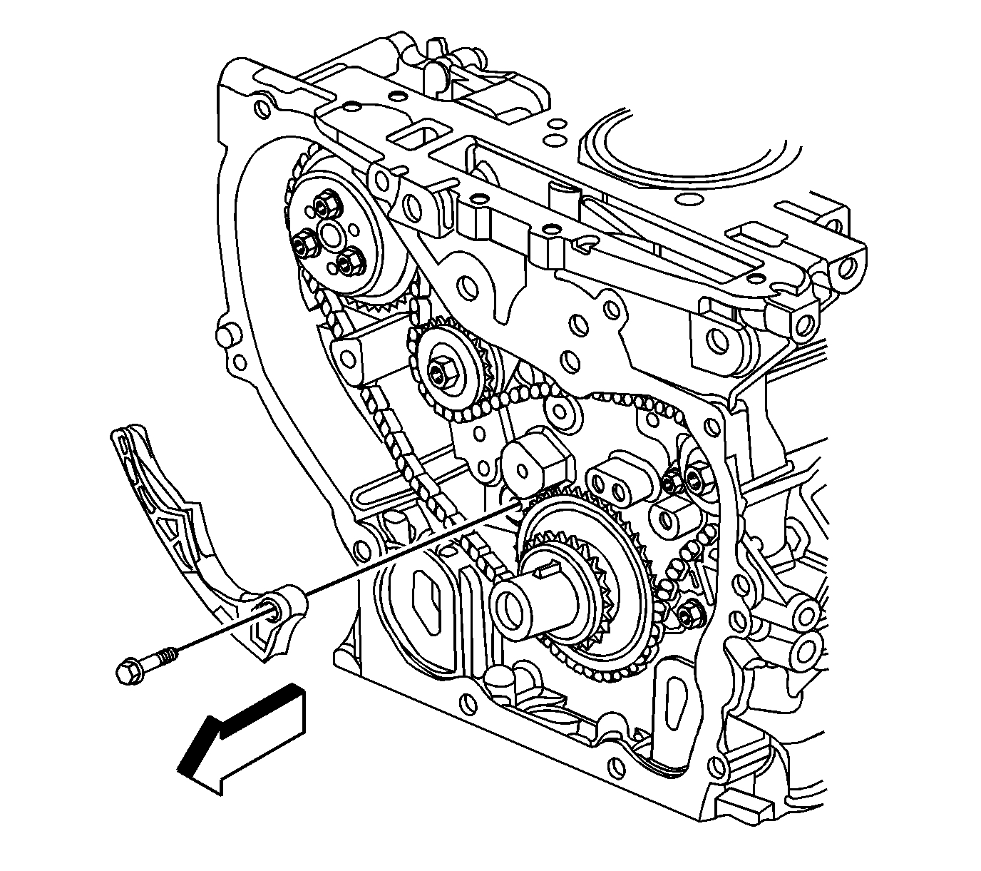
19. Remove the adjustable balance shaft chain guide bolt and guide.
pic 16
20. Remove the small balance shaft drive chain guide bolts and guide.
pic 17
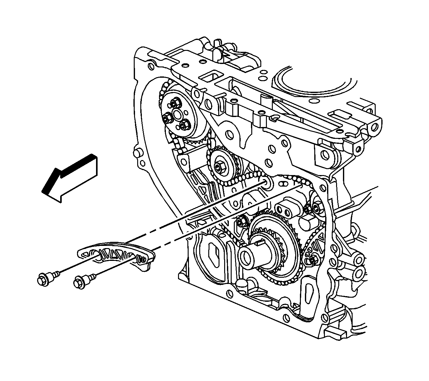
21. Remove the upper balance shaft drive chain guide bolts and guide.
pic 18
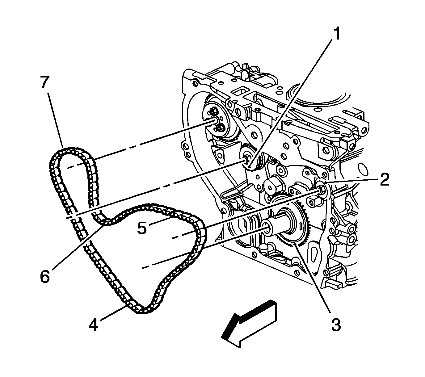
Note: It may ease removal of the balance shaft drive chain to get all the slack in the chain between the crankshaft and water pump sprockets.
22. Remove the balance shaft drive chain (7).
23. Remove the balance shaft drive sprocket.
Installation Procedure
pic 19
1. If replacing the balance shaft timing chain, perform the following steps, if not proceed to step 10.
2. Install the balance shaft drive sprocket.
Note: If the balance shafts are not properly timed to the engine, the engine may vibrate or make noise.
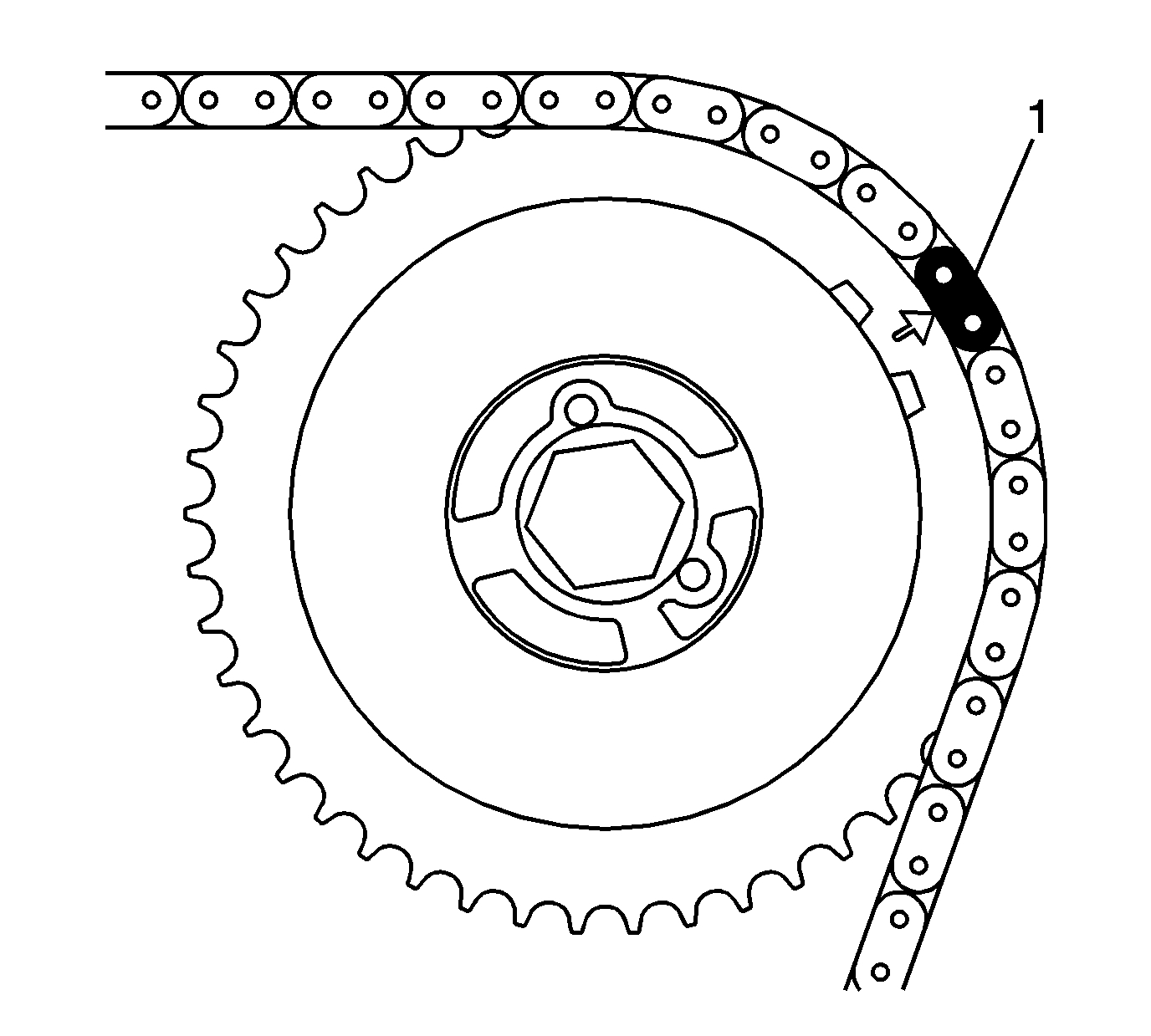
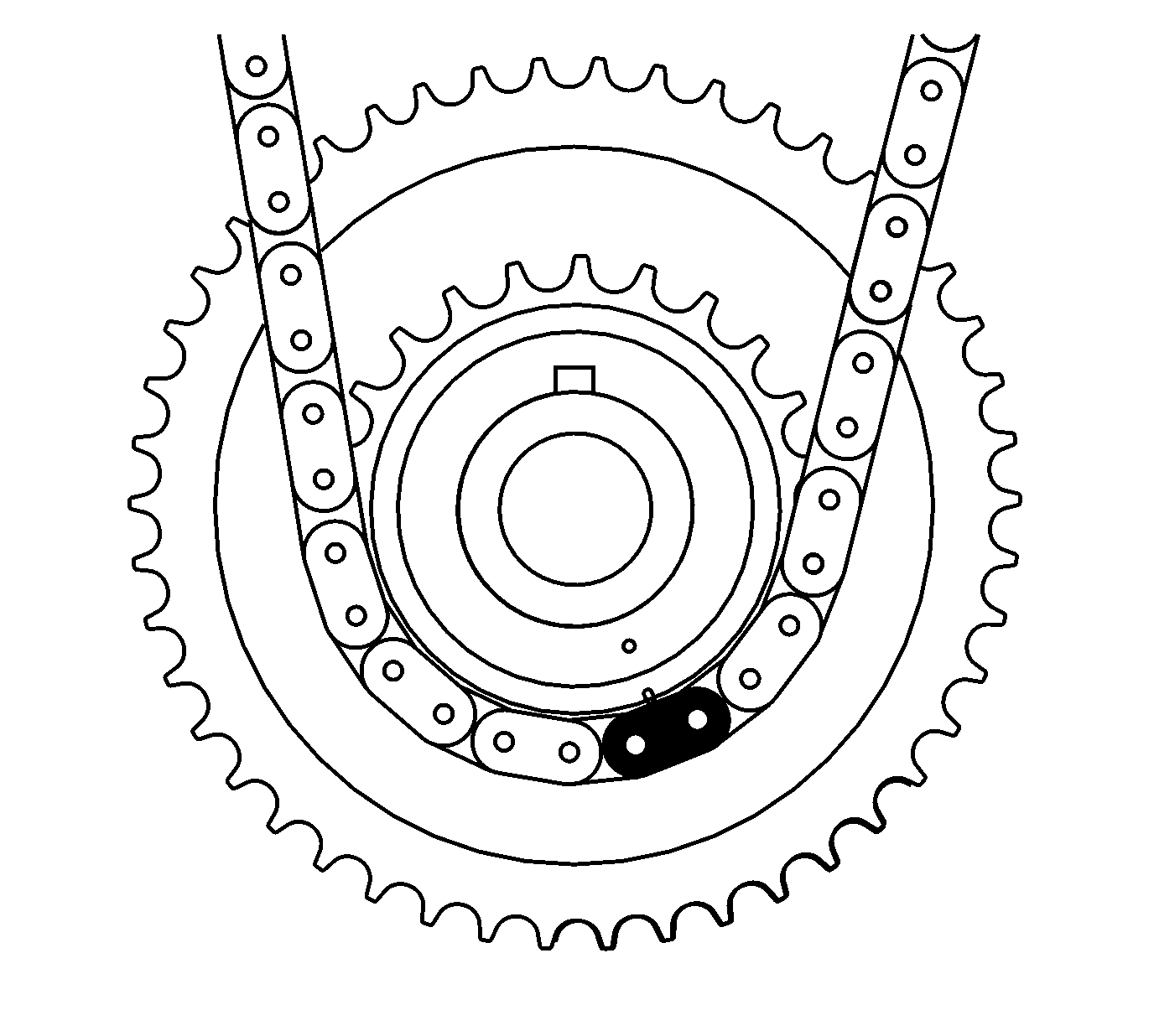
3. Install the balance shaft drive chain (7) with the colored link lined up with the marks on the balance shaft sprockets and the balance shaft drive sprocket. There are 3 colored links on the chain. Two are chrome and one is copper. Use the following steps in order to line up the links with the sprockets.
1. Place the copper link (5) so that it lines up with the timing mark (2) on the intake side balance shaft sprocket.
2. Working clockwise around the chain, place the chrome link (4) in line with the timing mark (3) on the balance shaft drive sprocket (approximately 6 o'clock position on the sprocket).
3. Place the chain (7) on the water pump drive sprocket. The alignment is not critical.
4. Align the last chrome link (6) with the timing mark (1) on the exhaust side balance shaft drive sprocket.
pic 20
Caution: Refer to Fastener Caution (See: Vehicle > Vehicle Damage Warnings > Fastener Caution).
4. Install the upper balance shaft drive chain guide and bolts and tighten to 15 Nm (11 lb ft).
pic 21
5. Install the small balance shaft drive chain guide and bolts and tighten to 15 Nm (11 lb ft).
pic 22
6. Install the adjustable balance shaft chain guide and bolt and tighten to 10 Nm (89 lb in).
pic 23
7. Reset the timing chain tensioner by performing the following steps:
1. Rotate the tensioner plunger 90 degrees in its bore and compress the plunger.
2. Rotate the tensioner back to the original 12 o'clock position and insert a paper clip through the hole in the plunger body and into the hose in the tensioner plunger.
8. Install the balance shaft drive chain tensioner and bolts and tighten to 10 Nm (89 lb in).
9. Remove the paper clip from the balance shaft drive chain tensioner.
pic 24
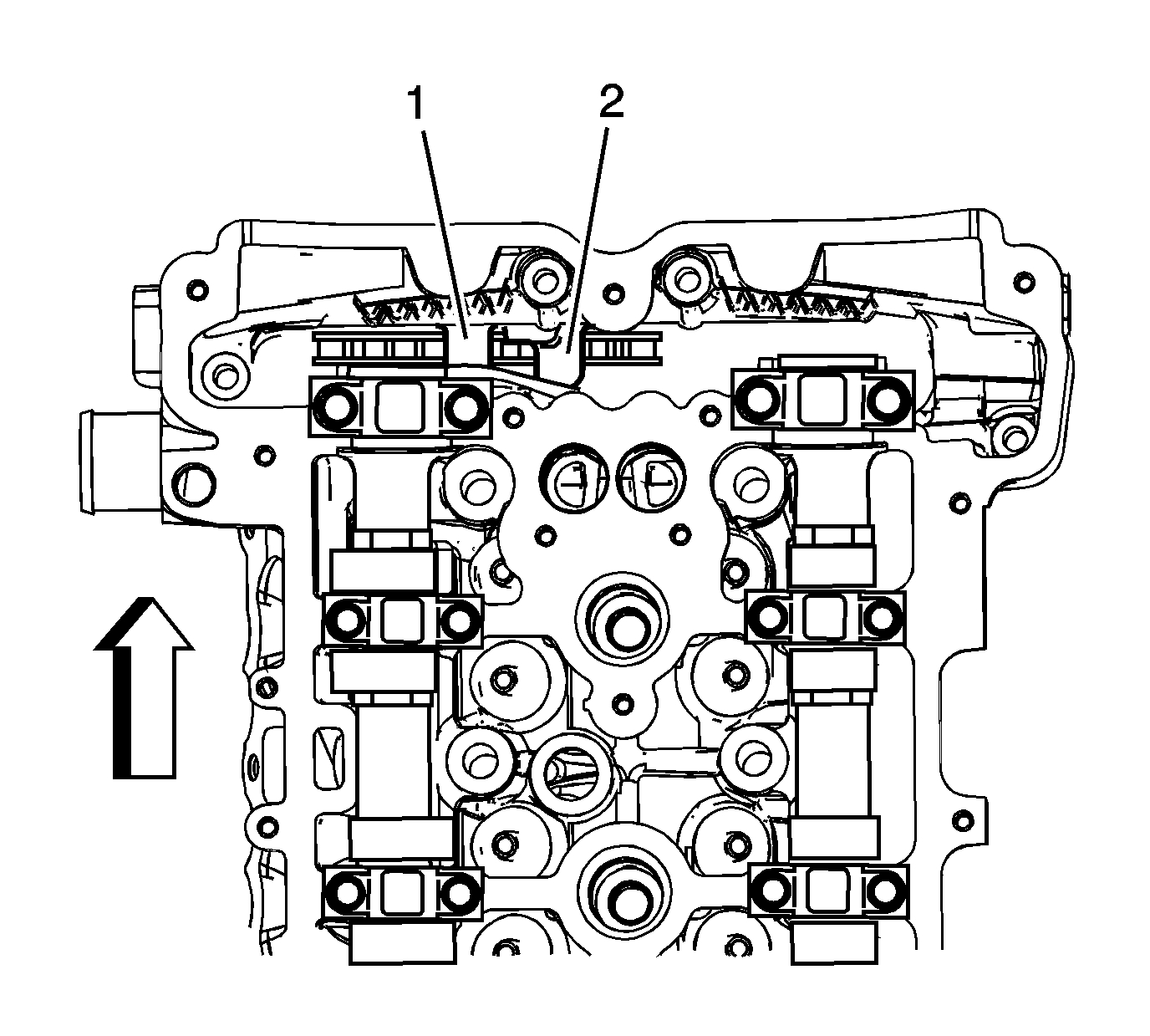
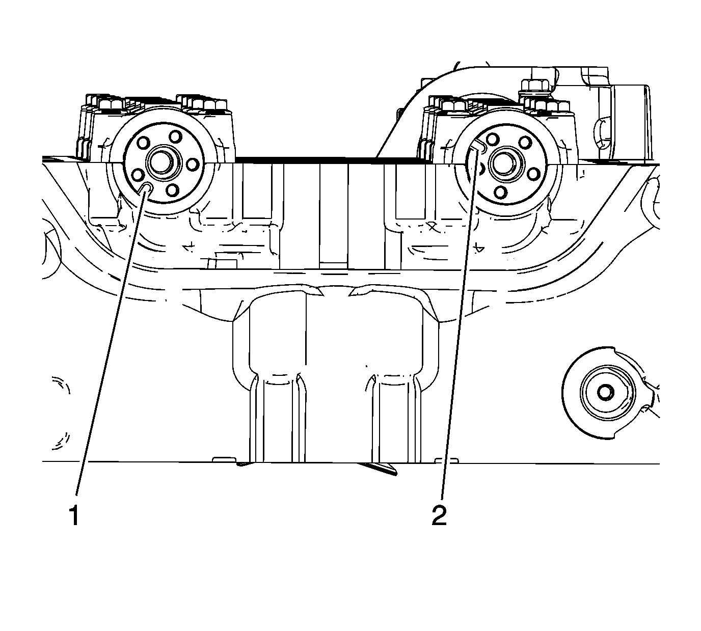
10. On 2.2L engines, ensure the intake camshaft notch is in the 10 o'clock position (2) and the exhaust camshaft notch is in the 7 o'clock position (1). The number 1 piston should be at TDC, crankshaft key at 12 o'clock.
pic 25
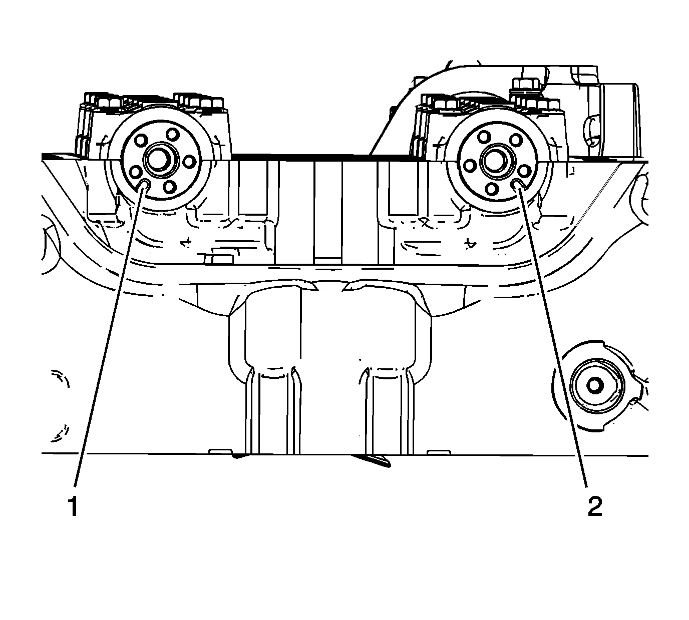
11. On 2.4L engines, ensure the intake camshaft notch is in the 5 o'clock position (2) and the exhaust camshaft notch is in the 7 o'clock position (1). The number 1 piston should be at TDC, crankshaft key at 12 o'clock.
pic 26
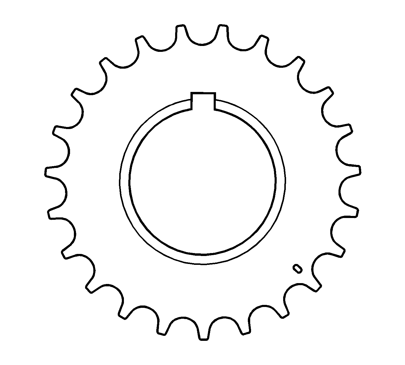
12. Install the friction washer, if applicable.
13. Install the timing chain drive sprocket to the crankshaft with the timing mark in the 5 o'clock position and the front of the sprocket facing.
pic 27
Note:
* There are 3 colored links on the timing chain. Two links are of matching color, and 1 link is of a unique color. Use the following procedure to line up the links with the actuators. Orient the chain so that the colored links are visible.
* Always use new actuator bolts.
14. Assemble the intake camshaft actuator into the timing chain with the timing mark lined up with the uniquely colored link (1).
pic 28
15. Lower the timing chain through the opening in the cylinder head. Use care to ensure that the chain goes around both sides of the cylinder block bosses (1, 2).
16. Install the intake camshaft actuator onto the intake camshaft while aligning the dowel pin into the camshaft slot.
17. Hand tighten the new intake camshaft actuator bolt.
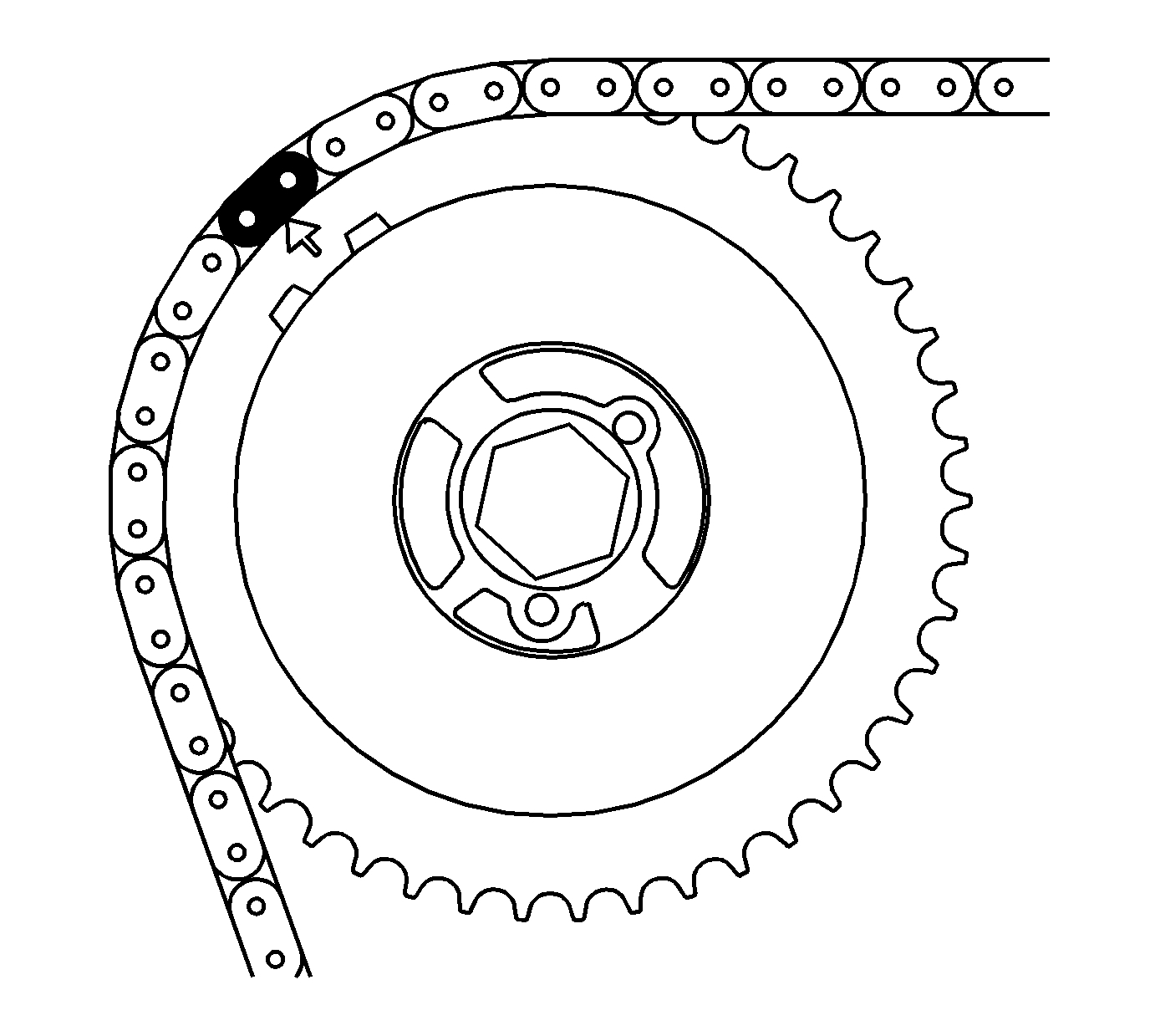
pic 29
18. Route the timing chain around the crankshaft sprocket and line up the first matching colored link with the timing mark on the crankshaft sprocket, in approximately the 5 o'clock position.
19. Install the friction washer, if applicable.
pic 30
20. Rotate the crankshaft clockwise to remove all chain slack. Do not rotate the intake camshaft.
21. Install the adjustable timing chain guide down through the opening in the cylinder head and install the adjustable timing chain bolt. Tighten the adjustable timing chain guide bolt to 10 Nm (89 lb in).
pic 31
Note: Always install NEW actuator bolts.
22. Install the exhaust camshaft actuator into the timing chain with the timing mark lined up with the second matching colored link.
pic 32
23. Install the exhaust camshaft actuator onto the exhaust camshaft, aligning the dowel pin into the camshaft slot.
24. Use 24 mm open ended wrench, rotate the exhaust camshaft approximately 45 degrees until the dowel pin in the camshaft actuator goes into the camshaft slot.
pic 33
25. When the actuator seats on the cam, tighten the new exhaust camshaft actuator bolt hand tight.
pic 34
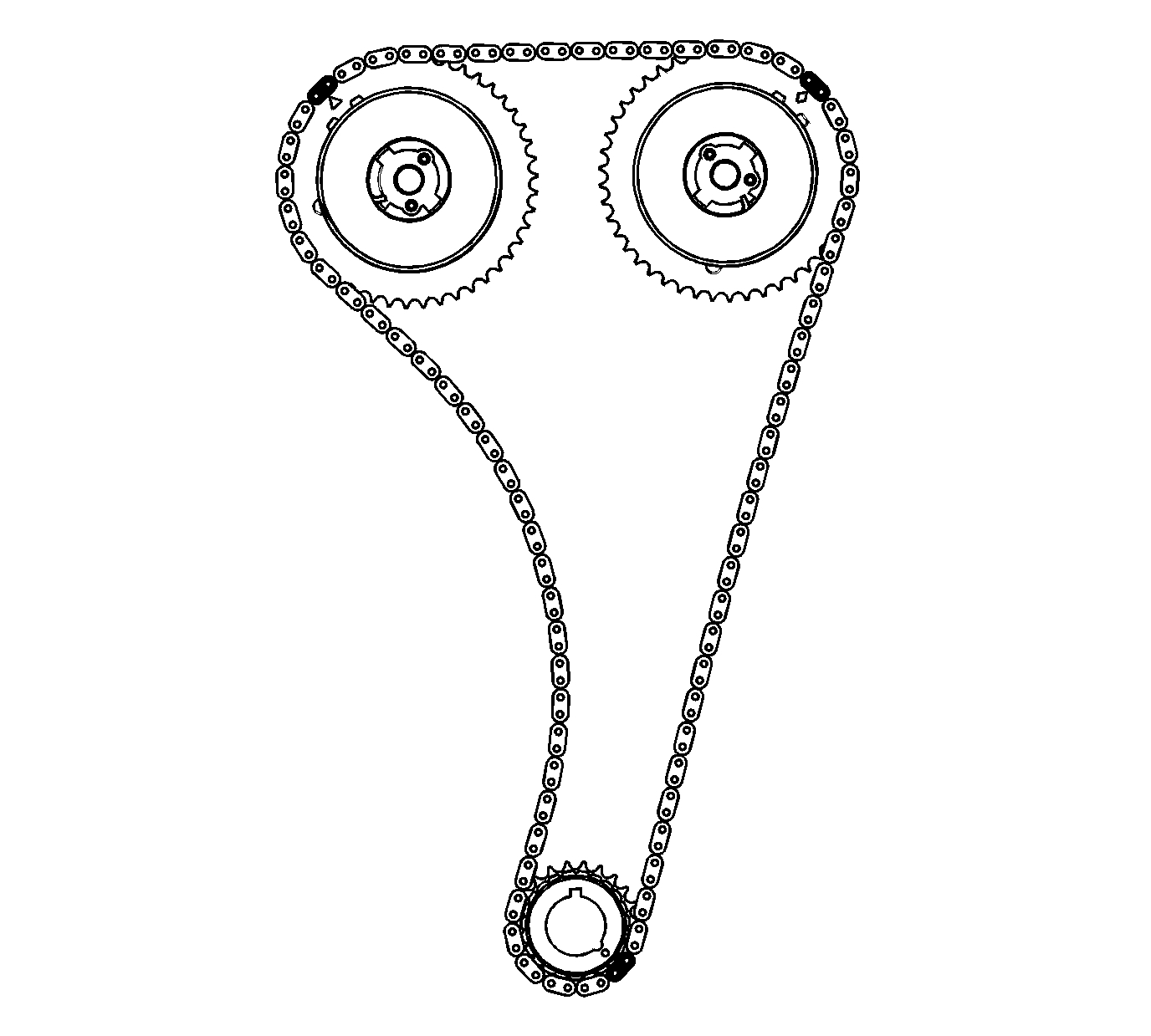
26. Verify that all of the colored links and the appropriate timing marks are still aligned. If they are not aligned, repeat the portion of the procedure necessary to align the timing marks.
pic 35
27. Install the fixed timing chain guide and bolts. Tighten the fixed timing chain guide bolts to 12 Nm (106 lb in).
pic 36
28. Install the upper timing chain guide and bolts. Tighten the upper timing chain guide bolts to 10 Nm (89 lb in).
pic 37
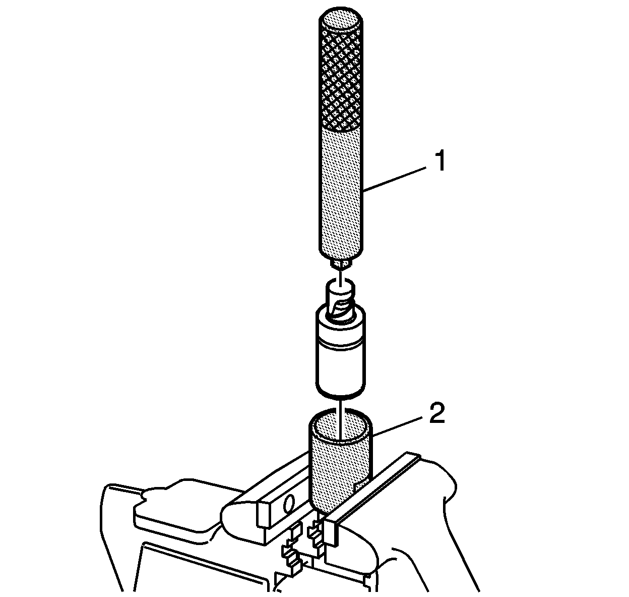
29. Reset the timing chain tensioner by performing the following steps:
1. Remove the snap ring.
2. Remove the piston assembly from the body of the timing chain tensioner.
3. Install the EN-45027-2 - tool (2) into a vise.
4. Install the notch end of the piston assembly into the EN-45027-2 - tool (2).
5. Using the EN-45027-1 - tool (1), turn the ratchet cylinder into the piston.
6. Reinstall the piston assembly into the body of the tensioner.
7. Install the snap ring.
pic 38
30. Inspect the timing chain tensioner seal for damage. If damaged, replace the seal.
31. Inspect to ensure all dirt and debris is removed from the timing chain tensioner threaded hole in the cylinder head.
Note: Ensure the timing chain tensioner seal is centered throughout the torque procedure to eliminate the possibility of an oil leak.
32. Install the timing chain tensioner assembly. Tighten the timing chain tensioner to 75 Nm (55 lb ft).
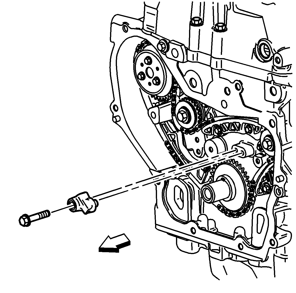
33. The timing chain tensioner is released by compressing it 2 mm (0.079 in), which will release the locking mechanism in the ratchet. To release the timing chain tensioner, use a suitable tool with a rubber tip on the end. Feed the tool down through the cam drive chest to rest on the cam chain. Then give a sharp jolt diagonally downwards to release the tensioner.
pic 39
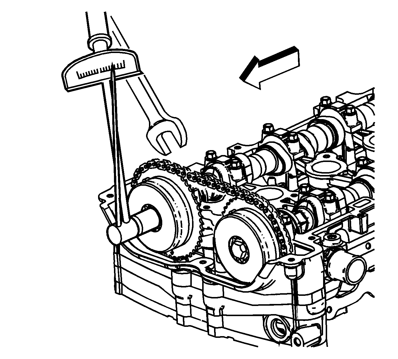
34. Using a 24 mm wrench, engage the hex on the intake camshaft, and using a torque wrench, tighten the camshaft actuator bolt. Tighten the intake camshaft position actuator bolt to 30 Nm (22 lb ft) plus 100 degrees using the EN-45059 - meter.
35. Using a 24 mm wrench, engage the hex on the exhaust camshaft, and using a torque wrench, tighten the camshaft actuator bolt. Tighten the exhaust camshaft position actuator bolt to 30 Nm (22 lb ft) plus 100 degrees using the EN-45059 - meter.
pic 40
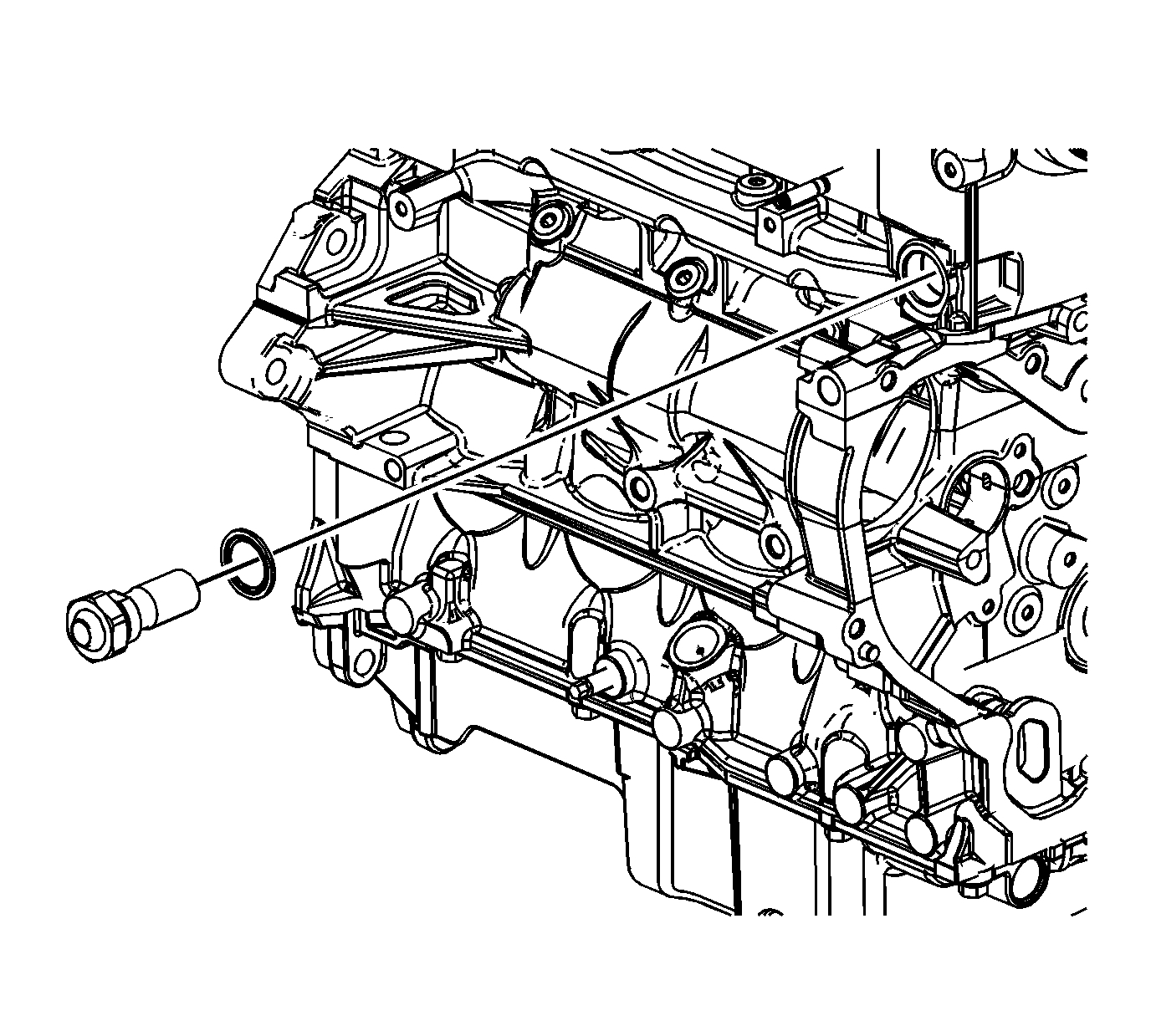
36. Install the timing chain oiling nozzle. Tighten the timing chain oiling nozzle bolt to 10 Nm (89 lb in).
pic 41
37. Apply sealant compound to the thread of the timing chain guide bolt access hole plug. Refer to Adhesives, Fluids, Lubricants, and Sealers (See: Engine > Mechanical > Adhesives, Fluids, Lubricants, and Sealers) for the recommended sealant.
38. Install the timing chain guide bolt access hole plug. Tighten the access hole plug to 90 Nm (66 lb ft).
39. Install the engine front cover. Refer to Engine Front Cover Replacement (See: Timing Cover > Removal and Replacement).
40. Install the camshaft cover. Refer to Camshaft Cover Replacement (See: Valve Cover > Removal and Replacement > Camshaft Cover Replacement).
41. Install the number 1 cylinder spark plug. Refer to Spark Plug Replacement (See: Spark Plug > Removal and Replacement).
_________________________
I know that is a lot of work, but figured I would add it in case you wanted to do it yourself.
Let me know if you have questions and how things turn out.
Take care,
Joe
Images (Click to enlarge)
Aug 19, 2019 at 8:02 PM