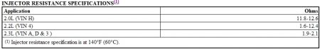
Canister Purge Solenoid (Normally Closed) 1. Disconnect canister purge solenoid harness connector and vacuum hose. Apply 10 in. Hg to ported intake manifold vacuum side of solenoid valve. If vacuum holds, go to next step. If vacuum does not hold, replace canister purge solenoid. 2. Using a 12-volt power source, energize canister purge solenoid. Vacuum should release. If vacuum does not release, replace canister purge solenoid. Solenoid resistance should be at least 20 ohms. Fuel Tank Pressure Control Valve Apply approximately 15 in. Hg to fuel tank pressure control valve. The diaphragm should hold vacuum for at least 20 seconds. If fuel tank pressure control valve does not hold vacuum, replace tank pressure control valve. POSITIVE CRANKCASE VENTILATION (PCV) Required Service The PCV system may require service for obstructions if any of the following conditions exist: ï¬ Rough idle. ï¬ Stalling or slow idle speed. ï¬ Oil leaks. ï¬ Oil in air cleaner. ï¬ Sludge in engine. A leaking PCV valve or hose could cause: ï¬ Rough idle. ï¬ Stalling. ï¬ High idle speed. If engine idles roughly, check for clogged PCV valve or plugged or broken hoses BEFORE adjusting idle. Check PCV valve application to ensure the correct valve is fitted. Replace PCV valve if required. Checking PCV Valve Function 1. Remove PCV valve from rocker cover. Run engine at idle. Place thumb over open end of valve to check for vacuum. If there is no vacuum at valve, check for obstruction in manifold port, hoses or PCV valve. Repair or replace as necessary. 2. Turn engine off. Remove PCV valve. Shake valve and listen for rattle of check valve inside. If a clear rattle is not heard, replace PCV valve. 3. Visually inspect valve for varnish or deposits which may make PCV valve operation sticky or restricted, or cause incomplete seating of valve. Replace if necessary. 4. An engine must be sealed for the PCV system to function as designed. If leakage, sludging or dilution of oil is noted and the PCV system is functioning properly, check engine for cause and repair as required to ensure PCV system will continue to function properly. 5. An engine operating without any crankcase ventilation can be damaged, so it is important to replace PCV valve and air cleaner breather (if equipped) at regular intervals (at least every 30,000 miles). Check all hoses and clamps for failure or deterioration. Crankcase Ventilation Heater (2.3L) 1. Turn ignition on. Connect test light between crankcase ventilation heater assembly connector. See Fig. 6 . Test light should illuminate. If test light did not illuminate, check 25-amp A/C- heater fuse or for an open in circuit. If test light illuminated, go to next step. 2. Turn ignition off. Disconnect harness connector from crankcase ventilation heater assembly. Using an ohmmeter, measure crankcase ventilation heater resistance at room temperature. Resistance should be 2-6 ohms. If resistance is as specified, go to next step. If resistance is not as specified, replace crankcase ventilation heater assembly. 3. Reconnect crankcase ventilation heater assembly harness connector, but DO NOT install assembly on engine. Turn ignition on for one minute. Heating element should be warm to the touch. If heating element does not warm up, inspect wiring harness and harness connector for proper connection or replace defective crankcase ventilation heater assembly. Fuel Pressure Regulator (PFI) 1. Install fuel pressure gauge to fuel rail fuel pressure test fitting. Remove vacuum hose from fuel pressure regulator. Turn ignition on and note fuel pressure on gauge. 2. Start engine. Check for manifold vacuum at pressure regulator vacuum hose. If vacuum is not present, repair as necessary. Reconnect vacuum hose to pressure regulator and note fuel pressure on gauge. Compare first and second reading. 3. Fuel pressure reading should be 4-7 psi (.28-.49 kg/cm 2 ) less with vacuum hose installed. Fuel pressure should decrease as vacuum increases. If results are not as specified, replace fuel pressure regulator. Fuel Pressure Regulator (TBI) Fuel pressure regulator is mechanically controlled by internal spring pressure. Regulator is adjusted at factory and is not serviceable. If fuel pressure is too low, check fuel filter, fuel pump pressure and volume. If fuel pressure is too high, check for restricted fuel tank return line. If no faults are found and pressure is too high or too low, replace fuel pressure regulator. Fuel Pump Relay (A-5) 1. Disconnect fuel pump relay connector. See COMPONENT LOCATIONS at the end of this article to locate fuel pump relay. Apply battery voltage and ground to fuel pump relay winding terminals. To identify fuel pump relay terminals, see appropriate wiring diagram in the WIRING DIAGRAMS article in this section. 2. Using an ohmmeter, check for continuity between fuel pump relay power supply terminal and fuel pump drive terminal. Continuity should exist ONLY with relay energized. If relay does not test as indicated, replace relay. 3. To by-pass fuel pump relay (to test fuel pump and wiring when fuel pump is not energizing), see FUEL PUMP RELAY BY-PASS PROCEDURE below. Fuel Pump Relay By-Pass Procedure 1. If fuel pump will not energize, relay may be by-passed to test fuel pump and related wiring. See Fig. 4 . Turn ignition off. Disconnect fuel pump relay connector. Using a fused jumper wire, apply battery voltage to fuel pump test connector (located in engine compartment). For fuel pump test connector location, see COMPONENT LOCATIONS at end of this article. See Fig. 37 - Fig. 43 . 2. If fuel pump runs and relay tests okay, check for faulty connections at relay. If fuel pump does not run, check for faulty wiring between relay and fuel pump or replace defective fuel pump. Fig. 4: Fuel Pump Relay Schematic (Typical) Courtesy of GENERAL MOTORS CORP. Oil Pressure Switch Fuel Pump Back-Up With engine idling, disconnect fuel pump relay. Engine should continue to run through oil pressure switch back-up circuit. If engine stalls, check oil pressure switch and related wiring. FUEL CONTROL Fuel Injector(s) Disconnect fuel injector harness connector. Measure resistance across injector terminals at each injector. Resistance should be as specified.
Aug 20, 2010 at 10:27 AM