Code 0037DE, Crankcase Ventilation Heating Open Circuit?

2013 MINI COUNTRYMAN
98,000 MILES • 1.6L • 4 CYL • 2WD • AUTOMATIC
Avatar
  • MEMBER
  • 7 POSTS
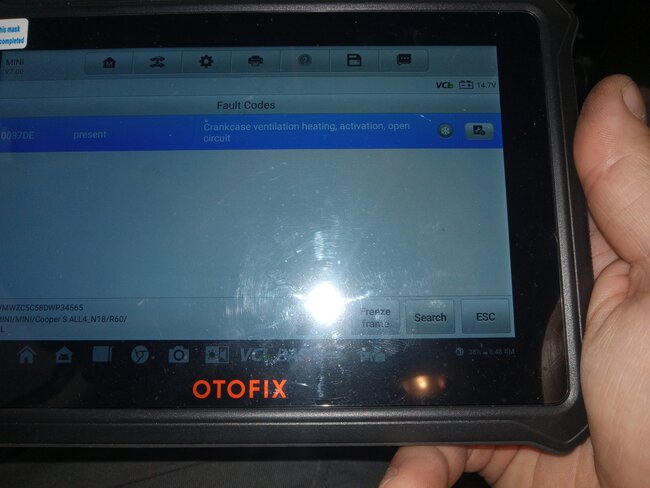
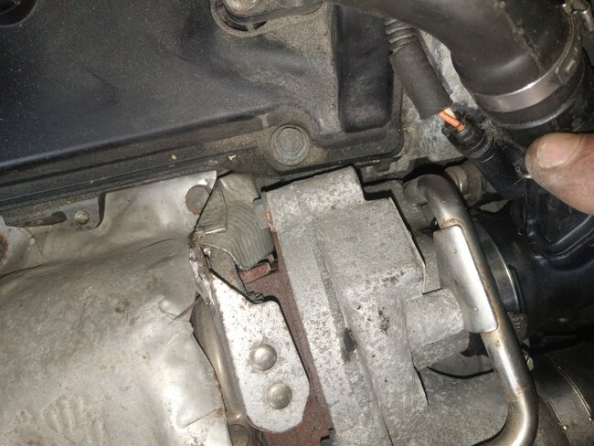
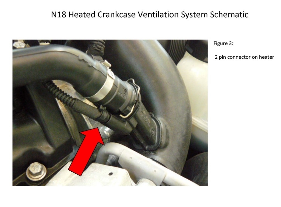
Hello. I replaced the Crankcase Heater -Comes Complete in a Hose Assembly.
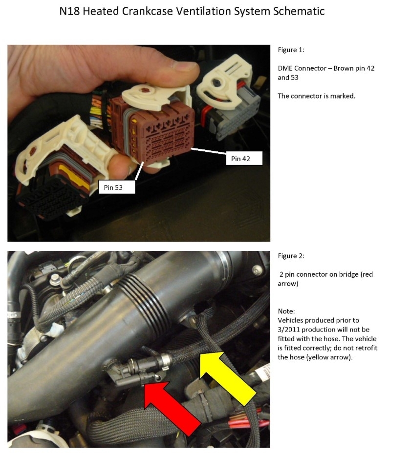
When i measured Voltage across the 2 pin plug there was .30V present.
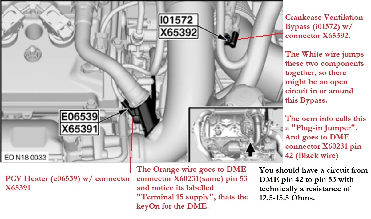
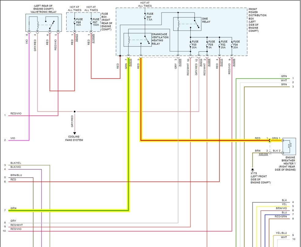
When measuring ground on engine and power on the red wore of the Crankcase Heater plug, 12 volts is present. So, i figured to replace the Crankcase Heater. Still has the same issue and code won't clear. The power side is good.
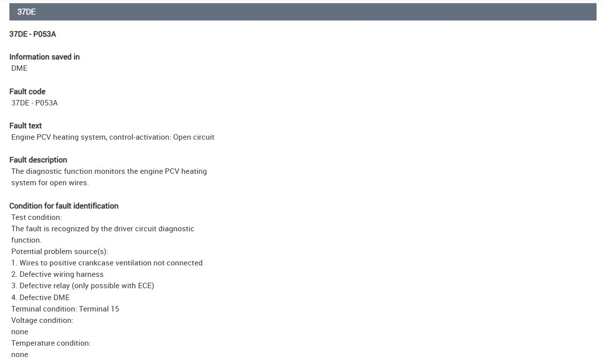
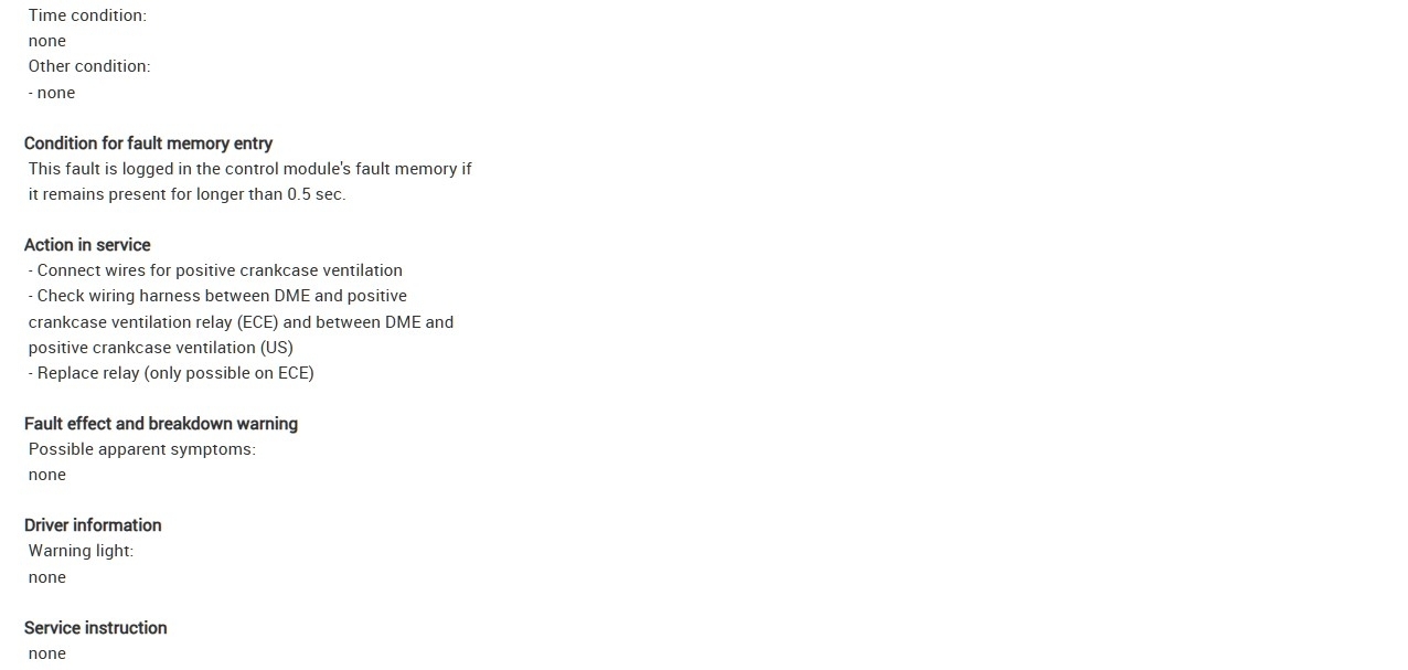
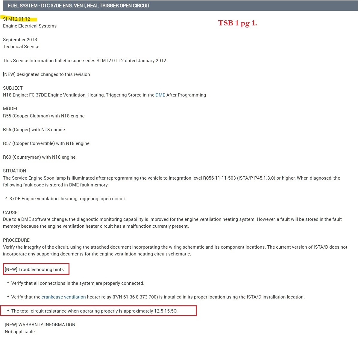
There is a NTSB Emissions Bulletin that says there is a Calibration issue inside the DME that may require a calibration upgrade(reflash). It also states to verify the integrity of the circuit from the Crank Case Heater and DME.

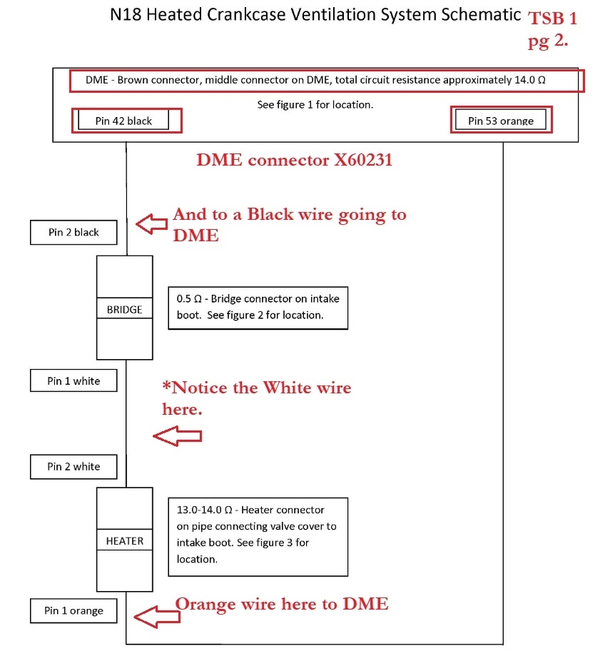
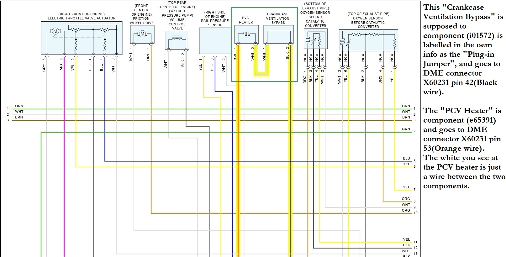
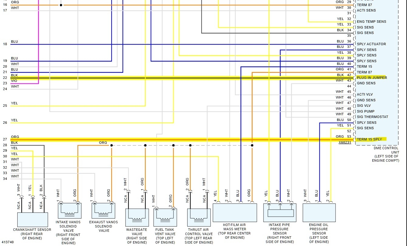
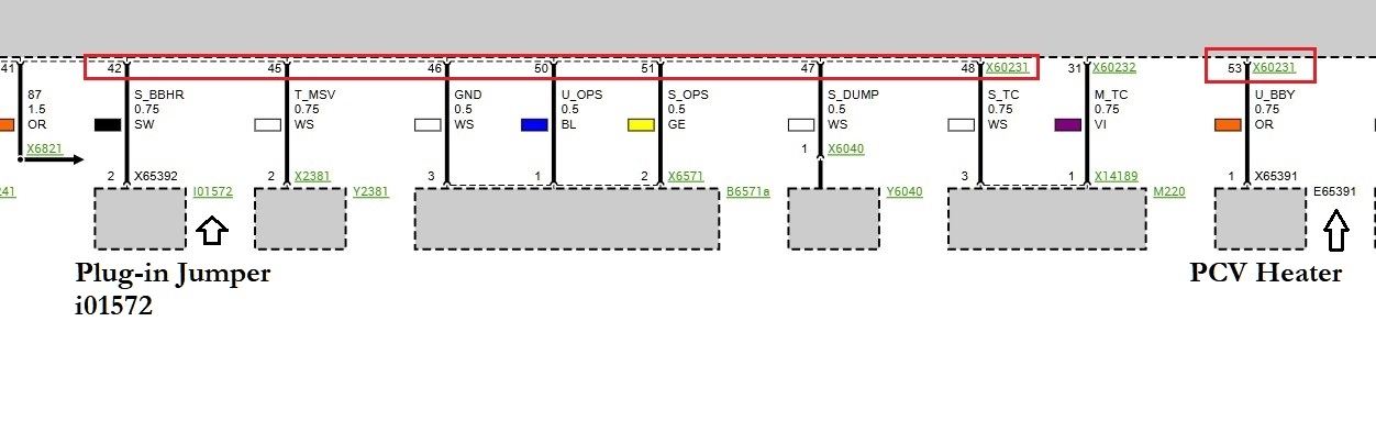
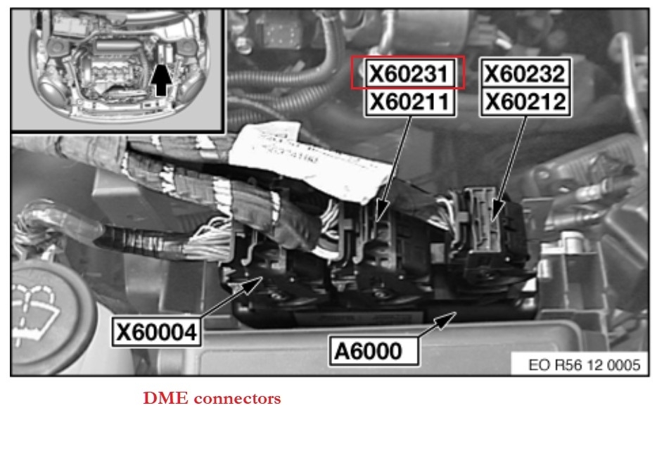
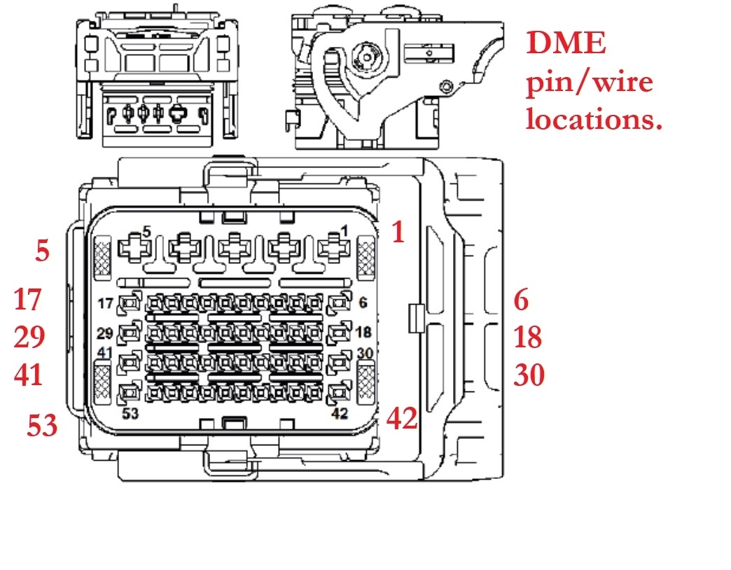
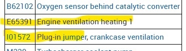
My Question to you guys' is could you provide me with a Circuit Schematic for the Crankcase Heater-White Wire to DME is what i need to trace. I'm helping out a coworker.
Any help is much appreciated.
Jun 2, 2025 at 12:05 PM
Advertisement
Avatar
  • MEMBER
  • 7 POSTS
Also, just to mention. The Plug for the CC Heater is all the way in and in the proper position. I double and triple checked. I know that's a common error on this vehicle.
Jun 2, 2025 at 12:11 PM
Avatar
AL514
  • CERTIFIED EXPERT
  • 5,462 POSTS
Hello, from a quick look at the wiring diagrams, and these were the aftermarket ones which Ill post both the OEM and these ones, it looks like the Engine Breather Heater has a red wire that comes directly from the Crankcase Ventilation Heating Relay. And the other wire which looks to be brown, you can verify that for me, is supposed to be just a Ground wire, so you may just have a bad ground in this case, but I will pull up the proper diagrams and service info. Can you provide the vin#, there are of course, a few different Countrymen listed.
But check the Brown wire for a path to ground for now, just don't provide it a ground yet until I can find it in the OEM wiring, because service info is not allows correct on circuit design.,
Jun 3, 2025 at 10:13 AM
Advertisement
Avatar
AL514
  • CERTIFIED EXPERT
  • 5,462 POSTS
I see part of the code you are getting, (0037DE) can you post the rest if there is more? That way any TSBs or recalls relating to it should show up with the code. The wiring diagrams are a little different also, the OEM wiring shows (E65391-Engine ventilation heating 1) with an orange wire that looks to go to the DME at connector X60231, pin 53, and Ill post all this in a minute. I see you have two wires in your picture; there are some TSBs with a code "37DE Eng. Vent, Heat, Trigger Open Circuit". And there are a couple more as well, so I just need to know the correct vehicle, I know they all have pretty much the same engine except the non-turbo, so I just want to be sure I'm giving you the correct service information.
Also did this vehicle just have a new DME programmed to it?
Jun 3, 2025 at 10:42 AM
Avatar
AL514
  • CERTIFIED EXPERT
  • 5,462 POSTS
Okay, there are two different heaters here, a PCV and Engine Breather Heater(which I assume is a heater possibly on the intake boot area to heat incoming air), the PCV heater does have the Orange and White wire going to it with a crankcase ventilation bypass, so I am just going to go by the code that's set (37DE) and take it from there. The PCV heater has the two wires and they both go to the DME.
Jun 3, 2025 at 11:02 AM
Avatar
  • MEMBER
  • 7 POSTS
Yes. Would you have access to the Wiring Schematic?
Jun 3, 2025 at 11:49 AM
Avatar
AL514
  • CERTIFIED EXPERT
  • 5,462 POSTS
Yup I'm getting the info together for you right now, the service information on these vehicles can be tricky to understand, so it's a little slow at the beginning. But I think I have it sorted out. It will be testing from the DME connector on two different pins to see if the circuit is open anywhere, the white wire on the (orange and white wire connector) is just a jumper between another component. You will see in the diagrams what I mean. But give me one more minute here and Ill post it all.
Jun 3, 2025 at 11:54 AM
Avatar
AL514
  • CERTIFIED EXPERT
  • 5,462 POSTS
okay, this should be all you need, I know its a lot of info, but I wanted to be sure we're looking at the correct components. If you follow the TSB (diagrams 3-6) it pretty much shows the circuit, connectors and where the wires change colors, I would check the White wire between the two components really quick from connector to connector and make sure it's not open or shorted to ground. Thats just a fast check to do. As for the rest I hope it's all correct, euro wiring doesn't always show the complete circuit, but the aftermarket diagram does (7-8). Along with the DME and its connector pinouts. Let me know what you find.
Jun 3, 2025 at 12:33 PM
Avatar
  • MEMBER
  • 7 POSTS
I just went.over all of the material and it's so helpful. Evidently the photo i sent you was the PCV Heater and CCHeater on the other side of the tube. But none-the-less it's the same white wire i been chasing and the info nails it.

I will try to get to him tommorow after work. To check the white wire component to component.
Jun 3, 2025 at 4:08 PM
Avatar
AL514
  • CERTIFIED EXPERT
  • 5,462 POSTS
Yeah it's a little confusing with the way they label things, In the components lists its different too calling it an Engine ventilation heating 1, this was the first component (diagram) I thought it might be, but then checking to code sent things in a different direction.
Engine Breather Heater 1 sounds like a PCV heater to me, but apparently its probably some intake air heater, idk, but at least the bulletin gives a clearer picture of the circuit we're dealing with. I can see how this can easily be an open on any of those 3 wires. But if you have 12volts on the orange wire while grounding from a different location, that wire should be fine. The Terminal 15 power on is the DME power on signal too if I remember correctly. I'm not sure how much current that heater pulls, and considering the power is coming from the DME, I wouldn't load test it to excessively, don't want to burn out anything internal on that. Let me know what you find.
Jun 3, 2025 at 4:32 PM
Avatar
  • MEMBER
  • 7 POSTS
Yes for sure.
Jun 3, 2025 at 4:34 PM
Avatar
AL514
  • CERTIFIED EXPERT
  • 5,462 POSTS
Did you send an additional message after "Yes for sure"? Just checking, I got a notification for a new message but can't seem to access it, unless it's a glitch.
Jun 3, 2025 at 6:46 PM
Avatar
  • MEMBER
  • 7 POSTS
No, sorry.
Jun 3, 2025 at 7:57 PM
Avatar
AL514
  • CERTIFIED EXPERT
  • 5,462 POSTS
No problem,, have a good night.
Jun 3, 2025 at 8:06 PM
Avatar
  • MEMBER
  • 7 POSTS
Hello, the concern is resolved. All of the circuit tests proved out.
It turns out that the connector was not in all of the way. Even though i checked it multiple times and it seemed like it was bottomed down. I did'nt want to damage the tiny connector or the CCH. So once the entire connector shell is passed that retaining clip and only the wires can be seen begind the retainer it makes contact. So the connector shell has to disapear behind the retainer.
I cleared the code and retested, all good. Retest again for 2 ignition cycles and good.
The more you know.
Lol
Could you send a link to your GoFundMe ?
Thanks.
Jun 4, 2025 at 2:15 PM
Avatar
AL514
  • CERTIFIED EXPERT
  • 5,462 POSTS
Thanks I appreciate it, I don't have a GoFundMe set up yet, I do have a PayPal account. I just very rarely get tips. I think only once before.
Jun 4, 2025 at 2:41 PM
Avatar
STRAILER
  • CERTIFIED EXPERT
  • 53,854 POSTS
AL514, do you have a link? please post it here.
Jun 23, 2025 at 6:01 PM
Avatar
AL514
  • CERTIFIED EXPERT
  • 5,462 POSTS
This is the link to my PayPal account I have:

https://www.paypal.com/paypalme/AlanWoro
Jun 23, 2025 at 7:30 PM