Alternator C1 connection wires?

2013 DODGE DURANGO
140,000 MILES • 5.7L • V8 • 2WD • AUTOMATIC
Avatar
KASEY BROCK
  • MEMBER
  • 1 POST
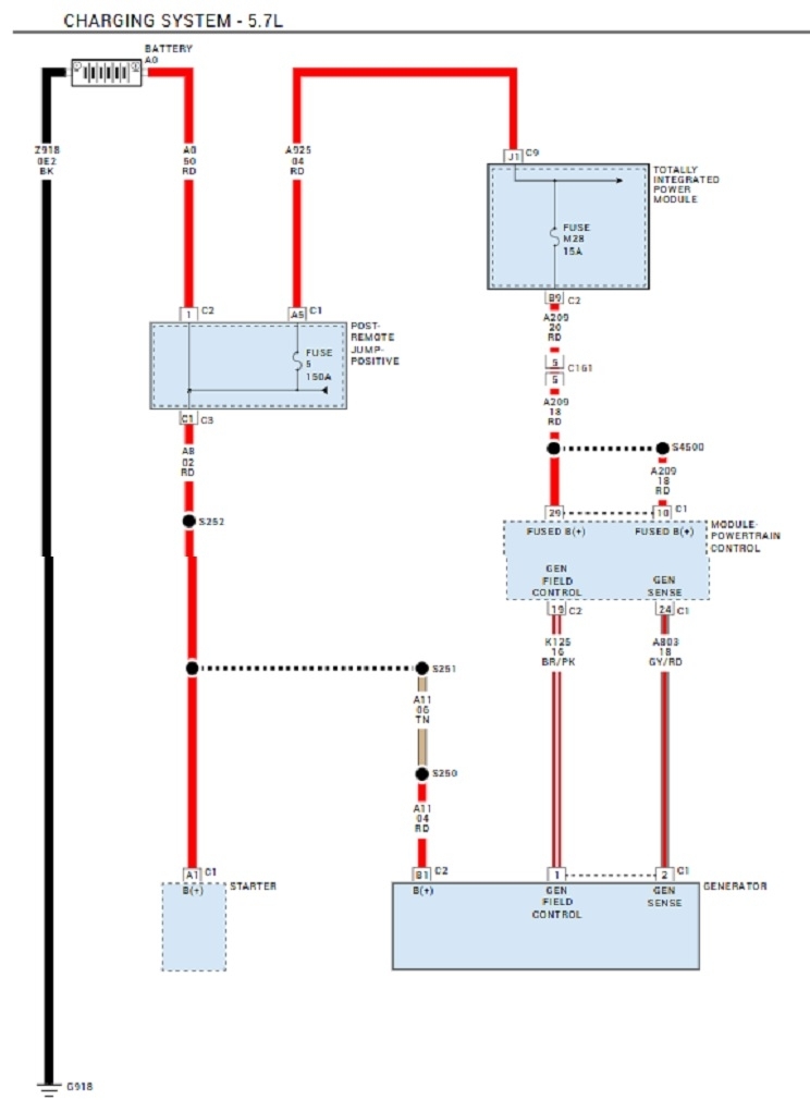
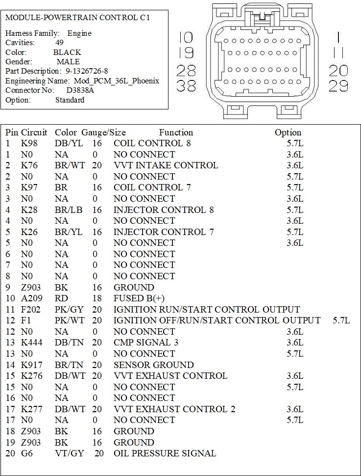
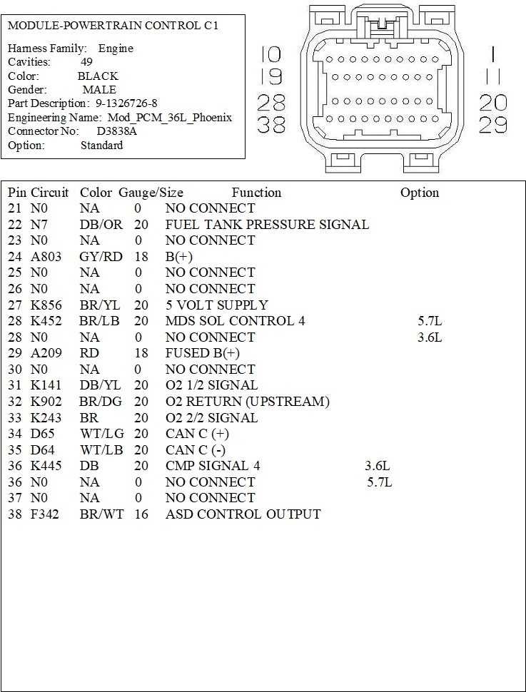
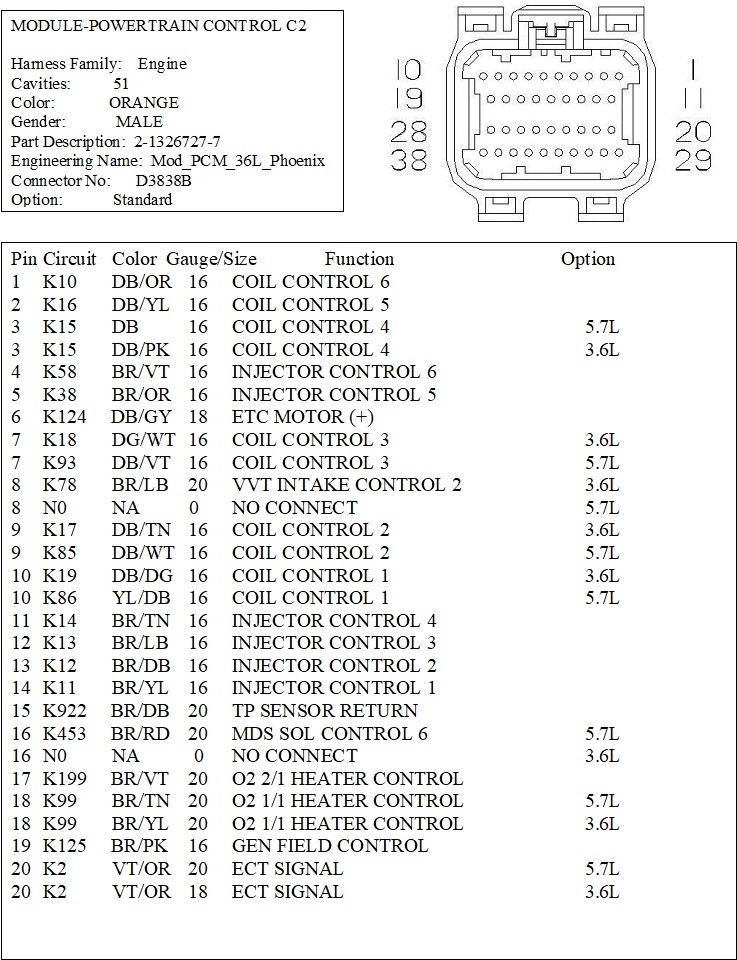
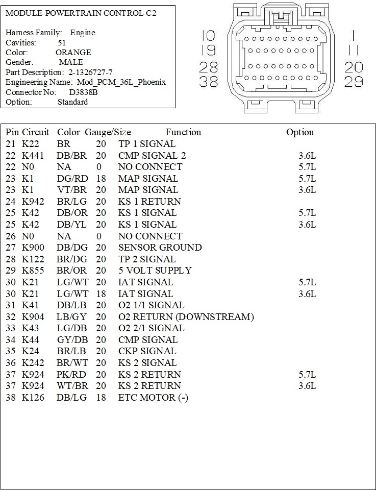
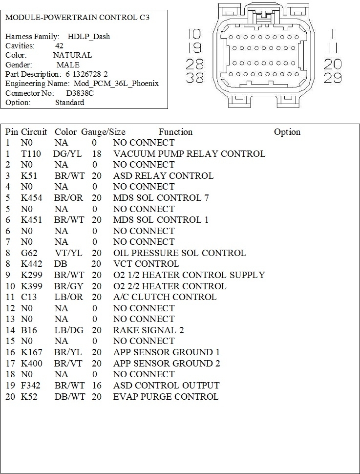
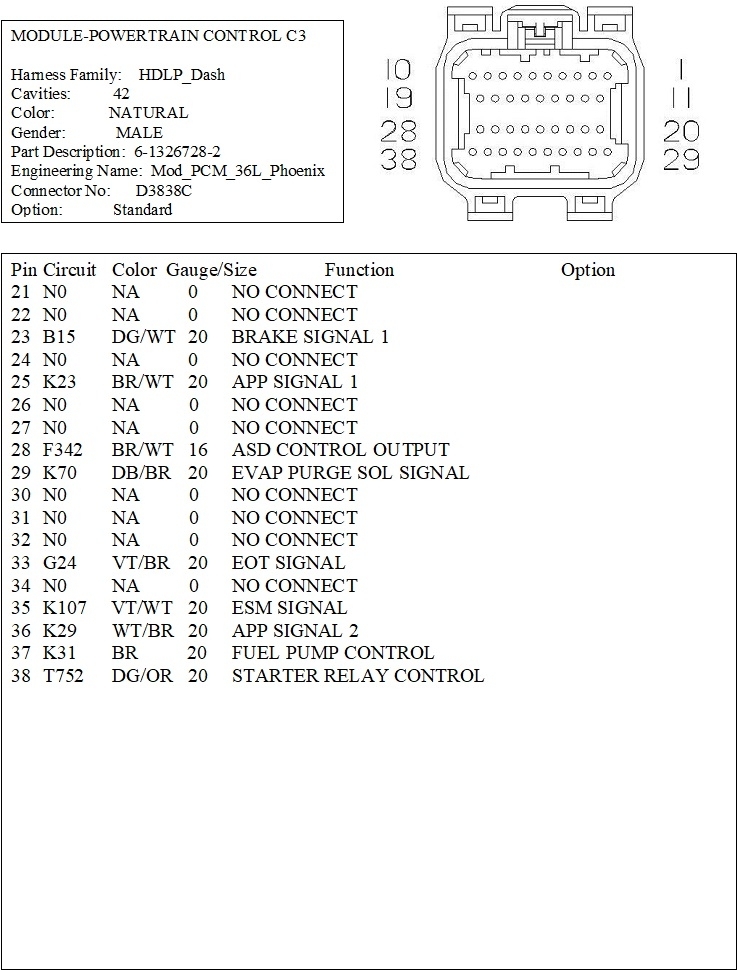
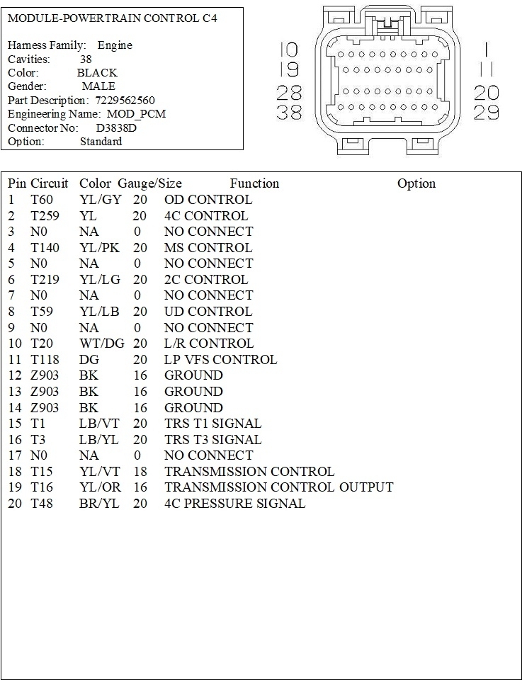
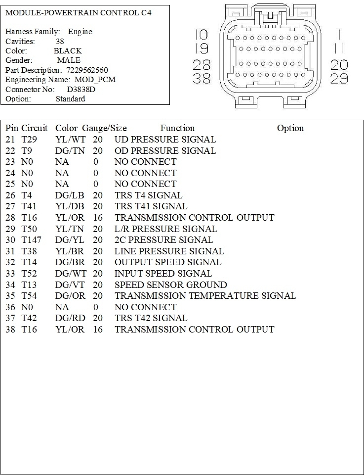
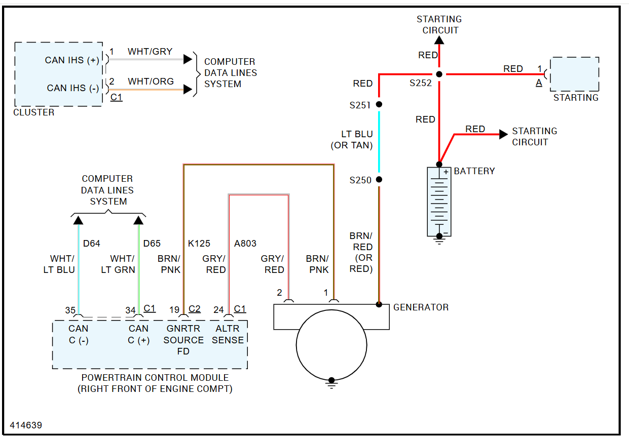
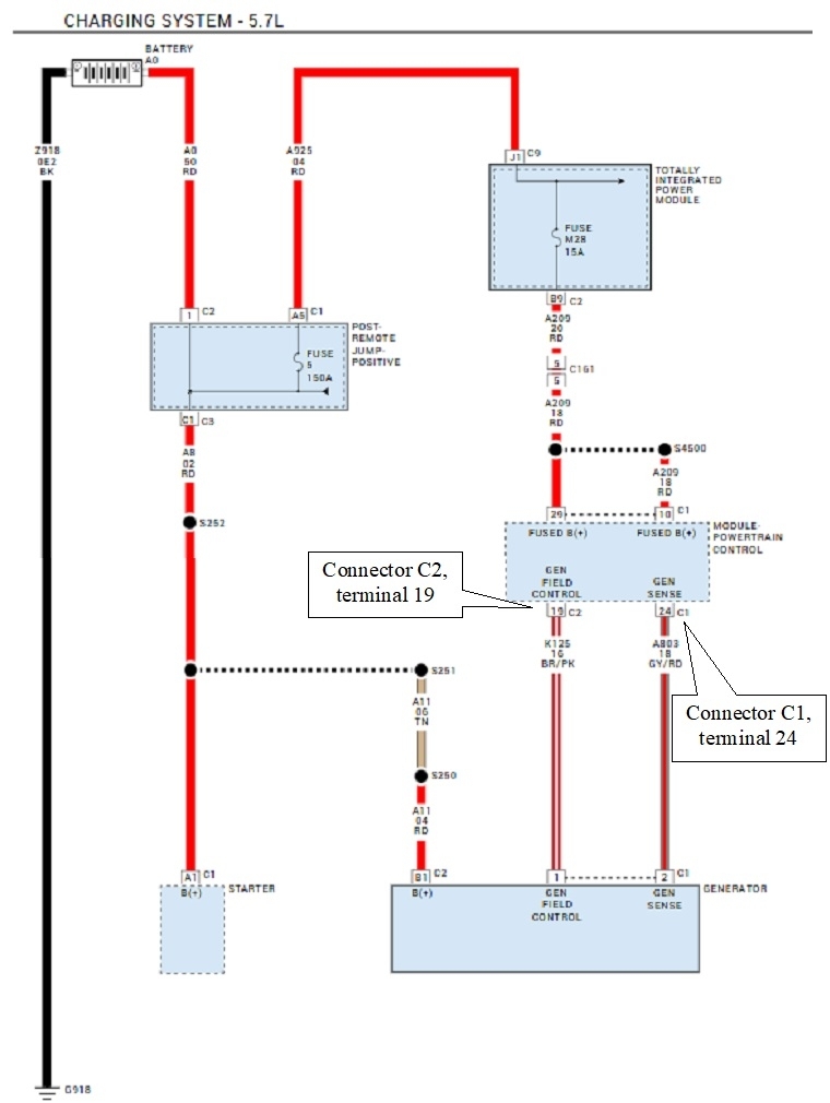
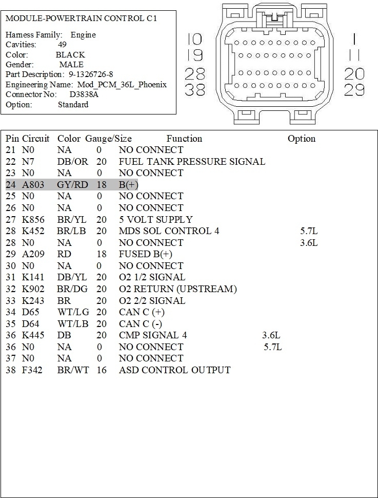
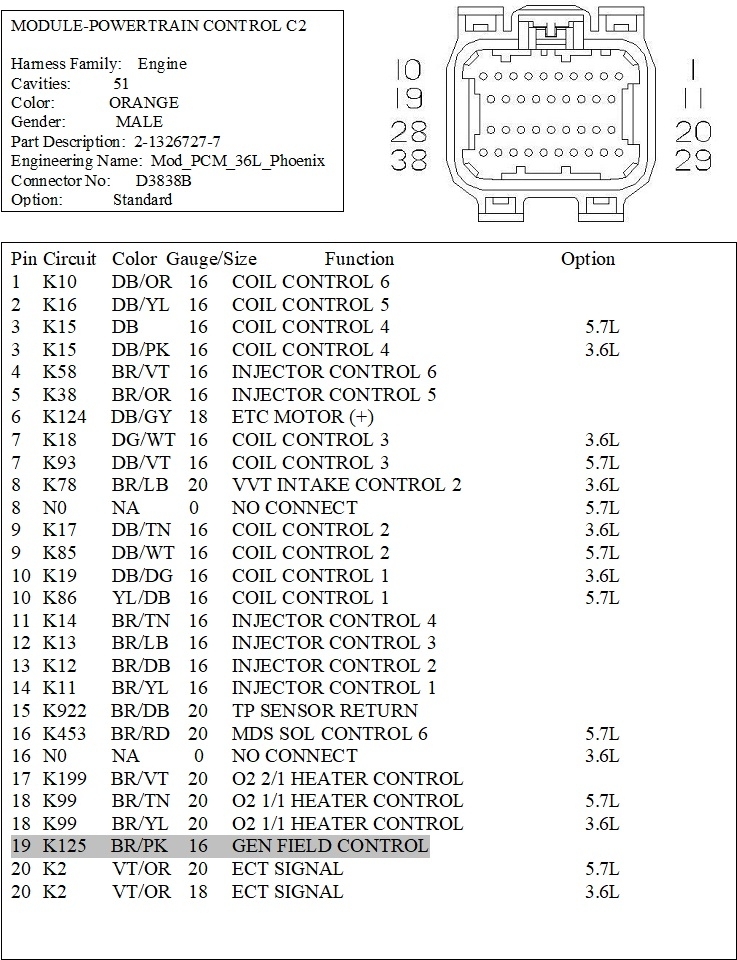
My vehicle listed above internal voltage regulator went out. Well, the previous owners just bypassed it and put an external regulator on there. I am having to go back to factory on the TIPM connectors because I bought a new computer. And I am confused where some of these wires go. I have a white and orange wire and a brown wire that goes into the C1 but don’t know which slot they go in? Someone please help!
Mar 3, 2025 at 12:44 PM
Advertisement
Avatar
CARADIODOC
  • CERTIFIED EXPERT
  • 34,306 POSTS
That's a fairly common modification. As with most innovations that directly benefit car owners over benefits to the manufacturers, Chrysler has led the way since the 1950s. Most notably, they developed the "AC generator" for 1960 models, and copyrighted the term, "alternator". They were also the first to have an electronic voltage regulator in 1970. It was a real popular unit for modifications. In fact, I'm using one on my New Holland skid steer to get its generator working again.

Here's the charging system diagram. The next two drawings are for the Engine Computer connector C1. Next two are for connector C2 etc.
Mar 3, 2025 at 1:37 PM
Avatar
STRAILER
  • CERTIFIED EXPERT
  • 53,854 POSTS
Besides the power wire, the other two wires go to the PCM. Here is the alternator wiring diagram so you can see how to rewire the system back to stock. Check out the images (below). Let us know if you need anything else.
Mar 3, 2025 at 1:38 PM
Advertisement
Avatar
CARADIODOC
  • CERTIFIED EXPERT
  • 34,306 POSTS
These are the same drawings, but for your purposes, I added two callouts to the diagram. These are the two wires you need at the Engine Computer, (PCM). The last two are the same wire lists for the two connectors, but I highlighted the two wires you need.

Let me know if I failed to cover something, otherwise let me know if you run into trouble.
Mar 3, 2025 at 4:34 PM