Hello -
Here is the info you requested.
CONTROL ARM
Removal
1. Raise and support front of vehicle. Remove front wheel.
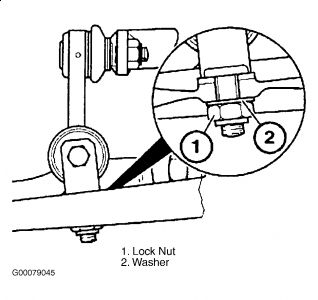
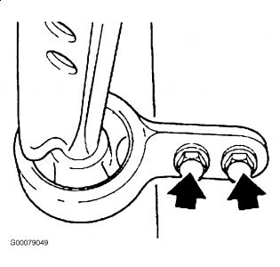
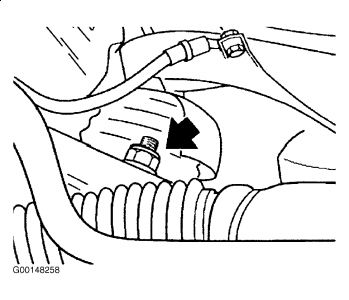
2. Disconnect stabilizer bar link from control arm. Release nut (1). See Fig. 9 .
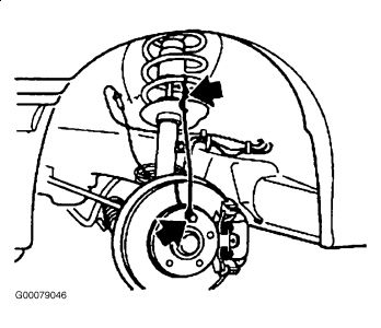
3. Install one wheel lug bolt and install a piece of wire from lug bolt to coil spring to prevent brake hose damage. See Fig. 17 .
4. Loosen nut until it contacts spring strut. See Fig. 18 .
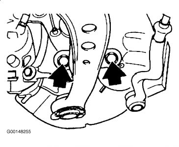
5. Remove 2 strut-to-steering knuckle bolts and discard. See Fig. 19 .
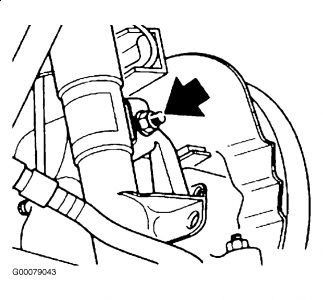
6. Remove upper strut-to-steering knuckle bolt and lock nut. Remove control arm-to-steering knuckle ball joint nut and discard. See Fig. 20 .
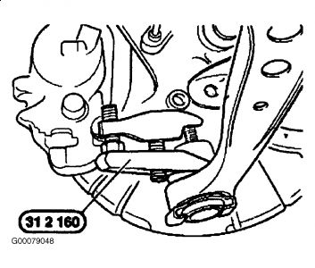
7. Using Ball Joint Separator (31-2-160), separate control arm-to-steering knuckle ball joint. Remove grease from bore and pin. See Fig. 21 .
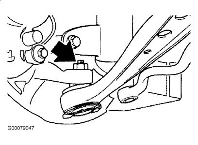
8. Remove tie-rod from control arm and suspend tie-rod aside. Remove control arm bracket-to-subframe bolts. See Fig. 32 .
9. Unscrew nut and knock ball joint loose with a plastic hammer. Remove control arm. See Fig. 22 .
10. Remove grease from bore and pin.
Installation
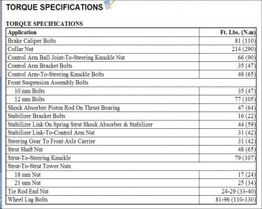
1. Force ball joint upwards using a transmission lifter and base. On vehicles with S52 engine, remove shield plates between manifold and wheel housing, if necessary. This simplifies the tightening down of the nut. Tighten to specification. See TORQUE SPECIFICATIONS .
2. Install control arm bracket-to-subframe bolts using washers and tighten to specification. See TORQUE SPECIFICATIONS .
3. Replace self-locking nut and install ball joint.
4. Replace self-locking nut and, using a shim on both sides, install upper strut-to-steering knuckle bolt.
5. Install 2 new strut-to-steering knuckle bolts.
6. Derust stub axle in area of contact face of rubber sleeve. Tighten nut to specification. See TORQUE SPECIFICATIONS .
7. Remove wire and wheel lug bolt.
8. Replace self-locking nut (1) and fit shim (2) for stabilizer connection on control arm.
9. Tighten nut to specification. See TORQUE SPECIFICATIONS .
10. Replace front wheel and tighten wheel lug bolts to specification. See TORQUE SPECIFICATIONS .
Oct 14, 2009 at 7:49 PM