No spark

1997 CHEVROLET SUBURBAN
200,000 MILES • 5.7L • V8 • 2WD • AUTOMATIC
Avatar
DAVISMELODY6669
  • MEMBER
  • 65 POSTS
SUV is a c1500. I checked in all connections and I have 12vs n ground.. new distributor new ignition coil and ignition module..all I did was upgrade camshaft.. replaced fuses in the fuse box n no spark.can anyone give me a clue where to check next please?
Dec 18, 2019 at 11:13 AM
Advertisement
Avatar
JACOBANDNICKOLAS
  • CERTIFIED EXPERT
  • 110,175 POSTS
Hi,

Have you checked the crankshaft position sensor? Make sure it is plugged in and there is no damage to the wiring. Also, if you have a live data scanner, see if there is an RPM signal when you crank the engine. If there isn't suspect the sensor may have been damaged when you had things apart.

I attached a pic of the sensor location below. Also, here are a few links you may find of interest:

https://www.2carpros.com/articles/how-a-crank-shaft-angle-sensor-works

https://www.2carpros.com/articles/symptoms-of-a-bad-crankshaft-sensor

https://www.2carpros.com/articles/crankshaft-angle-sensor-replacement

Let me know what you find or if you have other questions.

Take care,
Joe
Dec 18, 2019 at 8:47 PM
Avatar
DAVISMELODY6669
  • MEMBER
  • 65 POSTS
No rpm with live data..I did put in a new timing cover with new crankshaft sensor it feels loose with play I haven't put in shim to try and start it..
Dec 19, 2019 at 12:03 PM
Advertisement
Avatar
JACOBANDNICKOLAS
  • CERTIFIED EXPERT
  • 110,175 POSTS
Hi,

Okay. I suspect that is the problem. The sensor shouldn't be loose. Here is a link that explains common symptoms and one that explains how in general one is replaced.

Also, when you had the timing cover off, are you sure the reluctor ring was properly installed? See pic 4.

______________________________________

https://www.2carpros.com/articles/symptoms-of-a-bad-crankshaft-sensor

https://www.2carpros.com/articles/crankshaft-angle-sensor-replacement
_____________________________________
Here are directions specific to your vehicle.
'
1997 Chevy Truck C 1500 Suburban 2WD V8-5.7L VIN R
Crankshaft Position Sensor Replacement
Vehicle Powertrain Management Sensors and Switches - Powertrain Management Sensors and Switches - Computers and Control Systems Crankshaft Position Sensor Service and Repair Procedures Crankshaft Position Sensor Replacement
CRANKSHAFT POSITION SENSOR REPLACEMENT

pic 1
pic 2
pic 3


REMOVAL PROCEDURE
1. Remove the electrical connector.
2. Remove the sensor hold down bolt.
3. Remove the sensor from the timing cover.

NOTE: When installing or removing a crankshaft position (CKP) sensor make sure the sensor is fully seated and held stationary in the front cover before torquing the hold down bolt into the front cover. A sensor which is not seated may result in erratic operation and lead to the setting of false codes.

4. Inspect the sensor O-ring for wear, cracks or leakage. Replace if necessary. Lube the new O-ring with clean engine oil before installing.

INSTALLATION PROCEDURE

NOTE: Make certain that the Crankshaft Position (CKP) sensor mounting surfaces are clean and free of burrs before installing the CKP sensor.

1. Install the sensor into the timing cover.
2. Install the sensor hold down bolt.

Tighten
^ Tighten the hold down bolt to 8 Nm (71 lb in).

3. Install the electrical connector.

____________________________________________________________

Let me know what you find, if this helps, or if you have other questions.

Take care,

Joe
Dec 19, 2019 at 7:25 PM
Avatar
DAVISMELODY6669
  • MEMBER
  • 65 POSTS
I think I installed it right..I hope that's the problem something simple..I haven't tested the input signal with testlight or multimeter.
Dec 19, 2019 at 8:33 PM
Avatar
DAVISMELODY6669
  • MEMBER
  • 65 POSTS
I fixed the play on the crankshaft nice and tight and added one shim.. I did notice I have ground and power feed using a test light to the crank..but on coil I only have power feed no ground using the test light even while cranking..when I use the multi-meter I have 12v on both power n ground..
Dec 20, 2019 at 2:50 PM
Avatar
JACOBANDNICKOLAS
  • CERTIFIED EXPERT
  • 110,175 POSTS
Here is a test for the coil. Follow these directions and let me know the results. The attached picture correlates with the directions.

1997 Chevy Truck C 1500 Suburban 2WD V8-5.7L VIN R
Ignition Coil Test
Vehicle Powertrain Management Ignition System Ignition Coil Testing and Inspection Component Tests and General Diagnostics Ignition Coil Test
IGNITION COIL TEST

pic 1


IGNITION COIL TEST
^ Make sure the ignition switch is "OFF."

1. Disconnect the distributor lead and wiring from the ignition coil.

CAUTION: Do not Insert the J 39200 probe into the ignition coil connectors. The female terminals could be spread and deformed, resulting In intermittent operation of the coil. Be sure to make contact with only the front edge of the terminals.

2. Connect an ohmmeter as shown in Figure, step 1. Use the high scale. The reading should be infinite. If not, replace the coil.
3. Connect the ohmmeter as shown in Figure, step 2. Use the low scale. The reading should be 0.2 - 0.5 ohms. If not, replace the coil.
4. Connect the ohmmeter as shown in Figure, step 3. Use the high scale. The meter should read 5k - 25k ohms. If not, replace the coil.
5. Reconnect the distributor lead and wiring to the coil.
Dec 20, 2019 at 8:21 PM
Avatar
DAVISMELODY6669
  • MEMBER
  • 65 POSTS
The problem was the oil pressure switch and started up.. but now I have a bigger problem..I didn't degree the aftermarket camshaft..the motor didn't run right at all.. I turn it off n seen that the intake had white smoke..what is that?
Dec 20, 2019 at 8:56 PM
Avatar
JACOBANDNICKOLAS
  • CERTIFIED EXPERT
  • 110,175 POSTS
Hi,

As long as it wasn't backfiring through the intake, I wouldn't be too concerned. If it is, that's a different story.

Since degree wasn't adjusted with the aftermarket cam, the valves may not be fully seated causing the white smoke. Are you getting a backfire? As far as camshaft degree, with the different lifts on the new cam, timing is compromised. The point where lift begins and reaches peak requires manipulating engine timing in relationship to TDC. Keep in mind, when the engine was designed, it was designed for a specific cam lift for timing. When you chance that, you often times have to change how the camand crankshaft are timed in conjunction with each other. Interestingly, it is usually only a small number of degrees but that can make a big difference when it comes to performance.

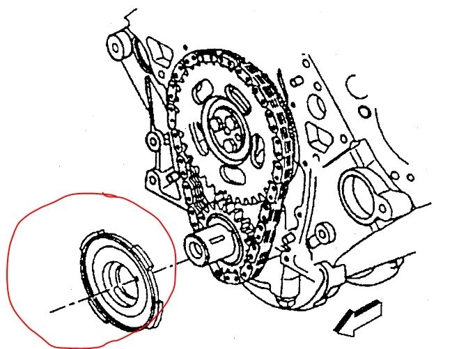
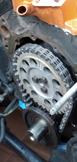
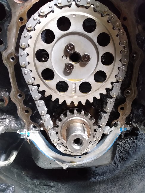
As far as the cam, did you have the engine completely taken apart? How much do you know about setting camshaft degree? It takes a bit of time, and to be honest, the only way I know how to do it requires the cylinder heads to be off to accurately reach TDC on the number 1 piston and then determine camshaft lift specs (which should be provided by the cam manufacturer) to get timing correct. I apologize for asking that question. For all I know, you may be better at it than me. I'm just trying to get an understanding of what you are comfortable with. Also, and I'm being honest, I question if I can explain it to you via a link.

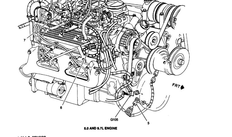
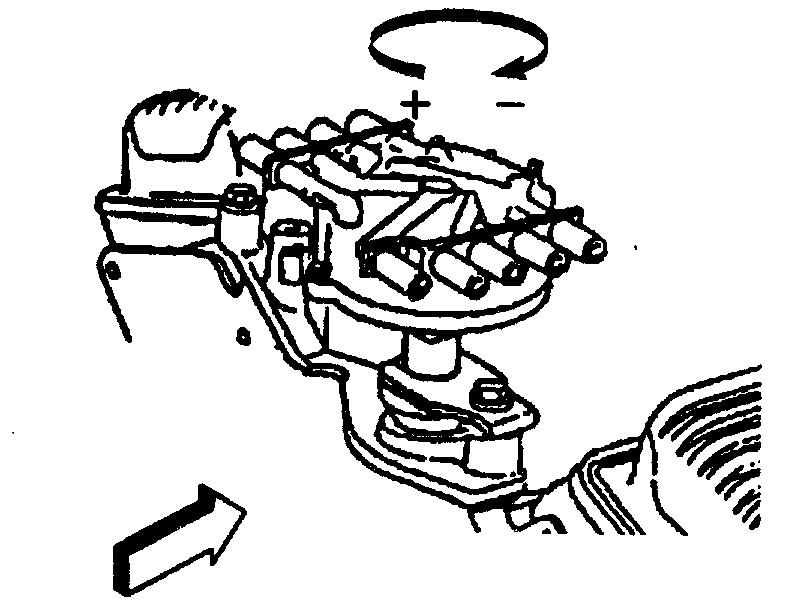
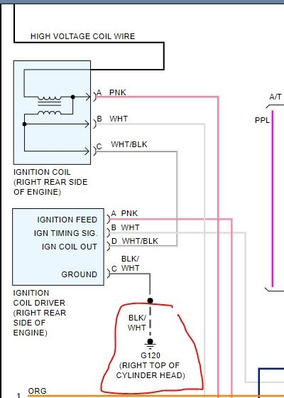
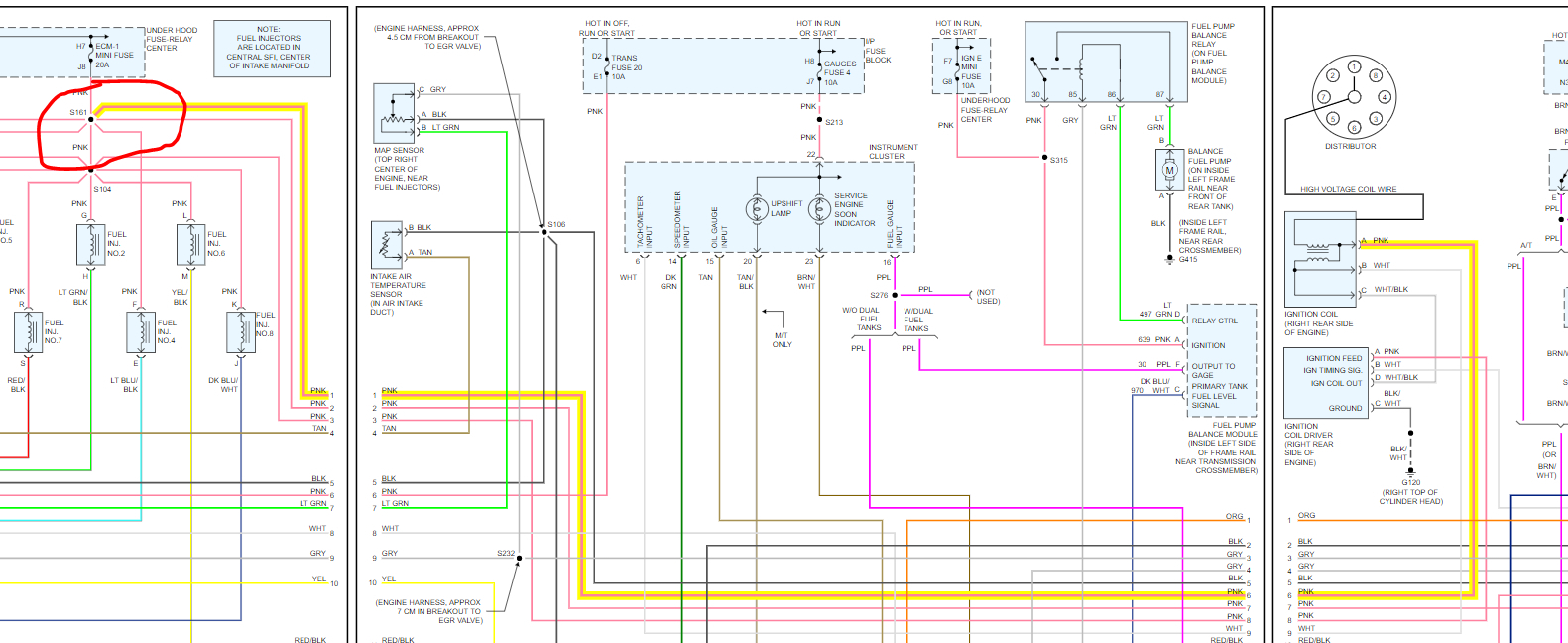
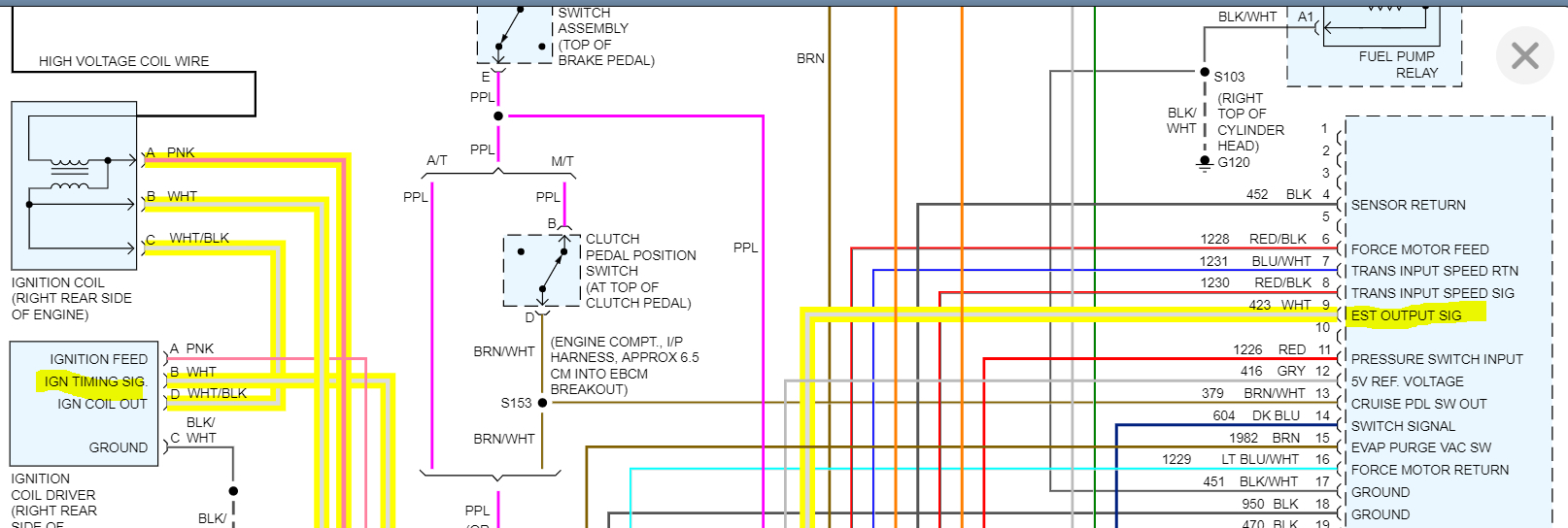
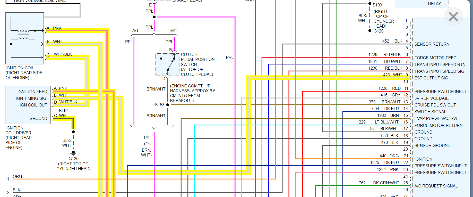
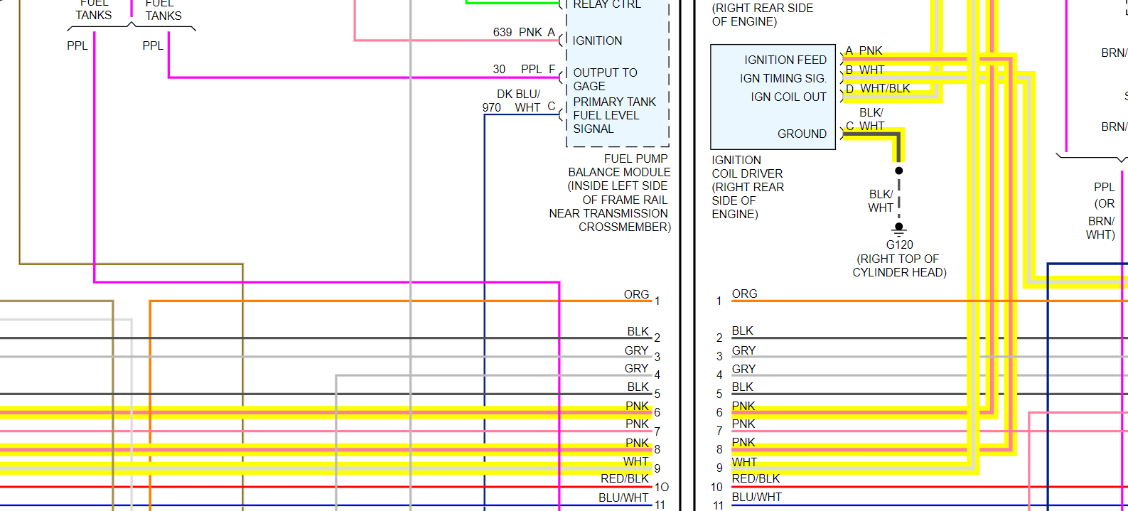
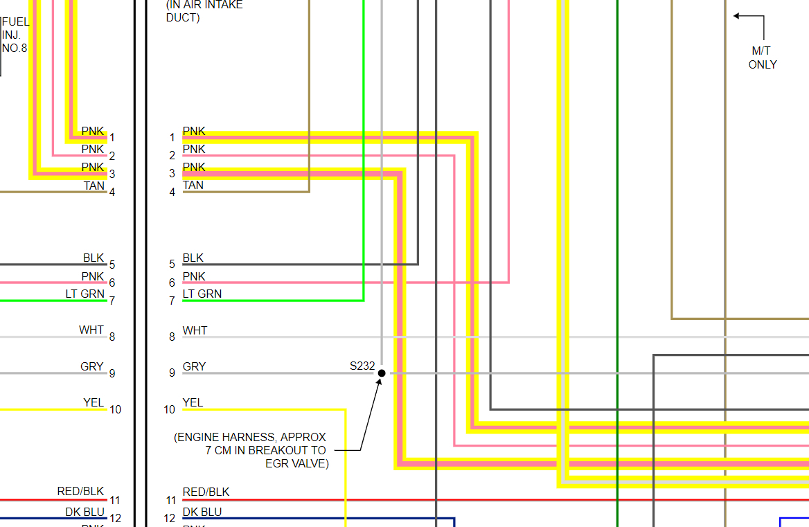
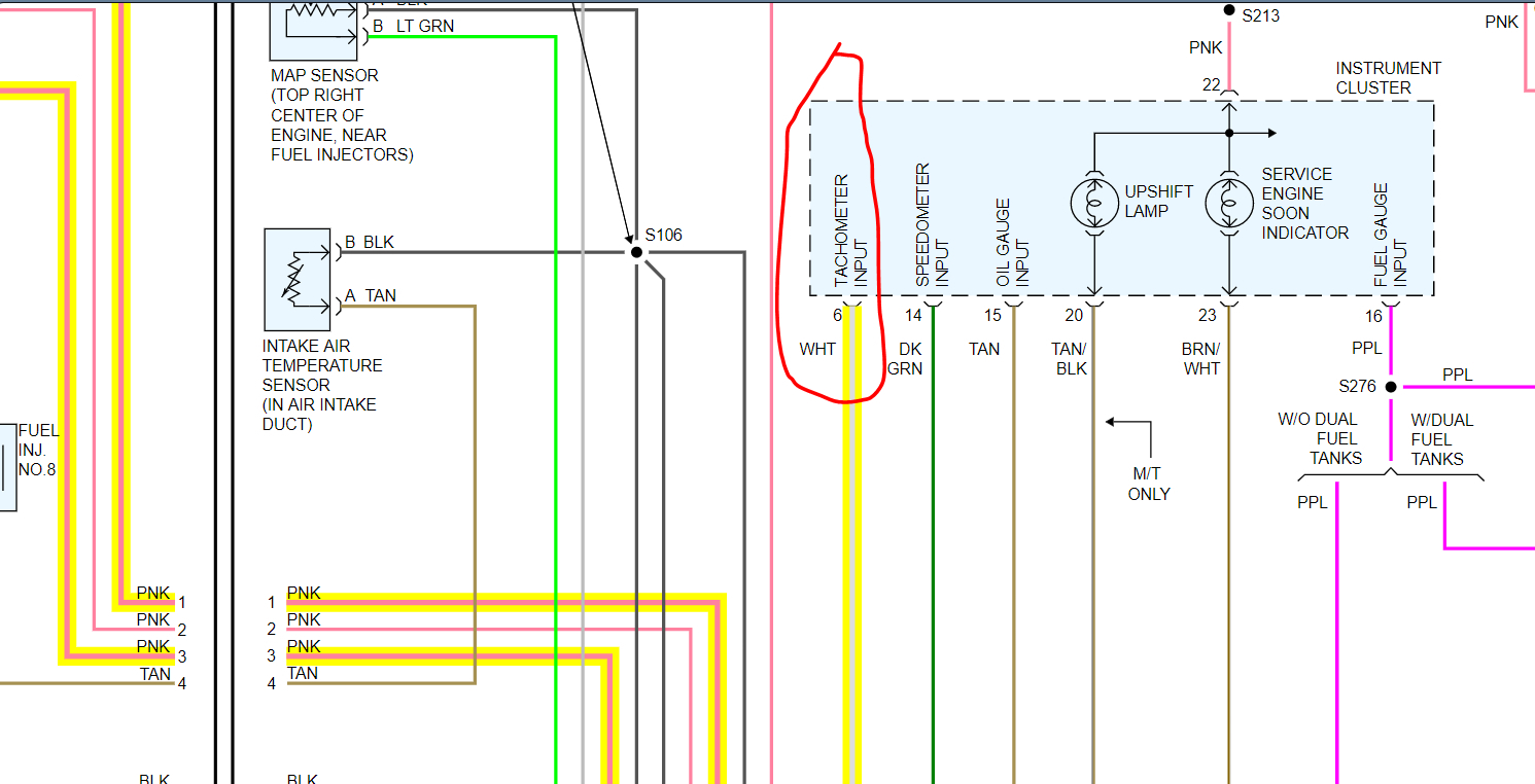
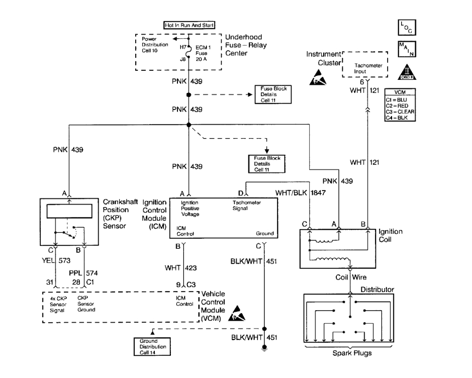
The ignition timing can't be changed without reprogramming the PCM. However, you can check the camshaft retard offset. Here are the directions, but I question if this is going to help. The attached picture correlates with these directions.

_____________________________________
1997 Chevy Truck C 1500 Suburban 2WD V8-5.7L VIN R
Camshaft Retard Offset Adjustment
Vehicle Powertrain Management Ignition System Ignition Timing Adjustments Camshaft Retard Offset Adjustment
CAMSHAFT RETARD OFFSET ADJUSTMENT

Description
imageOpen In New TabZoom/Print


TEST PROCEDURE
The ignition timing cannot be adjusted. The distributor may need adjusting to prevent crossfire. To insure proper alignment of the distributor, perform the following:

1. With the ignition OFF, install a scan tool to the DLC.
2. Start the engine and bring to normal operating temperature.

IMPORTANT: Cam Retard Offset reading will not be accurate below 1000 RPM.

3. Increase engine speed to 1000 RPM.
4. Monitor the Cam Retard Offset.
5. If the Cam Retard indicates a value of 0° +/-2°, the distributor is properly adjusted.
6. If the Cam Retard does not indicate 0° +/-2°, the distributor must be adjusted.


ADJUSTING PROCEDURE
1. With the engine OFF, slightly loosen the distributor hold down bolt.

IMPORTANT: Cam Retard Offset reading will not be accurate below 1000 RPM.

2. Start the engine and raise engine speed to 1000 RPM.

3. Using a scan tool monitor Cam Retard Offset.

4. Rotate the distributor as follows:
4.1.To compensate for a negative reading, rotate the distributor in the counterclockwise direction.
4.2.To compensate for a positive reading, rotate the distributor in the clockwise direction.

5. Repeat step 4 until 0° +/-2°, is obtained.

6. Turn the ignition OFF.

7. Tighten the distributor hold-down bolt to 3 Nm (25 lb. ft.).

8. Start the engine, raise engine speed to 1000 RPM and recheck Camshaft Retard Offset.

_______________________________________________

When you said it isn't running too good, can you describe what is happening or even upload a video of it running so I can hear it? Also, when cranking it, does it sound like a timing issue?

Let me know and again, sorry for so many questions.
Joe
Dec 21, 2019 at 10:34 PM
Avatar
DAVISMELODY6669
  • MEMBER
  • 65 POSTS
I installed the idle control valve n cranked over couple of times..I only here like two or three pops but this time no smoke.. I can't tell if it's back firing from the intake..at first I had paper n plastic bottles under the engine they flew away with the pressure of the headers..I noticed the fuel pump sounds weak.. maybe that's why it don't idle..the valve springs were installed to it's seat pressure due to the cam specs because it was all a kit.. n I want to remove the head to degree the can I have a wheel to do it.....how can I tell if it's back firing from the intake?
Dec 22, 2019 at 7:56 AM
Avatar
JACOBANDNICKOLAS
  • CERTIFIED EXPERT
  • 110,175 POSTS
If it is backfiring through the intake, you will hear it. Take a look through this link and see if it helps at all. Also, make sure the fuel pressure is within spec (not too low or too high).

https://www.2carpros.com/articles/engine-backfires-while-running

Let me know.

Joe
Dec 22, 2019 at 6:45 PM
Avatar
DAVISMELODY6669
  • MEMBER
  • 65 POSTS
I had the timing all wrong for doing it quickly. I do not know if it was 180 degrees advanced but I installed the cam swap dot to dot on to the intake stroke instead of the compression stroke.... Fuel pressure is correct it was just the timing.. it's better to double check the work always I hope this conversation helps others thank you either way JACOBANDNICKOLAS you're very helpful.
Dec 24, 2019 at 4:57 PM
Avatar
JACOBANDNICKOLAS
  • CERTIFIED EXPERT
  • 110,175 POSTS
I'm glad to hear you got if fixed. Honestly, that isn't a hard mistake to make. It happens. Regardless, please feel free to come back anytime you have questions. Also, I'm certain the thread you listed will help others. Thank you for that.

Take care and I hope you have a nice Christmas.

Joe
Dec 24, 2019 at 10:08 PM
Avatar
DAVISMELODY6669
  • MEMBER
  • 65 POSTS
I finally got the engine to turn one and idle fast and I gave it gas to 2 rpm for it to adjust the valve train. I noticed that the rpm was bouncing downwards.. I did change out the idle control valve... And now it doesn't want to start anymore. any idea you could help me out with?
Dec 27, 2019 at 4:45 PM
Avatar
DAVISMELODY6669
  • MEMBER
  • 65 POSTS
I have no spark again.
Dec 27, 2019 at 6:46 PM
Avatar
JACOBANDNICKOLAS
  • CERTIFIED EXPERT
  • 110,175 POSTS
If you crank it now with a live data scanner attached, do you have an RPM signal?
Dec 27, 2019 at 8:05 PM
Avatar
DAVISMELODY6669
  • MEMBER
  • 65 POSTS
I do have rpm signal on my gauge also I checked with the test light from the coil connection I have power feed but not the negative with key on while cranking.. the power feed light turns off while cranking.
Dec 27, 2019 at 8:48 PM
Avatar
JACOBANDNICKOLAS
  • CERTIFIED EXPERT
  • 110,175 POSTS
Check the ground on the rear of the cylinder head. Make sure it is in good condition and not damaged. See pic 1.

Joe
Dec 27, 2019 at 9:08 PM
Avatar
DAVISMELODY6669
  • MEMBER
  • 65 POSTS
I do have the ground bolt on the cylinder head 11v of ground.. on the ignition module connection I have power feed and ground with test light and key on.. am I supposed to have test light light up on the ground side of the coil connection? On the power feed side of the coil connection while cranking, the test light turns off or flickers off.
Dec 27, 2019 at 9:41 PM
Avatar
JACOBANDNICKOLAS
  • CERTIFIED EXPERT
  • 110,175 POSTS
It should not have power on the ground side If the light is turning off on the power feed side or flickering, you have a bad connection. There is a splice that may be bad in the wire to the coil. Also, if you look at pic 2, it shows the EST (electronic spark timing) signal wire. Are you getting a signal there?
Dec 27, 2019 at 10:38 PM
Avatar
DAVISMELODY6669
  • MEMBER
  • 65 POSTS
The light just gets little dim doesn't flicker.
Dec 29, 2019 at 3:22 PM
Avatar
DAVISMELODY6669
  • MEMBER
  • 65 POSTS
I have ground to the connection and control the test light, lights up and when i turn the key it turns off.. and I lost rpm signal. maybe the crank it's cutting off the spark because when it was idling it was almost dying because of the crank sensor.
Dec 29, 2019 at 3:39 PM
Avatar
JACOBANDNICKOLAS
  • CERTIFIED EXPERT
  • 110,175 POSTS
I hate to ask this again, but are you certain the ground is good? I have had situations where I would have continuity to ground but when a load was placed on it, it would fail.

Dec 29, 2019 at 6:06 PM
Avatar
DAVISMELODY6669
  • MEMBER
  • 65 POSTS
I checked all the wires that won't touch any ground and I have good ground. I checked everywhere around the motor.. I only checked the connection from the coil, power feed gets little dim and the control wire/ground wire lights on but turns off when key on using a needle with test-light. I guess I'm not understanding.
Dec 29, 2019 at 6:50 PM
Avatar
DAVISMELODY6669
  • MEMBER
  • 65 POSTS
I'm going to check the ignition switch harness.
Dec 30, 2019 at 10:17 AM
Avatar
JACOBANDNICKOLAS
  • CERTIFIED EXPERT
  • 110,175 POSTS
Let me know what you find. It's tough not being there. Regardless, I hope you have a good and safe new year tonight.

Take care,
Joe
Dec 31, 2019 at 7:36 PM
Avatar
DAVISMELODY6669
  • MEMBER
  • 65 POSTS
I checked the ground from the ignition module with test light even while cranking the light is strong..even the feed from coil n module but the control wire turns off the light when key is on..
Dec 31, 2019 at 8:15 PM
Avatar
DAVISMELODY6669
  • MEMBER
  • 65 POSTS
Thank you and you too. drink responsibly.
Dec 31, 2019 at 8:17 PM
Avatar
JACOBANDNICKOLAS
  • CERTIFIED EXPERT
  • 110,175 POSTS
I suspect then, the module is bad. Let me know when you get back to it.

Joe
Dec 31, 2019 at 8:51 PM
Avatar
DAVISMELODY6669
  • MEMBER
  • 65 POSTS
I did the swap for new ignition module today. Still the same.
Dec 31, 2019 at 9:03 PM
Avatar
JACOBANDNICKOLAS
  • CERTIFIED EXPERT
  • 110,175 POSTS
I attached the schematics from the coil to everything it goes to. There are a couple fuses I want you to check, but I have my doubts. Regardless, let me know which color wire at the loses power. I am trying to trace everything for you, but something just isn't making sense for me. Take a look. To follow all the wiring related to the coil, I had to go across several pages. As a result, there are several pics. I did highlight the wires involved. The pics end at the VCM. There is one section where I circled two fuses. I figured it wouldn't be a bad idea to check them as well as to confirm power.

__________________________________

Read through this description. Also, the last picture I attached is a GM schematic.

Circuit Description

The enhanced ignition system uses the crank sensor in order to provide the timing input to the VCM. The VCM uses this reference pulse in order to determine the individual ignition spark timing for each cylinder.

Once the VCM calculates the ignition timing, the ignition coil module on the IC circuit receives the timing signal. Each timing pulse received by the ignition coil module on the IC circuit triggers the coil module in order to operate the ignition coil. The secondary ignition voltage is induced, and then the secondary ignition voltage is sent to the distributor for distribution to each spark plug. This DTC is a type A DTC.

The IC signal voltage ranges from about 0.5 volt to 4.5 volts.

__________________________________

Next, I don't know if you have checked for trouble codes, but doing more research, I came across this. The flow chart for testing is in the last three pics. It seems relevant.

1997 Chevy Truck C 1500 Suburban 2WD V8-5.7L VIN R
P1361
Vehicle ALL Diagnostic Trouble Codes ( DTC ) Testing and Inspection P Code Charts


Circuit Description
The enhanced ignition system provides the timing input to the VCM with a crank sensor. The VCM uses this reference pulse in order to determine the individual ignition spark timing for each cylinder.

Once the VCM calculates the ignition timing, the ignition coil module on the IC circuit receives the timing signal. Each timing pulse received by the ignition coil module, on the IC circuit, triggers the coil module in order to operate the ignition coil. The secondary ignition voltage is induced, and then the secondary ignition voltage is sent to the distributor for distribution to each spark plug. This Diagnostic Trouble Code (DTC) is a type A DTC.

The IC signal voltage ranges from about 0.5 volt to 4.5 volts.

Conditions for Setting the DTC
EST enabled, and engine speed is less than 250 RPM.

Action Taken When The DTC Sets
The VCM turns on the Malfunction Indicator Lamp (MIL).

Conditions for Clearing the MIL/DTC
The VCM turns the MIL off after 3 consecutive driving trips without a fault condition present. A history DTC will clear if no fault conditions have been detected for 40 warm-up cycles (coolant temperature has risen 40°F from the start-up coolant temperature and the engine coolant temperature exceeds 160°F during that same ignition cycle) or the scan tool clearing feature has been used.

Diagnostic Aids
A poor connection, a rubbed through wire in the insulation, or a wire broken inside the insulation will cause an intermittent.

Check for the following conditions:

^ Poor connection.
^ Damaged harness: Inspect the VCM harness connectors for the following conditions:

- Backed out terminals GR9 and BK18.
- Improper mating.
- Broken locks.
- Improperly formed or damaged terminals.
- Poor terminal to wire connection.

And

- Damage harness.

^ Intermittent test If connections and harness check OK, monitor a digital voltmeter connected between VCM terminal GR9 and Bk18 while moving related connectors and wiring harness. If the failure is induced, the voltage reading will change. This may help to isolate the location of the malfunction.

Test Description
The numbers below refer to the step numbers in the diagnostic table.

2. If the engine starts at this point, the DTC 1361 is an intermittent.
3. This check determines if the IC signal from the VCM is available at the ignition coil module.
9. The remaining tests begins to check that the ignition coil module circuitry is OK. If the ignition coil module loses its voltage source, the secondary voltage will not be produced, and a DTC P1361 will set.

Let me know.

Joe
Dec 31, 2019 at 10:39 PM
Avatar
DAVISMELODY6669
  • MEMBER
  • 65 POSTS
The ECM didn't have good ground.
Jan 9, 2020 at 1:27 PM
Avatar
JACOBANDNICKOLAS
  • CERTIFIED EXPERT
  • 110,175 POSTS
Wow! I'm glad you got it going. If you page back through our conversations, that was one of my main concerns. You got tricked like I did with a false positive ground reading. That is so frustrating. I went through a similar situation with a no spark issue. I would check continuity to ground and it looked great, but once a load was placed on it, it failed.

No matter what, you did one heck of a job. These types of problems are difficult even for those who have a ton of experience. The fact that you found the issue says a lot.

Take care and let us know if you have questions in the future.

Joe
Jan 9, 2020 at 6:54 PM
Avatar
DAVISMELODY6669
  • MEMBER
  • 65 POSTS
Yes thank you for your patience and help.
Jan 11, 2020 at 6:18 PM
Avatar
JACOBANDNICKOLAS
  • CERTIFIED EXPERT
  • 110,175 POSTS
You are very welcome. I have to be honest, I enjoy a good challenge like this. Please let us know if you ever have questions in the future.

Take care of yourself.

Joe
Jan 11, 2020 at 8:22 PM