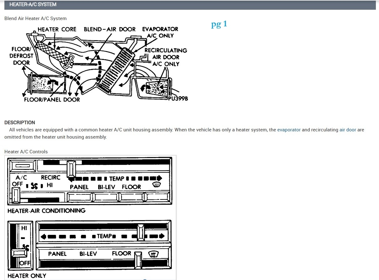
looking for temperature sensor parameters, vacuum solenoid pinout?

1990 CHRYSLER NEW YORKER
100,000 MILES • 2.5L • 4 CYL • 2WD • AUTOMATIC
Avatar
BARTOSZ PICHER
  • MEMBER
  • 8 POSTS
Hi,

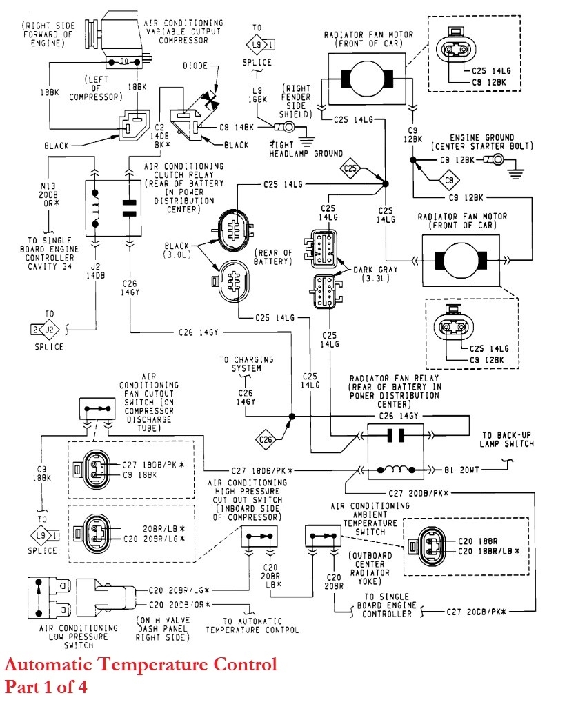
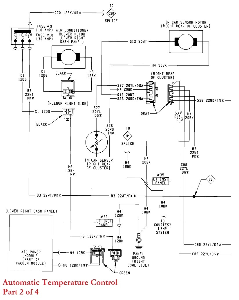
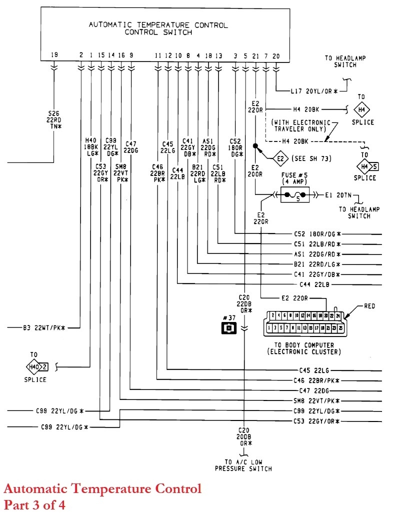
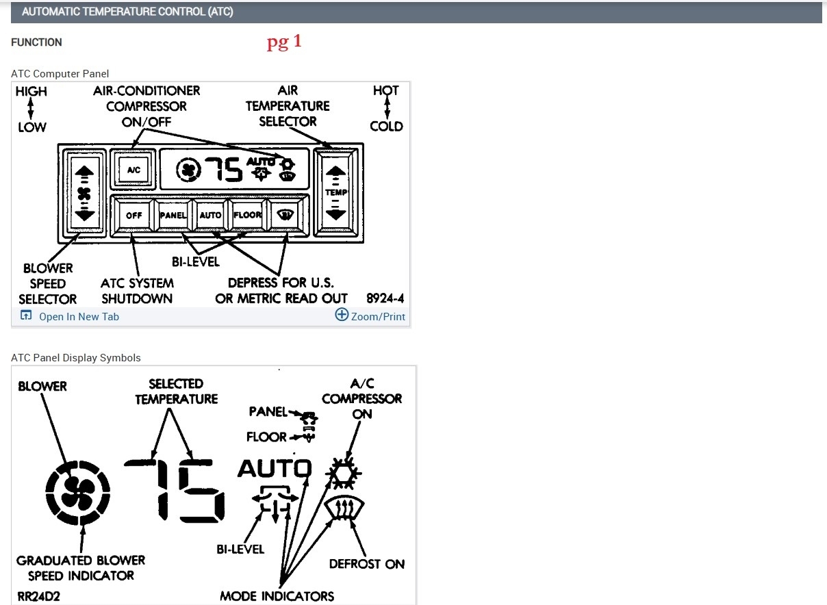
Looking for all technical info about ATC system from 90 Fifth Ave.

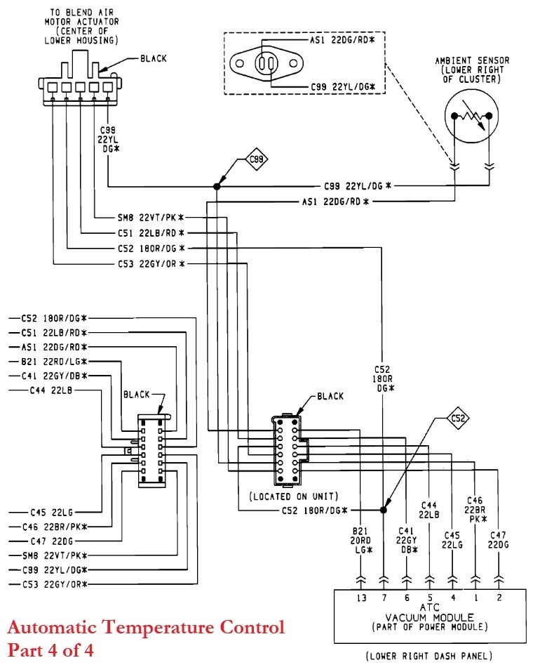
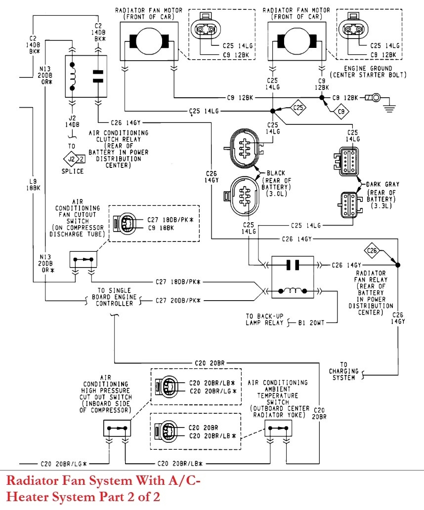
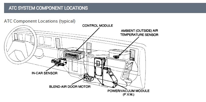
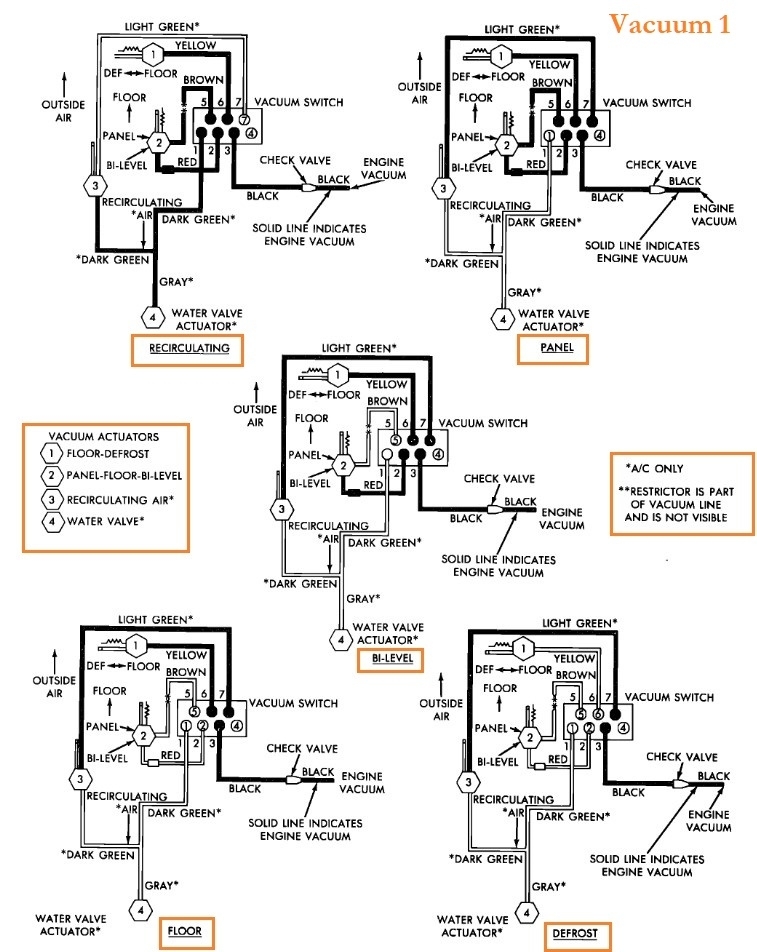
I would like to build that system to other Dodge model, looking for temp sensor parameters, vacuum solenoid pinout etc.

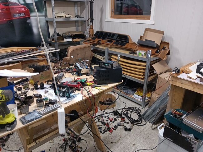
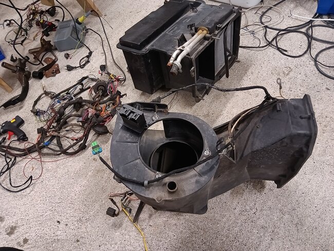
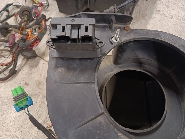
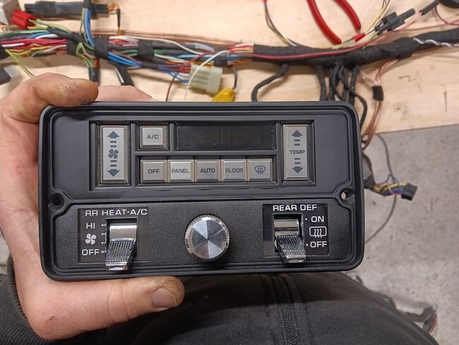
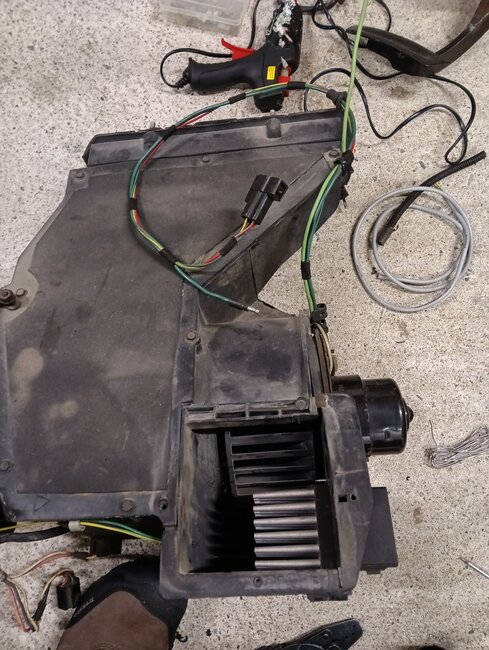
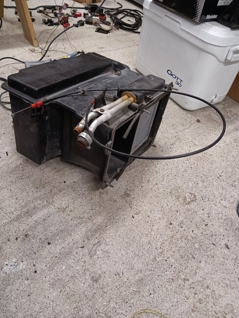
Today I have control panel (ATC control module) , plug with harness which self maked , temperature door servo.

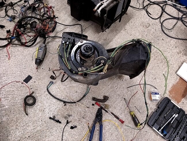
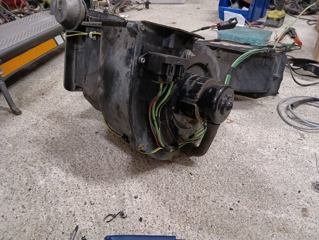
All system wired and connected as i found by logic , controll panel working and reacted for buttons, temperature door servo reacted and working , fan module converted from Jeep - that also working.

Need to know parameter from temperature sensor on car and more info about outside temperature sensor or switch ?

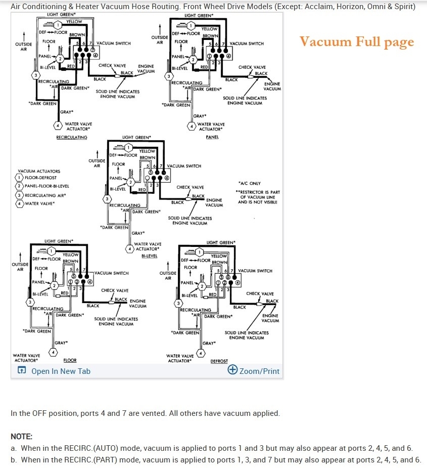
Also thinking about building self vacuum selenoid block - for that need more info or pictures.

Jan 3, 2025 at 8:47 AM
Advertisement
Avatar
AL514
  • CERTIFIED EXPERT
  • 5,464 POSTS
Hello, there are 7 wiring diagrams in total that are listed for different system types, I'll just post them all and you can go through and see what wire colors you have, there is also a vacuum diagram with the solenoid block that shows the different routes vacuum would be applied for panel, defrost, floor, etc. I'll post that as well. These older diagrams can be somewhat limited, but it sounds like you have an idea of what you're doing, ill also search for any additional info on the temperature sensors, there are a couple different ones. But they should use a 5volt reference I'd think, just as temperature sensors do now. So unplugged you would read 5volts on one of the temperature sensors 2 wires, then plugged in the resistance of the sensor would pull the voltage lower for a signal back to its control module.
Jan 3, 2025 at 2:16 PM
Avatar
BARTOSZ PICHER
  • MEMBER
  • 8 POSTS
Hi Man,
Thank you for answer.

Inside temperature sensor already matched with right value, but don't have any idea how to find outside temperature sensor value ....
Vacuum solenoid block can build by myself, found signals from atc controller.
Jan 3, 2025 at 2:34 PM
Advertisement
Avatar
AL514
  • CERTIFIED EXPERT
  • 5,464 POSTS
On most outside Ambient temperature sensors, they usually show up on the Cluster once the key is On. Or there is a small display somewhere on the dash. Because I don't see any outside temp reading on the ATC display panel, I'll post all the information I found so far, it does show the location of the Ambient outside temp sensor, the temp sensor in the vehicle is labelled as "In-Car Sensor". But there's 16 pages so far you can go through.
Jan 3, 2025 at 2:50 PM
Avatar
BARTOSZ PICHER
  • MEMBER
  • 8 POSTS
Can you measure for me that sensor at 3 different point of temperature?
That give to clear answer for choose right type.
Jan 3, 2025 at 2:56 PM
Avatar
AL514
  • CERTIFIED EXPERT
  • 5,464 POSTS
Here's all the wiring diagrams, operations, a diagnostic flow chart, the ATC display and the Vacuum routing diagrams. I'll look for the outside temperature display location as well but see if any of this helps.
Jan 3, 2025 at 3:00 PM
Avatar
AL514
  • CERTIFIED EXPERT
  • 5,464 POSTS
If you're looking for a resistance value per temperature, I would think on an older vehicle like this the inside temperature sensor is probably the same resistance. The only temp sensor that might be different that reads air temperature would be the intake air temperature sensor, since that reads air being drawn into the engine and is in a much different environment. But an ambient temperature sensor for a display on this is most likely going to be the same resistance value as the In-Car, I didn't see any different part number for those 2 sensors, the coolant temp sensor is a different story, those cannot read air temperatures correctly, they are designed for coolant readings only.
Jan 3, 2025 at 3:11 PM
Avatar
BARTOSZ PICHER
  • MEMBER
  • 8 POSTS
Excellent, do you have fault code chart as well?
Jan 3, 2025 at 3:16 PM
Avatar
AL514
  • CERTIFIED EXPERT
  • 5,464 POSTS
I will check on that right now.
Jan 4, 2025 at 10:58 AM
Avatar
AL514
  • CERTIFIED EXPERT
  • 5,464 POSTS
Sorry for the delay, they had a page for each code, but check out pages 14 and 15, it shows the resistance value of the temperature sensors at different temperatures.
Jan 4, 2025 at 11:49 AM
Avatar
BARTOSZ PICHER
  • MEMBER
  • 8 POSTS
Hello,

First of all - big respect for you.
Many thanks for your help and time spent on that, all what I am looking for is there.

If you need any help from my side - just write.

Regards from man from Poland at Norwegian arctic circle.

Jan 4, 2025 at 12:26 PM
Avatar
AL514
  • CERTIFIED EXPERT
  • 5,464 POSTS
Glad to help, Poland huh. Well, keep warm up there. We get people from all over the world, it is always interesting to hear where they are from. Hope your build goes well.
Jan 4, 2025 at 12:44 PM
Avatar
BARTOSZ PICHER
  • MEMBER
  • 8 POSTS
System working well, no faults after diagnostic test.
Today I was done with a new harness to blower speed control module and outside temperature sensor.
Speed control module placed be side blower wheel, temperature sensor decided placed on fresh air/outside air intake duct to blower.
Connector from 80's and wire color code matching.
Working with temperature blend door actuator - like using original wire from that door with connection on case when need comeback to manual version, so must make arm and holder conversion to blend door actuator.
Jan 4, 2025 at 2:49 PM
Avatar
AL514
  • CERTIFIED EXPERT
  • 5,464 POSTS
Gotta be creative sometimes like this. I know I end up building my own testing equipment sometimes when I don't want to spend a thousand dollars. But I hope for the best for you.
Jan 4, 2025 at 2:54 PM