Alternator not charging?

2009 DODGE RAM
2,000 MILES • 5.7L • V8 • 2WD • AUTOMATIC
Avatar
TGWILSON13
  • MEMBER
  • 5 POSTS
I have a 2009 Dodge Ram and it will not charge I have put a brand new alternator battery and replaced the PCM and still it won't charge
Nov 16, 2015 at 1:44 PM
Advertisement
Avatar
CARADIODOC
  • CERTIFIED EXPERT
  • 34,306 POSTS
Measure the voltages on the three wires on the alternator. The large output wire should have battery voltage on it of 12.6 volts with the engine stopped, and it should go up to 13.75 to 14.75 with it running. The voltages on the two small terminals have to be taken with the engine running. Remember that these newer trucks see the battery is charged and allow the alternator to "let off" on the charge to save gas and not to overheat the battery. Here is the alternator wiring diagrams so you can see how the system works. Check out the diagrams (Below). Let us know what happens and please upload pictures or videos of the problem.


Nov 16, 2015 at 2:22 PM
Avatar
TGWILSON13
  • MEMBER
  • 5 POSTS
The 2 wires on top are the voltage regulator to the PCM right
Nov 16, 2015 at 8:31 PM
Advertisement
Avatar
CARADIODOC
  • CERTIFIED EXPERT
  • 34,306 POSTS
Nope. Building the voltage regulator into the generator, like GM and Ford do, insures you have to buy more than what must be replaced. Chrysler never did that. The voltage regulator is inside the Engine Computer where it can adjust charging voltage or turn the alternator off based on air temperature, coolant temperature, wide-open-throttle, and anything else the computer knows. This makes their alternators real simple and the circuit is easy to test.
Nov 17, 2015 at 4:14 PM
Avatar
TGWILSON13
  • MEMBER
  • 5 POSTS
I checked the volts and they are ok but when I turn it on it stays at 12.1 volts and says it's not charging and I have replaced the alternator battery and PCM still they won't charge
Nov 17, 2015 at 5:36 PM
Avatar
CARADIODOC
  • CERTIFIED EXPERT
  • 34,306 POSTS
You gotta be more specific so I can figure out what's working and what isn't. What are you turning on and what stays at 12.1 volts? What are the three voltages on the alternator wires when the engine is running?
Nov 17, 2015 at 7:30 PM
Avatar
TGWILSON13
  • MEMBER
  • 5 POSTS
Ok I re check the connections in on top of the alternator there is a red wire in a black wire the black wire gets 12 volts but the red wire has nothing and the big wire that goes to the alternator reads 11.9 volts.
Nov 18, 2015 at 12:14 PM
Avatar
CARADIODOC
  • CERTIFIED EXPERT
  • 34,306 POSTS
The two small wires won't have voltage until the engine is running. I need to know what you find on them when the engine is running. In particular, the brown / gray wire has to have something, but I haven't worked on this new system so I don't know if it's a voltage or a square wave pulse. If you find 0 volts with a digital voltmeter, or if the reading is bouncing around, check it with a test light. According to what I've been reading, this is the only control wire so you'll rarely find full battery voltage on it, if ever. A digital voltmeter will get confused with a pulsing square wave, but a test light will smooth it out and give you a better indication. I think the light should be dimmer than when it's connected to the battery.
Nov 23, 2015 at 6:46 PM
Avatar
TGWILSON13
  • MEMBER
  • 5 POSTS
Okay I looked at the wiring diagrams and got a new TIPM that fixed it thank you so much!
Nov 24, 2015 at 8:09 PM
Avatar
DODGE2500
  • MEMBER
  • 1 POST
I bypassed the PCM with adjustable external voltage regulator. New alternator and new battery. I have 12v to the alternator but alternator still wont charge. I had a broken engine ground strap from back of cylinder heads and replaced it. Cleaned all grounds I can find.
Jun 23, 2021 at 6:47 PM (Merged)
Avatar
SCGRANTURISMO
  • CERTIFIED EXPERT
  • 4,897 POSTS
Hello,

What do you mean you have 12V to alternator? The alternator is what charges the battery. In the diagrams down below I have included a wiring diagram of your vehicle's charging system for reference purposes. Here are a couple of links for you to go to:

https://www.2carpros.com/articles/how-to-check-a-car-alternator
https://www.2carpros.com/articles/car-battery-load-test

Please go through these guides and get back to us with what you are able to find out.

Thanks,
Alex
2CarPros
Jun 23, 2021 at 6:47 PM (Merged)
Avatar
UNORTHODOX91
  • MEMBER
  • 4 POSTS
No fluff.
Truck has 3rd generator on it, no charge. Battery voltage present on Gen Bat+, Bat+, and TIPM post.
Checked all wiring at PCM pins to connectors, and did voltage drop test across the power supplies.
The only discrepancies i'm seeing are:

1) Gen sense terminal on gen is showing Batt voltage, parallel to Gen Post. But when the 2-pin connector is connected and back probed, voltage is 9v. Confirmed 3v voltage drop across Batt+ and pin-2 (red/grey).
I suspected resistance in wire but continuity checked out. I pull off PCM connector and turned key on and observed the same 9v coming from the PCM male pin corresponding to pin-2. I checked pin-10 and pin-29 as they’re fused bat+ feeds and I’m getting Bat+ voltage at the connector. Are my suspicions of resistance in the PCM causing the 3v drop? Or is it getting 9v from somewhere and spitting it back out? No info online on PCM voltage specs.

2) Pin-1 is the Gen field control. The PCM uses pwm/square waves to activate field. When I tried to measure duty cycle with my dmm, I would get sporadic duty readings, never holding for more than 2 seconds. When I tried to live test the Gen duty cycle via scan tool(key on engine off) I would set duty cycle to 50% and would read sporadic readings across the range. Unsuccessful bypass with pin-1 (br/gy) to bat negative.

Scan tool states duty cycle @ 100% while running, but Gen Post pushing batt+ voltage. Target voltage is at 14.3v.
Jun 23, 2021 at 6:48 PM (Merged)
Avatar
KASEKENNY
  • CERTIFIED EXPERT
  • 18,907 POSTS
I am not sure I understand where you are finding the 3 volt drop. Is this on the wiring or are you saying you are finding this internal to the PCM?

The reason is, this generator sense circuit is what the generator sends back to the PCM so the PCM can compare that to the B+ it is getting from the TIPM. When they are not the same it commands the regulator to increase the voltage.

Sounds like the PCM (regulator which is internal to the PCM) is not able to command the voltage to increase.

Let me know if I am not understanding where you are checking this voltage. However, the fact that you have 9 volts on the sense circuit is where your issue is.
Jun 23, 2021 at 6:48 PM (Merged)
Avatar
UNORTHODOX91
  • MEMBER
  • 4 POSTS
Hello and thank you for your response.

To clarify, I am picking up the 9v in the wiring, but if I recall correctly, I also disconnected connector-1 of the PCM, turned the key to the "on" position, and measured 9v from pin-24, which corresponds to the Gen sense. Which is kind of odd since the B+ connections go thru connector-1.

Anyhow, today I searched for a 5v reference off the throttle body and only picked up mV's. I then proceeded to back probe the connectors and performed a voltage drop test on all B+ and grounds going to the PCM...nothing but that 9v discrepancy showed.

It's an odd situation since it seems as though the computer is detecting the low voltage and is trying to push 100% duty on the field, but cant signal to the gen put out the target 14.3v.
I'm banging my head trying to avoid making an assumption on the PCM, but it keeps looking like the culprit.

Testing performed:
-Continuity
-Voltage Drop
-Tracer (power probe etc)
-Gen by-passing (ineffective)
-5v reference
-Scan tool (live data & live test)
-Duty cycle measurements on Gen connector
-visually inspected and wiggled Batt cables, grounds, and wiring (accessible ones).
-Powertrain verification test
-Transmission verification test
-Changed pigtail since the prior would lock the red tab.
Had to keep charging battery since it would run down to 7v @ 100% duty cycle..it makes no sense!

I haven't opened the wiring harness to investigate if the suspected wire is causing the issue since I performed a continuity test and power probe etc tracer through it. But I feel like that's the only stone left unturned.
Jun 23, 2021 at 6:48 PM (Merged)
Avatar
KASEKENNY
  • CERTIFIED EXPERT
  • 18,907 POSTS
If all your B+ are 9 volts it sounds like you may have a ground issue. You can check and clean the grounds but to confirm this, you can just back probe the grounds with a safety pin and run them to the closest stud on the engine block just to test this. It will take the easiest path to ground so if there is a ground issue, this will clear it up and then you will be able to track down the issue.
Jun 23, 2021 at 6:48 PM (Merged)
Avatar
UNORTHODOX91
  • MEMBER
  • 4 POSTS
I went through all 4 connectors and voltage drop tested all the B+ and grounds. All grounds were good and the B+ wires showed battery voltage as intended, but the only 9v is coming from the gen sense. No other circuit is showing 9v. I’m also not showing a 5v reference on the throttle body connector. I already ordered the PCM # RL150390AE.
Jun 23, 2021 at 6:48 PM (Merged)
Avatar
KASEKENNY
  • CERTIFIED EXPERT
  • 18,907 POSTS
I think you nailed it. Let us know what happens after you get the PCM in there. Thanks for the update.
Jun 23, 2021 at 6:48 PM (Merged)
Avatar
KURTIS WEST
  • MEMBER
  • 2 POSTS
Truck listed above is the 1500.

Started off with a intermittent blower motor. Figured it was the resistor so I replaced that. However, today intermittent issue happened again. Smacked blower and it kicked on.

This is the issue though, when the blower is set to max the voltage gauge goes from a click above half which I believe is 13 or 14v to just below half. When it does this my lights dim, motor slows down and rpm's drop.

I'm believing that the blower motor is bad and needs to be replaced. BUT starting today the voltage is staying just barely above half and at a stop it will try to dip to half or below even with blower off.

Had O'reillys, AutoZone and Advanced Auto all test my battery, alternator and starter.

Battery came back at 12.3.
Alternator came back at 14.5 and apparently diodes and regulator got a green light.
Starter is good as its brand new.

Could the blower even while off be causing a parasitic draw on the battery?
Can the alternator state it's good but is actually going out while driving?

About a week ago I had a dtc that read voltage below 13 while above 2,000 rpm's.
Which I would assume it means while under load and driving the running volts dipped below 13.

Any help would be appreciated. I know I stated a lot but i wanted to help describe the situation as in depth as possible as it's hard to diagnose via online.
Jun 23, 2021 at 6:48 PM (Merged)
Avatar
CARADIODOC
  • CERTIFIED EXPERT
  • 34,306 POSTS
The most common alternator failure is worn internal brushes, and those always start out as an intermittent no-charge problem that gets progressively worse over weeks and months. The brush assembly can be replaced for around $12.00. The next most likely suspect is a break in the field wire between the Engine Computer and the alternator. These can be found with voltage tests, but to be valid for diagnosing this, those readings have to be taken while the problem is occurring.

The heater fan motor won't have any effect on this when it's turned off, and from what you described, the best suspect is worn brushes in that motor. Hitting it and it starts running is the big clue there. I'm working with another fellow for the same problem right now. His looks like it's going to be related to overheated connector terminals on the back of the HVAC controller, but his symptoms are a little different too.

Engine idle speed can be affected by an intermittent charging system. When it cuts out, system voltage drops, and that is the voltage applied to the injectors. With less voltage across them when the computer pulses them open, it will take a little longer for their valves to be pulled open, so you'll get less gas. If this condition lasts long enough, the computer will pulse the automatic idle speed motor to get idle speed back up, and you'll see short-term fuel trim numbers increase to get the volume of fuel back up to where it should be.

If you can catch the charging problem acting up, measure the voltages on the two smaller terminals on the back of the alternator and tell me what you find. These must be taken with the engine running. It would also be helpful if you can see what those voltages are when the system is charging normally.
Jun 23, 2021 at 6:48 PM (Merged)
Avatar
UNORTHODOX91
  • MEMBER
  • 4 POSTS
Update:

So after running the aforementioned tests, I concluded that the PCM’s voltage regulator had failed, and required replacement.
I ordered a new PCM from mopar (part # RL150390AE). I soon learned that trying to “program” a pcm via scan tool was a futile venture.Being my first new PCM, it took me a while to determine that it required a flash of the corresponding vehicle file from TechAuthority via WiTech 2.0 (j2534).
After flashing the PCM and performing relearns, the truck started right up and the generator was pushing 14.3v! Success!

Hope this provides insight for anyone else dealing with the same issue.
Thanks for the input and boost in confidence venturing in unknown territory.
Jun 23, 2021 at 6:48 PM (Merged)
Avatar
KURTIS WEST
  • MEMBER
  • 2 POSTS
So I noticed some minor burns on the fusible link so I replaced it now it charges thanks
Jun 23, 2021 at 6:48 PM (Merged)
Avatar
KASEKENNY
  • CERTIFIED EXPERT
  • 18,907 POSTS
Not only did you give us good info on the correction but you included all the OEM/aftermarket tool info needed to get it updated. That is a great update.

Thanks for the info and using 2CarPros
Jun 23, 2021 at 6:48 PM (Merged)
Avatar
RAM5
  • MEMBER
  • 2 POSTS
While driving home the check gauges light came on and I noticed the voltmeter went to "zero". Made it home, shut down and restarted. Gauge dropped to zero and light came on. Next day started truck and gauge showed charging with no warning light on. I checked voltage at battery (running) which was 14. 4. Shut down truck and checked across battery posts and got 12.7V. Went on to clean terminals/posts. Restarted and left running till the truck temp had heated to normal and again found alt was charging at 14+ volts. The following day took a trip to town with no problems however after shutting off truck and restarting to return home the check gauges light came back on and the voltmeter went to zero. Got home and check voltage at the battery (running) at 11.8V. I'm not sure if this is an alternator problem or not. Thank you for any help you can give.
Jun 23, 2021 at 6:48 PM (Merged)
Avatar
HMAC300
  • CERTIFIED EXPERT
  • 48,601 POSTS
check two items in pic if not those then have it scanned for codes it may be a tpim module problem.
Jun 23, 2021 at 6:48 PM (Merged)
Avatar
RAM5
  • MEMBER
  • 2 POSTS
Thank you. I did replace the alternator over the weekend after finding the brushes on the old one significantly worn down to the point where one of them looked like it could be making intermittent contact. all fixed.
Jun 23, 2021 at 6:48 PM (Merged)
Avatar
BSPEEDO77
  • MEMBER
  • 2 POSTS
The alternator on my 04 dodge ram does not charge the battery. I have replaced to alternator and the battery. i have also changed the fusible link that is between the alternator and battery.I have checked the cable that goes from the B+ terminal on the alt. to the battery with a circuit tester and it is good. I have also checked the 3 ground wires off the negative post of the battery and can't find anything wrong with them. Please help.
Jun 23, 2021 at 6:48 PM (Merged)
Avatar
CARADIODOC
  • CERTIFIED EXPERT
  • 34,306 POSTS
Hi bspeedo77. Welcome to the forum.

The alternator is regulated by the ECM Here is a wiring diagram and a guide so you can do some tests to see if it is a wiring issue before replacing the ECM unit.

https://www.2carpros.com/articles/how-to-check-wiring

and

https://www.2carpros.com/articles/how-to-check-a-car-alternator

You did step one already, now measure the voltages on the two small wires on the back of the alternator while the engine is running. One must have full battery voltage, the other one should have less than battery voltage, but not 0 volts. Holler back with your findings.

Alternator wiring diagram (below)

caradiodoc
Jun 23, 2021 at 6:48 PM (Merged)
Avatar
BSPEEDO77
  • MEMBER
  • 2 POSTS
I went to the auto store and bought a brand new regulator and wired it up exactly how your instructions said and it solved the problem. Thanks again 2Carpros!
Jun 23, 2021 at 6:48 PM (Merged)
Avatar
CARADIODOC
  • CERTIFIED EXPERT
  • 34,306 POSTS
Please use 2CarPros anytime, we are here to help. Please tell a friend.

Cheers

caradiodoc
Jun 23, 2021 at 6:48 PM (Merged)
Avatar
FRANKIEDONNN
  • MEMBER
  • 60 POSTS
The check gauges light comes on, only battery voltage is present with the engine running. I think the EVR is in the computer, but please confirm.
Jun 23, 2021 at 6:48 PM (Merged)
Avatar
JACOBANDNICKOLAS
  • CERTIFIED EXPERT
  • 110,175 POSTS
Hi,

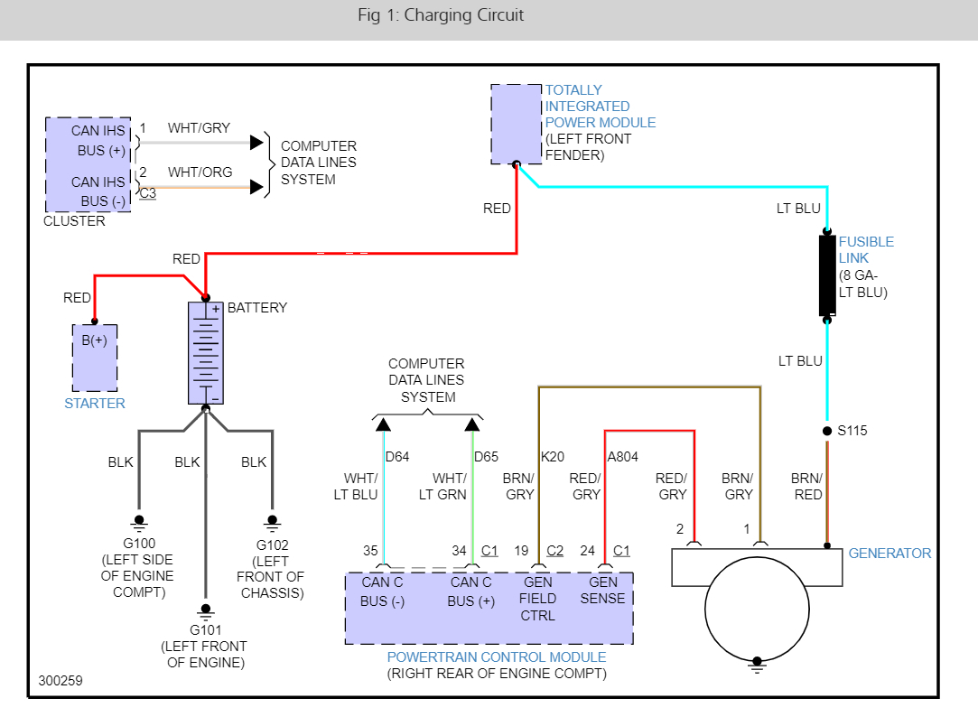
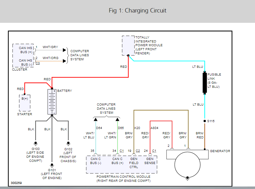
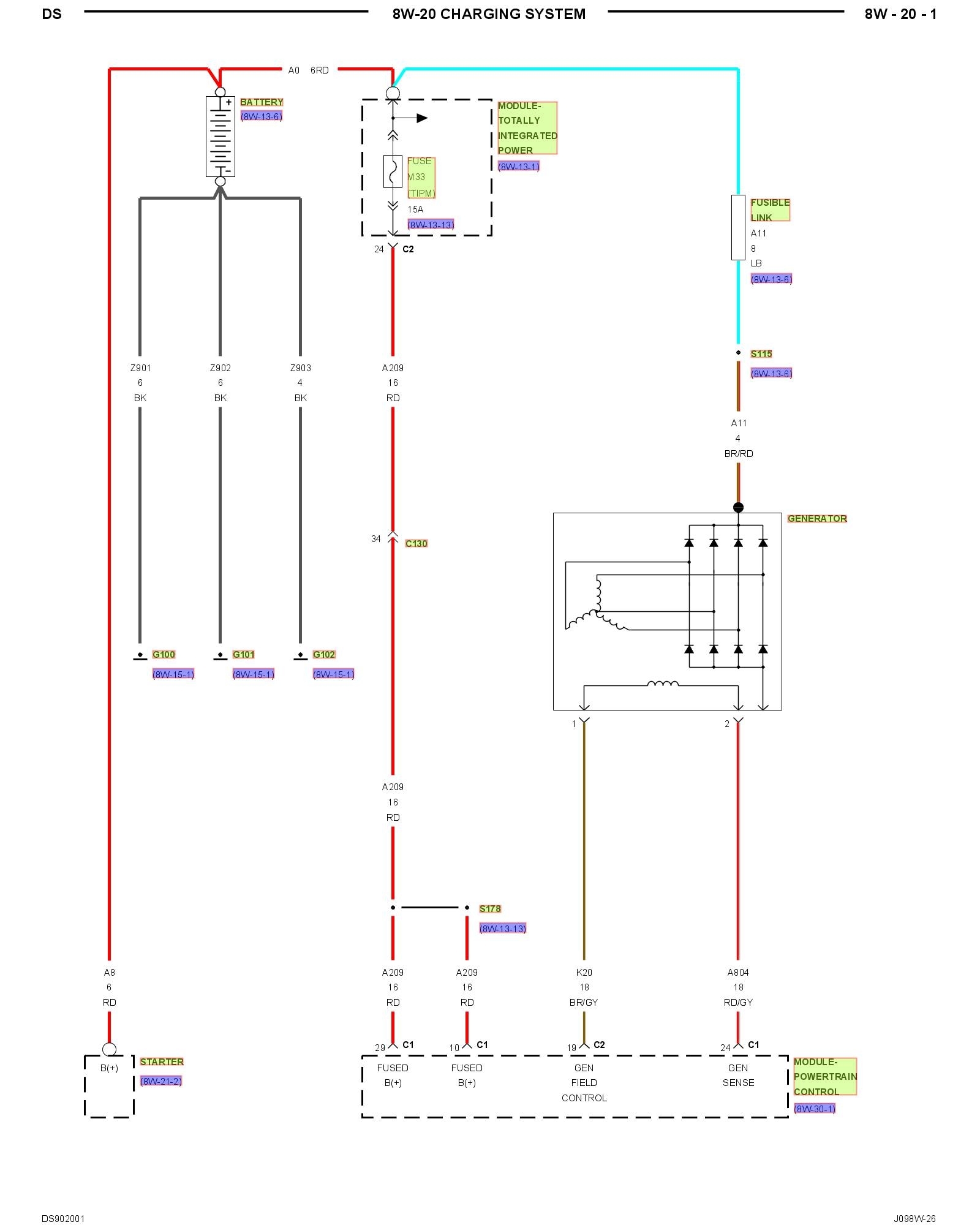
The voltage regulator is part of the power-train control module (PCM). It is not serviceable.

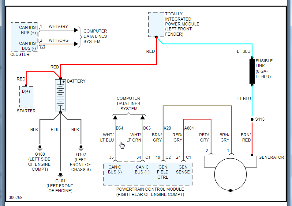
First, are you sure the alternator is good? Here is a link explaining how to test to see if there is power to the battery from the alt. Try this and let me know the results.

https://www.2carpros.com/articles/how-to-check-a-car-alternator

If there is no power, I would recommend (before replacing the PCM which can be expensive), remove the alternator and have it bench tested at a parts store. Most will do it at no charge. That way we can confirm which is truly the issue.

Here is a link that shows in general how to remove and replace an alternator. This is if you want to check it.

https://www.2carpros.com/articles/how-to-replace-an-alternator

Here are the directions specific to your car. The attached pictures correlate with the directions.

________________________________
2001 Dodge or Ram Truck RAM 1500 Truck 4WD V8-5.2L VIN Y
Generator Replacement
Vehicle Starting and Charging Charging System Alternator Service and Repair Procedures Generator Replacement
GENERATOR REPLACEMENT
REMOVAL

WARNING: DISCONNECT NEGATIVE CABLE FROM BATTERY BEFORE REMOVING BATTERY OUTPUT WIRE (B+ WIRE) FROM GENERATOR. FAILURE TO DO SO CAN RESULT IN INJURY OR DAMAGE TO ELECTRICAL SYSTEM.

1. Disconnect negative battery cable at battery.
2. Remove generator drive belt.

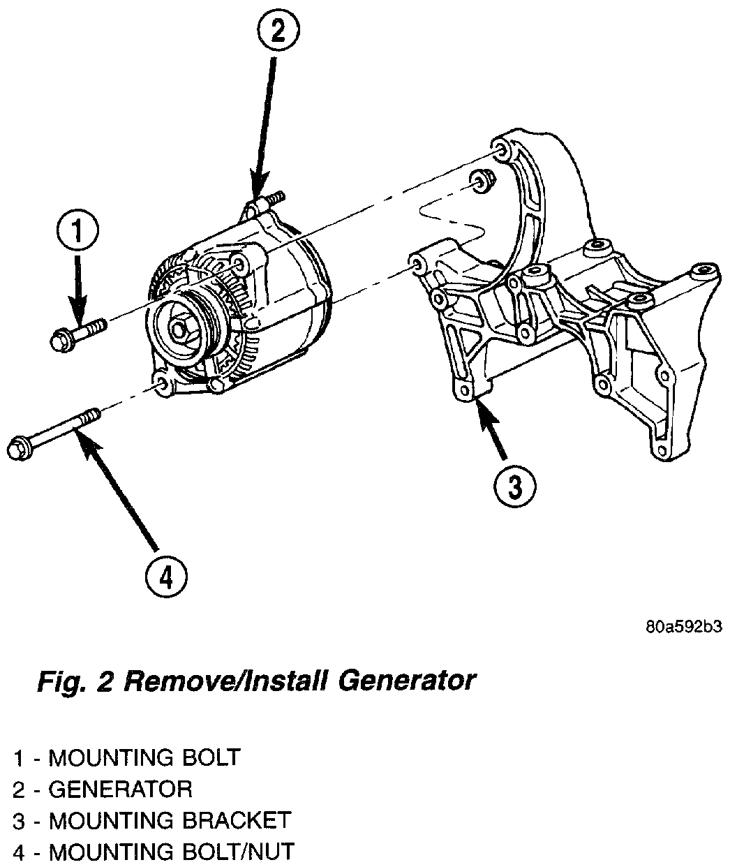
Fig.2 Remove/Install Generator
pic 1

3. In these Engines: Remove generator pivot and mounting bolts/nut (Fig. 2).
4. All Engines: Remove upper generator mounting bolt and lower mounting bolt/nut.

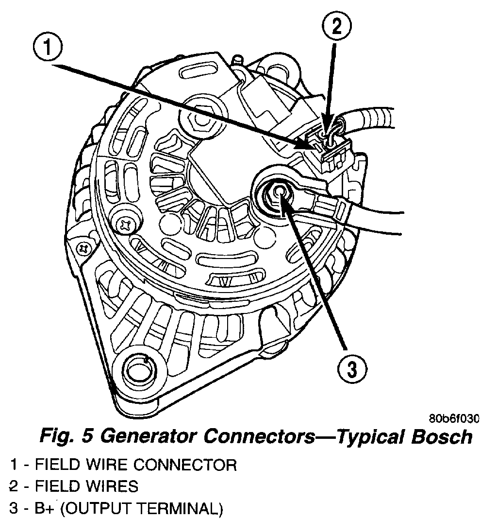
Fig.5 Generator Connectors - Typical Bosch
pic 2

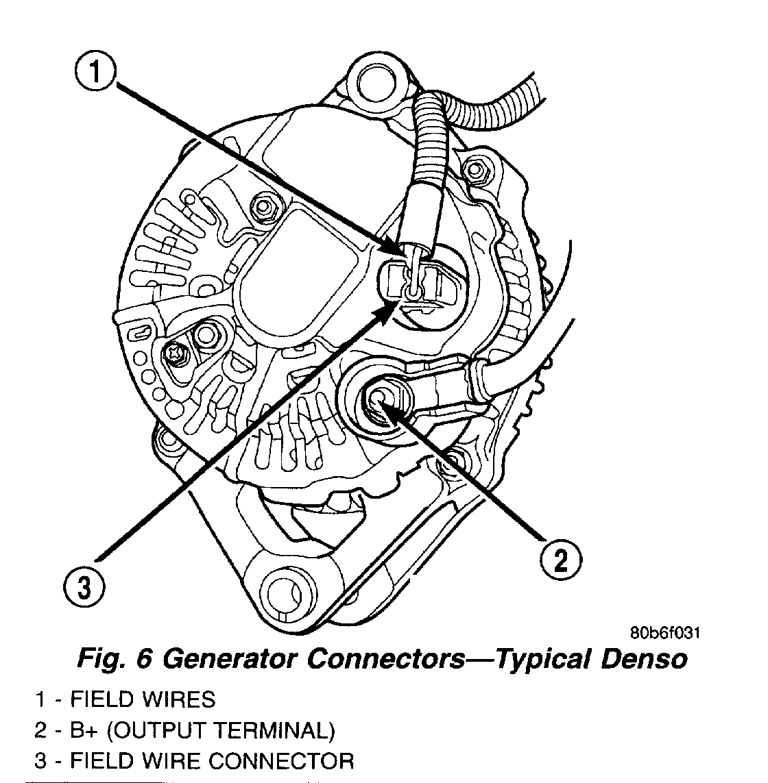
Fig.6 Generator Connectors - Typical Denso
pic 3

5. Remove B+ terminal mounting nut at rear of generator (Fig. 5) or (Fig. 6). Disconnect terminal from generator.
6. Disconnect field wire connector at rear of generator by pushing on connector tab.
7. Remove generator from vehicle.

INSTALLATION
1. Position generator to engine and snap field wire connector into rear of generator.
2. Install B+ terminal eyelet to generator stud. Tighten mounting nut to 12 Nm (108 in. lbs.) torque.
3. Install generator mounting fasteners and tighten as follows:
- Generator mounting bolt-All these powered engines-41 Nm (30 ft. lbs.) torque.
- Generator pivot bolt/nut-All these powered engines-41 Nm (30 ft. lbs.) torque.

CAUTION:
- Never force a belt over a pulley rim using a screwdriver. The synthetic fiber of the belt can be damaged.
- When installing a serpentine accessory drive belt, the belt MUST be routed correctly. The water pump will be rotating in the wrong direction if the belt is installed incorrectly, causing the engine to overheat. Refer to belt routing label in engine compartment.

4. Install generator drive belt.
5. Install negative battery cable(s) to battery(s).

____________________________

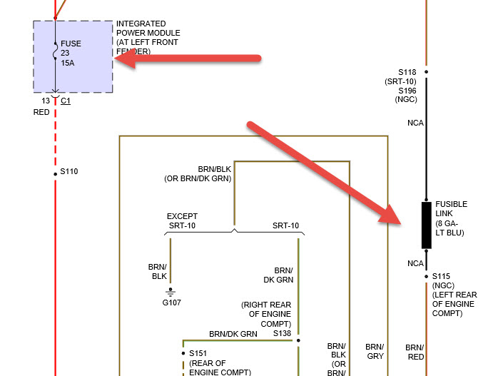
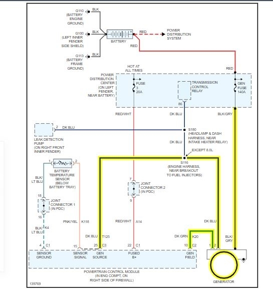
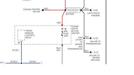
There is one other thing. There is an alternator cartridge fuse in the power distribution box. It is a 140 amp fuse. This fuse has a color-coded plastic housing and a clear plastic fuse conductor inspection cover like other cartridge fuses, but has a higher current rating and is connected and secured with screws instead of being pushed onto male spade-type terminals. The generator cartridge fuse cannot be repaired and, if faulty or damaged, it must be replaced. I doubt this is the cause, but anything is possible.

Let me know if any of this helps or if you have other questions.

Take care,
Joe
Jun 23, 2021 at 6:48 PM (Merged)
Avatar
ASEMASTER6371
  • CERTIFIED EXPERT
  • 52,796 POSTS
Good afternoon,

I attached a wiring diagram for you to view.

Make sure you have power from the battery to the big stud.

https://www.2carpros.com/articles/how-to-check-a-car-alternator

I attached a flow chart for you to follow to determine the failure.

Roy


The other 2 wires go to the ECM. The ECM turns the alternator on and off based on electrical load.

The following procedures may be used to diagnose the charging system if:
the check gauges lamp (if equipped) is illuminated with the engine running
the voltmeter (if equipped) does not register properly
an undercharged or overcharged battery condition occurs.

Remember that an undercharged battery is often caused by:
accessories being left on with the engine not running
a faulty or improperly adjusted switch that allows a lamp to stay on. Refer to Ignition-Off Draw Test in Battery for more information.

INSPECTION
The Powertrain Control Module (PCM) monitors critical input and output circuits of the charging system, making sure they are operational. A Diagnostic Trouble Code (DTC) is assigned to each input and output circuit monitored by the On-Board Diagnostic (OBD) system. Some charging system circuits are checked continuously, and some are checked only under certain conditions.

Refer to Diagnostic Trouble Codes in; Powertrain Control Module; Electronic Control Modules for more DTC information. This will include a complete list of DTC's including DTC's for the charging system.

To perform a complete test of the charging system, refer to the appropriate Powertrain Diagnostic Procedures and the DRB III scan tool. Perform the following inspections before attaching the scan tool.
1. Inspect the battery condition. Refer to Battery for procedures.
2. Inspect condition of battery cable terminals, battery posts, connections at engine block, starter solenoid and relay. They should be clean and tight. Repair as required.
3. Inspect all fuses in both the fuseblock and Power Distribution Center (PDC) for tightness in receptacles. They should be properly installed and tight. Repair or replace as required.
4. Inspect generator mounting bolts for tightness. Replace or tighten bolts if required. Refer to the Generator Removal/Installation for torque specifications.
5. Inspect generator drive belt condition and tension. Tighten or replace belt as required. Refer to Belt Tension Specifications in, Cooling System.
6. Inspect automatic belt tensioner (if equipped).
7. Inspect generator electrical connections at generator field, battery output, and ground terminal (if equipped). Also check generator ground wire connection at engine (if equipped). They should all be clean and tight. Repair as required.
Jun 23, 2021 at 6:48 PM (Merged)
Avatar
FRANKIEDONNN
  • MEMBER
  • 60 POSTS
Hi asemasters. The 140 amp fuse is good and I took it out and cleaned the area and the battery cables. Only battery voltage exists at the battery with the engine running; I keep the battery charged with a charger and it charges good, so I don't think that there is a battery problem. I don't have a drb3 scanner nor a bi-directional; only an Innova 31603 scanner and a VOM and a test light. If I can bench test the alt. myself I would, but taking it to a shop right now is not possible. I checked the white/blue and the green/white wires going into the rear of the alt.and no voltage is there nor at the PCM. I don't have the experience that you guys have and I am trying to build my confidence. If there is anything else that I can test with the tools I have let me know. Do you think it is the PCM? Thank you all who have responded, I appreciate it. Frank
Jun 23, 2021 at 6:48 PM (Merged)
Avatar
ASEMASTER6371
  • CERTIFIED EXPERT
  • 52,796 POSTS
Frank, I would remove the alternator and take it to a parts store and have them test it. They have the equipment to run it on a test bench. It is a free service.

Then you can be sure if it is good or bad.

Roy
Jun 23, 2021 at 6:48 PM (Merged)
Avatar
MERLYN LEWIS
  • MEMBER
  • 1 POST
Alternator is not charging the battery. Also, cannot connect to DLC. Dome lights and cargo light do not light up. Also, replaced alternator, still no difference. Any help would be greatly appreciated.
Jun 23, 2021 at 6:48 PM (Merged)
Avatar
STEVE W.
  • CERTIFIED EXPERT
  • 15,113 POSTS
Check that the 140 amp fuse for the alternator is good as well. Check fuse 12 (10A) for the lights and DLC failure.
Jun 23, 2021 at 6:48 PM (Merged)
Avatar
RSWALVE
  • MEMBER
  • 3 POSTS
Hi, I think this question was asked pertaining to a diesel in the past. This is about a Ram 2500 with a gas V-10 I had the Alt. rebuilt with new brushes and it seems to be working. I have about 14 volts to the distribution box on the DS fender. Voltage to the small terms on the Alt. show battery voltage on one and about .5 volts on the other. I can't seem to get a charge back to the battery though. I have heard mention of the speed sensor but the tach works... I'm lost.??????
Jun 23, 2021 at 6:49 PM (Merged)
Avatar
JDL
  • CERTIFIED EXPERT
  • 16,098 POSTS
Hi, use a digital multimeter across battery posts, everything turned off. The generic spec for a fully charged battery is around 12.6 volts. With engine running, take second reading across battery posts, the second should be higher than the first, if charging system is working.

The bat terminal at the alternator, black wire with gray tracer, should be hot even with everything turned off.

You may have to check to see if there is a trouble code for the charging system. Let us know what you find.
Jun 23, 2021 at 6:49 PM (Merged)
Avatar
RSWALVE
  • MEMBER
  • 3 POSTS
The bat terminal at the alternator, black wire with gray tracer, should be hot even with everything turned off.

I have 0 volts at the Alt.(Black / greytracer) wire.
Jun 23, 2021 at 6:49 PM (Merged)
Avatar
JDL
  • CERTIFIED EXPERT
  • 16,098 POSTS
Check the generator fuse, also check voltage to the fuse.


https://www.2carpros.com/forum/automotive_pictures/170934_dodge_generator_fuse_1.jpg

Jun 23, 2021 at 6:49 PM (Merged)
Avatar
RSWALVE
  • MEMBER
  • 3 POSTS
Yes, I was the 140 amp fuse link.

Thx so much!
Jun 23, 2021 at 6:49 PM (Merged)