Fuse 13 burn all the time

2000 CADILLAC DEVILLE
130,000 MILES
Avatar
EFFI LAHAV
  • MEMBER
  • 37 POSTS
In my Deville 2000 ,fuse #13 blow all the time . I checked that there is 12v from the DIM To one side of the fuse, I checked the license plate lights , and all o.k. , no shortage or cuts in the wires.
Where can I look that can cause the fuse to burn?
Dec 21, 2011 at 8:14 PM
Advertisement
Avatar
FIXITMR
  • CERTIFIED EXPERT
  • 9,990 POSTS
you need a wiring/fuse path diagram.
Dec 21, 2011 at 8:54 PM
Avatar
EFFI LAHAV
  • MEMBER
  • 37 POSTS
Thats what i have ,but i realy dont know, were to get from here.....
Dec 21, 2011 at 9:11 PM
Advertisement
Avatar
FIXITMR
  • CERTIFIED EXPERT
  • 9,990 POSTS
well, it looks like DIM and multi switch are on same fuse.
Dec 21, 2011 at 10:02 PM
Avatar
EFFI LAHAV
  • MEMBER
  • 37 POSTS
The DIM and multi switch are on fuse #13 ,thats blows. The DIM output (to the the fuse) is 12v which O.K. What units do i need to look for shortedg?
Dec 21, 2011 at 10:29 PM
Avatar
FIXITMR
  • CERTIFIED EXPERT
  • 9,990 POSTS
unplug both items and replace fuse. plug back in to see which is offender
Dec 21, 2011 at 10:30 PM
Avatar
EFFI LAHAV
  • MEMBER
  • 37 POSTS
Which unit is the "multi switch" ?
Dec 21, 2011 at 10:33 PM
Avatar
FIXITMR
  • CERTIFIED EXPERT
  • 9,990 POSTS
its your steering column turn stalk(and more).
Dec 21, 2011 at 11:36 PM
Avatar
EFFI LAHAV
  • MEMBER
  • 37 POSTS
Yes it is. No problem. ??
Dec 22, 2011 at 2:06 AM
Avatar
FIXITMR
  • CERTIFIED EXPERT
  • 9,990 POSTS
you lost me. diagram shows 3 possible end points for voltage from fuse. 1 of them must be causing short. have you found which 1?
Dec 22, 2011 at 4:00 AM
Avatar
EFFI LAHAV
  • MEMBER
  • 37 POSTS
What I understand (and it’s not much, since I know very little about electrical). I can see:
1. DIM that provide the 12v to the fuse (so it cannot be shortage)
2. The Turn signal which works o.k. (Unless it can be short but I don’t know how to check)
3. The 2 license lights that also works o.k. (Unless it can be short but I don’t know how to check)


It’s possible that I think its all wrong, Can you please direct me how to check the 3 of them for short? (I defiantly can check for short)
Dec 22, 2011 at 5:20 AM
Avatar
FACTORYJACK
  • CERTIFIED EXPERT
  • 4,159 POSTS
Look at the possibles, and make it as basic as possible. Could the DIM be shorted?, possible but not probable. Could the multifunction switch itself be shorted?, possible but not probable. Could the license plate applique mounting bolts be anchoring the harness to the deck lid creating a direct short to ground, probable and possible. Remove the trunk lining, loosen the nuts for the applique, and inspect the wiring. Also check the pivot area, where the harness runs from the rear deck lid to the vehicle. It could be pinched in the hinge area. Looking at the schematic, if the DIMR fuse is #13, you can isolate all three circuit at the connector under the fuse block. It shows you in the upper RH corner of the schematic, that connector C! is a 50 or 60(hard to read) pin gray connector body. From there, if you can find the two terminals(B4 single yellow, and A7 double yellow), you can do some diagnosing. Check the single wire terminal for a short to ground, and based on the result, check the double side. Now if you find a short on the double wire terminal, cut one away, and see which of the two is shorted to ground. If the fuse is continuously blowing, it should not be that hard to find. If it is intermittent in nature, you could cut all three wires, install inline fuse holders in each, and equip the fuse holders with either 7.5 amp, or even 5 amp fuses. When you have a problem, the open fuse will indicate which circuit to devote your effort to.
Dec 22, 2011 at 5:53 AM
Avatar
EFFI LAHAV
  • MEMBER
  • 37 POSTS
factoryjack , Thank you for the detail answer. I understand your answer but I will follow your direction on the weekend and I will let you know.
Have a Merry Christmas!
Effi
Dec 22, 2011 at 9:51 PM
Avatar
EFFI LAHAV
  • MEMBER
  • 37 POSTS
factoryjack
Factoryjack
I am following your direction, but I cannot find connector C . You say it’s a 50 or 60 pin gray connector body. Can you please direct me where its located. (I don’t see a gray,50 pin connector anywhere….)
Dec 24, 2011 at 5:29 PM
Avatar
EFFI LAHAV
  • MEMBER
  • 37 POSTS
I am following "factoryjack" direction, but I cannot find connector C (50 or 60 pin gray connector). Can someone please direct me were can i find connector C ?
Dec 25, 2011 at 2:05 PM
Avatar
FACTORYJACK
  • CERTIFIED EXPERT
  • 4,159 POSTS
It is under the rear fuse block. A 50/60 pin gray connector. Each connector will be a different color, it is the gray one you are looking for. C1
Dec 25, 2011 at 6:29 PM
Avatar
EFFI LAHAV
  • MEMBER
  • 37 POSTS
There is nothing under the rear fuse block onlt the base frame that the fuse block is attached with scres. (My car is 2000 deville).
Dec 25, 2011 at 6:56 PM
Avatar
FACTORYJACK
  • CERTIFIED EXPERT
  • 4,159 POSTS
Have you separated the base from the block itself?
Dec 25, 2011 at 8:13 PM
Avatar
EFFI LAHAV
  • MEMBER
  • 37 POSTS
There is nothing under the rear fuse block, onlt the base frame that the fuse block is attached with scres. (My car is 2000 deville).
Thast the pic for the rear fuse block under the back site.
Dec 25, 2011 at 8:15 PM
Avatar
EFFI LAHAV
  • MEMBER
  • 37 POSTS
the plastic base? into 2 peaces?
Dec 25, 2011 at 8:16 PM
Avatar
FACTORYJACK
  • CERTIFIED EXPERT
  • 4,159 POSTS
Yes, there are four clips that secure it to the base. Once separated from the base, there should be at least 5 connectors. 3 of which are 68 pin, and 2 are two pin at least.
Dec 25, 2011 at 8:19 PM
Avatar
EFFI LAHAV
  • MEMBER
  • 37 POSTS
There is a gray connector
on this one i need to find the (B4 single yellow, and A7 double yellow) and go from there?
this is the pic. the gray connector is on the right and B4 the single yellow is on to left of the pic?
Dec 25, 2011 at 8:49 PM
Avatar
EFFI LAHAV
  • MEMBER
  • 37 POSTS
Sorry, i inted to put this pics.
(B4 single yellow, and A7 double yellow) and go from there?

Dec 26, 2011 at 1:45 PM
Avatar
FACTORYJACK
  • CERTIFIED EXPERT
  • 4,159 POSTS
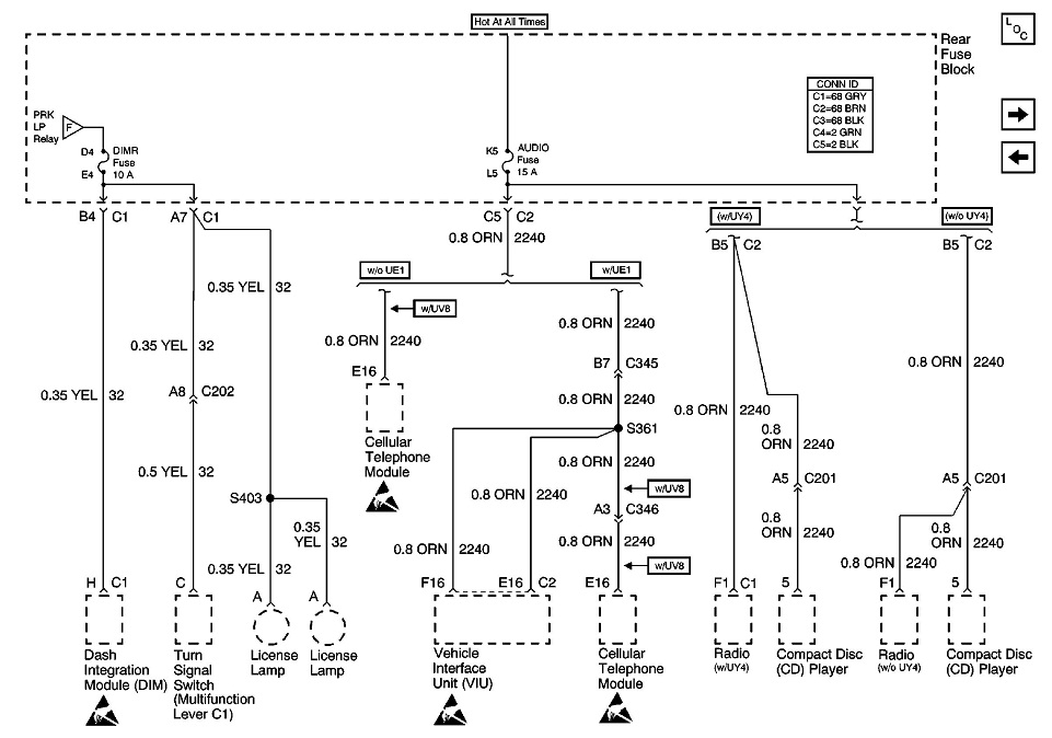
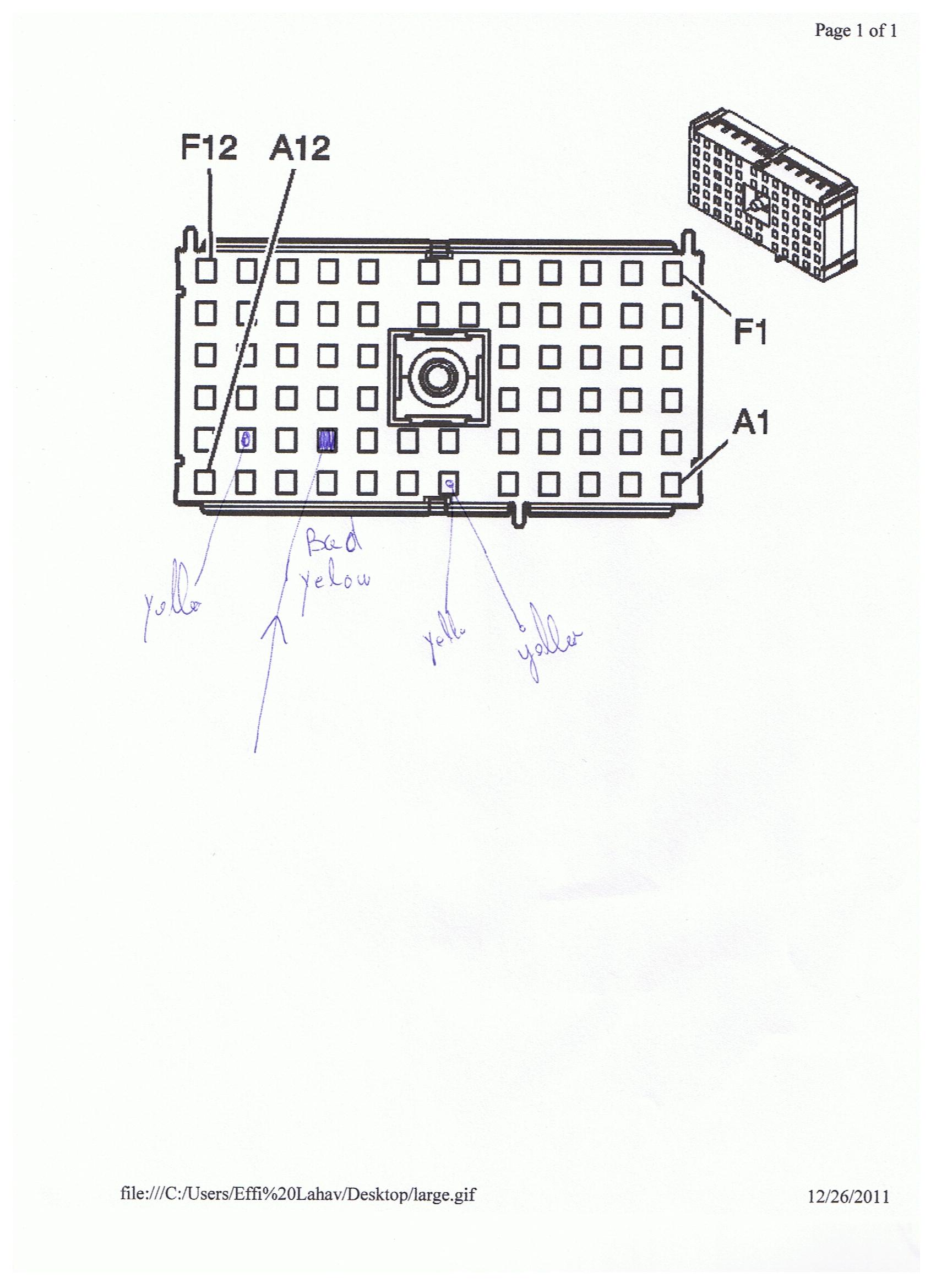
See if this helps, it is a connector end view of C1 connector. The picture is a bit hard to identify with any detail, but you are in the right place.


f


Connector Part Information


15303512


68 Way F Metri-Pack 280 Series (GRY)


Pin


Wire Color


Circuit No.


Function


A1


ORN


1140


Battery Positive Voltage (B+)


A2


Not Used


A3


BRN/WHT


309


Park Lamp Feed - Right


A4


ORN


2247


Fuse Output - Sunshade (Export)


A5


ORN


3240


Fuse Output - Battery (w/UY4, UE7/UE9)


A6


Not Used


A7


YEL


32


Fuse Output - Lamps


A8


Not Used


A9


ORN


1740


Battery Positive Voltage


A10


BRN


141


Ignition Positive Voltage


A11


ORN


300


Ignition Positive Voltage


A12-B1


Not Used


B2


YEL


1139


Ignition Positive Voltage


B3


BRN/WHT


309


Park Lamp Feed - Right (Domestic)


B4


YEL


32


Fuse Output - IP Lamps


B5


PNK/BLK


1615


Park Relay Output - Coil


B6


LT GRN


275


Park Relay Output - Switch Side


B7


DK GRN


646


Reverse Relay Coil Control (Export)


B8


LT GRN


24


Back-up Lamp Feed


B9-C4


Not Used


C5


ORN


1640


Battery Positive Voltage (B+)


C8


LT GRN


24


Back-Up Lamp Feed


C9


ORN


540


Battery Positive Voltage (B+)


C10


Not Used


C11


BRN


41


Ignition Positive Voltage (DTS)


C12


BRN


241


Ignition Positive Voltage


D1


Not Used


D2


BLK


750


Ground


D3


Not Used


D4


DK GRN


1483


Control Power Output


D5


Not Used


D8


LT GRN


24


Back Up Lamp Feed (w/JL4 or w/T90)


D9


PNK


70


Ignition Positive Voltage


D10


DK GRN


1399


Cigar Relay Coil Control


D11


BRN


41


Ignition Positive Voltage (w/o?B9Q)


D12


Not Used


E1


ORN


2840


Battery Positive Voltage (B+) (w/o?B9Q)


E2- E3


Not Used


E4


PPL


709


Park Lamp Feed - Left (Domestic)


E5


Not Used


E6


PPL


709


Park Lamp Feed - Left


E7, E8


Not Used


E9


ORN


540


Battery Positive Voltage (B+)


E10


ORN


540


Battery Positive Voltage (B+)


E11


BRN


41


Ignition Positive Voltage


E12


ORN


3740


Ignition Positive Voltage


F1


GRN DK /WHT


465


Fuel Pump Relay Feed - Coil


F2


GRY


120


Fuel Pump Motor Feed


F3


WHT


1080


Park Lamp Relay Control


F4


Not Used


F5


ORN


840


Battery Positive Voltage (B+) (w/o?B9Q)


F6


Not Used


F7


BRN


741


Ignition Positive Voltage (w/UV2)


F8


BRN


741


Ignition Positive Voltage (w/UV2)


F9-F10


Not Used


F11


BRN


41


Ignition Positive Voltage


F12


ORN


3740


Battery Positive Voltage

Dec 26, 2011 at 4:28 PM
Avatar
EFFI LAHAV
  • MEMBER
  • 37 POSTS
Thats the connector. The schem details did not printed right. Can you please copy to "word" file and upload as "word"?
thanks
Dec 26, 2011 at 6:23 PM
Avatar
FACTORYJACK
  • CERTIFIED EXPERT
  • 4,159 POSTS
If you were talking to I computer savvy person, I would have no problem doing that. What you see, is what you get. I see that all the information is spread out, and difficult to interpret. The format is this, the alpha-numeric number is connector terminal #(e.g. A1), next is wire color, after that is circuit #, and lastly a description of circuit(e.g. ignition positive voltage. If you created a grid with four columns, you would lay the information out in that order. Anything with a dash(-), is a vacant cavity.
Dec 26, 2011 at 6:51 PM
Avatar
EFFI LAHAV
  • MEMBER
  • 37 POSTS
I am arranging this now. It will take long ......long long .......time .... But it will be done
Dec 26, 2011 at 7:25 PM
Avatar
FACTORYJACK
  • CERTIFIED EXPERT
  • 4,159 POSTS
I don't understand why it would take so long, look at the connector body, and find the two terminals that you are after. Process of elimination should direct you to the correct ones. There are only three yellow wires in that entire C1 connector.
Dec 26, 2011 at 9:30 PM
Avatar
EFFI LAHAV
  • MEMBER
  • 37 POSTS
Sorry but I am not so families with electrical...
I found the yellow bad bad wire. (I marked in the attachment) Now , how do I identify circle (and eliminate/fix it ?
Thanks
Dec 26, 2011 at 10:37 PM
Avatar
FACTORYJACK
  • CERTIFIED EXPERT
  • 4,159 POSTS
I do believe you have them numbered in reverse, but that is no problem. Your first row is the A row, and shows one yellow wire in A7. The next row up is B row, you have yellow wires in B2, and B4. Disregard B2, and B4 is the one you labeled bad. What defines bad, shorted to ground, loose terminal?, explain 'bad'. Judging from the schematic, that wire runs to the front of the passenger compartment, to the dash integration module. If it is shorted to ground, you will need to locate that module, disconnect it, and recheck the wire for a short to ground. If it is still grounded, you have a short somewhere in that circuit.
Dec 26, 2011 at 11:19 PM
Avatar
EFFI LAHAV
  • MEMBER
  • 37 POSTS
Yes i installed a fuse only on the bad yellow wire and its blow, The license plate light and the turn signal light are fine only the DIM not working . I will try tomorrow and see if it’s a ground short or other short and follow. At lease i know specifics were to look.
Dec 26, 2011 at 11:57 PM
Avatar
EFFI LAHAV
  • MEMBER
  • 37 POSTS
I did some tests regarding the 3 points for the yellow wire (B2,B4,A7) to find where the short is ,and what the next step is.
This are the results with the car run and not run and with the DIM connected and NOT connected.
Can someone help me with the next step?
Thanks
Please Look At the attachment:

DIM CONECTED
B2 B4 A7

CAR OFF Short Short Short
CAR ON 12V(+ ) N-Short 12V(+)


DIM DISCONECTED
B2 B4 A7

CAR OFF Short Short Short
CAR ON 12V(+) short Short

Short = Short To Ground
N-Short = No Short To Ground
Dec 27, 2011 at 10:12 PM
Avatar
EFFI LAHAV
  • MEMBER
  • 37 POSTS
I did some tests regarding the 3 points for the yellow wire (B2,B4,A7) to find where the short is ,and what the next step is.
This are the results with the car run and not run and with the DIM connected and NOT connected.
Can someone help me with the next step?
Thanks

DIM CONECTED
B2 B4 A7

CAR OFF Short Short Short
CAR ON 12V(+) N-Short 12V(+)


DIM DIM DISCONECTED
B2 B4 A7

CAR OFF Short Short Short
CAR ON 12V(+) Short Short

Short = Short To Ground
N-Short = No Short To Ground
Dec 27, 2011 at 10:39 PM
Avatar
FACTORYJACK
  • CERTIFIED EXPERT
  • 4,159 POSTS
Now I am confused. Yesterday you said you installed a fuse holder in the circuit and determined it was on terminal B4 that the short to ground was. If this was the case, you should have simply disconnected the DIM, measured that circuit for continuity to ground, and started looking for the short along the wires routing path. You've got blown off course. Checks for short to ground should not be performed with key on, you will get incorrect results. With both ends of a wire disconnected from a component, if you still show continuity to ground, the wire is shorted.
Dec 27, 2011 at 10:49 PM
Avatar
EFFI LAHAV
  • MEMBER
  • 37 POSTS
I follow your direction and I found the 2 yellow wires melted together. It was a big horrreeeee but not for long. I replaced the cables, connect and found that I still have one of the yellow short to the ground. T
he yellow wire is goes inside the frame with the braid cable . Where do I go now????
Dec 28, 2011 at 2:11 AM
Avatar
FACTORYJACK
  • CERTIFIED EXPERT
  • 4,159 POSTS
Inside the frame with the braid cable, I am not certain what your talking about. If it is heading toward the rear of the vehicle, it is going to the lic plate lights. Running toward the front it is feeding the turn signal switch(multifunction). There is a connector in one branch of the circuit that has a connector in it(C202). If you can find that connector, and disconnect it, check your wire for a short. If you detect no short from the wire to C202, check it from C202. This is breaking the circuit down. If it is going to the rear, follow it past the hinge, and to the rear lic plate lights. I would suspect you will either find it grounded at the license plate pocket mounting, or chaffed at the park brake mechanism.
Dec 28, 2011 at 5:20 AM
Avatar
EFFI LAHAV
  • MEMBER
  • 37 POSTS
I will work on that tonight ,but I don’t understand how it can grounded at the “park brake mechanism” ?
Dec 28, 2011 at 6:16 PM
Avatar
FACTORYJACK
  • CERTIFIED EXPERT
  • 4,159 POSTS
Chewed through, pinched, and shorted to the chassis.
Dec 28, 2011 at 6:27 PM
Avatar
EFFI LAHAV
  • MEMBER
  • 37 POSTS
I found (C202) (driver side under the steering column.) I disconnect it and there are 3 yellow wires at the plug. 2 of them are grounded (and short to the yellow wire that I disconnect from the DIM (and run to the fuse box) ??
Dec 29, 2011 at 12:57 AM
Avatar
FACTORYJACK
  • CERTIFIED EXPERT
  • 4,159 POSTS
At C202, there is only 1 yellow wire to be concerned with. Pin A8 is circuit 32, from the fuse block to the turn signal switch. If you have C202 disconnected, and C1 at the fuse block, put an ohmmeter lead in the terminal that has 2 yellow wires(at C1), and you should be able to locate A8 with the other meter lead. Once you find the wire between the fuse block and C202, leave one meter lead in either end, and touch a good ground. If you have low resistance to ground, it is shorted somewhere between the fuse block and the harness side of C202, this will also include other wire that runs to the license plate lamps. You would have to separate the two yellow wires from the one terminal, because if you show a short to ground, it still could be in the wire to the license plate lamps. If you had three separate wires at the fuse block, you could check each the same way. With the license plate bulbs installed in the sockets, you will have continuity to ground through the bulb filaments, so keep that in mind. I'll tell you what I would do. Working from the fuse block, with C202 and the DIM disconnected, and the license plate bulbs removed, or disconnected if there are connectors to the sockets, Take an ohmmeter with one lead to ground(battery negative post is real close, and the best ground), probe each of the yellow wires at C1 with the other lead. Whichever lead you have low resistance to ground on, is your shorted wire. This is all under the assumption that the fuse immediately opens any time you replace it. If it is intermittent, we have been spinning wheels. What you can be faced with if you have connections made, or a key on, is a misleading continuity to ground through completed circuits, and you will chase your tail. Checking for ground should be open-ended, wires only, very basic. In my opinion, if you are continuously blowing fuses, the short to ground should be easy to find.
Dec 29, 2011 at 3:21 AM
Avatar
EFFI LAHAV
  • MEMBER
  • 37 POSTS
Well, it took me few days but I am getting closer. Follow …….directions I was able to locate the yellow wire that is short to ground , It’s the yellow wire that connect to the DIM on the smallest plug (there are 3 plugs in the DIC and it’s the only yellow that connect to the small plug.
I cut the wire and try to do bypass directly to C1 at the fuse block (But I don’t know if that the right place to do it ) and I don’t want to take risks so I decide to wait that someone know how to bypass that short wire.?
I attaches photo of the DIM (passenger side above the legs) and the plugs on it.The yellow wire is connect ON the left small plug in the pics.
Dec 31, 2011 at 10:02 PM