Check the actuator and motor movement.
ACTUATOR
1. Using ohmmeter, measure resistance between terminals No. 2 and 3. Resistance should be .3-100 ohms. See Fig. 2 .
2. Using ohmmeter, measure resistance between terminals No. 2 or 3 and chassis ground. Resistance should be greater than 500 k/ohms. If resistance values are not as specified, replace actuator assembly.
3. Check actuator limit switch continuity. Connect positive lead from battery to terminal No. 2 and negative lead to terminal No. 3. Connect positive lead from ohmmeter to terminal No. 5 and negative lead to terminal No. 4. Ensure continuity exists between terminals No. 4 and 5.
4. Connect positive lead from battery to terminal No. 3 and negative lead to terminal No. 2. Connect positive lead from ohmmeter to terminal No. 6 and negative lead to terminal No. 4. Ensure continuity exists between terminals No. 4 and 6. If continuity is not as specified, replace actuator assembly.
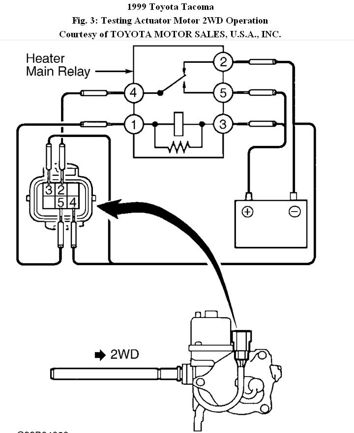
ACTUATOR MOTOR OPERATION
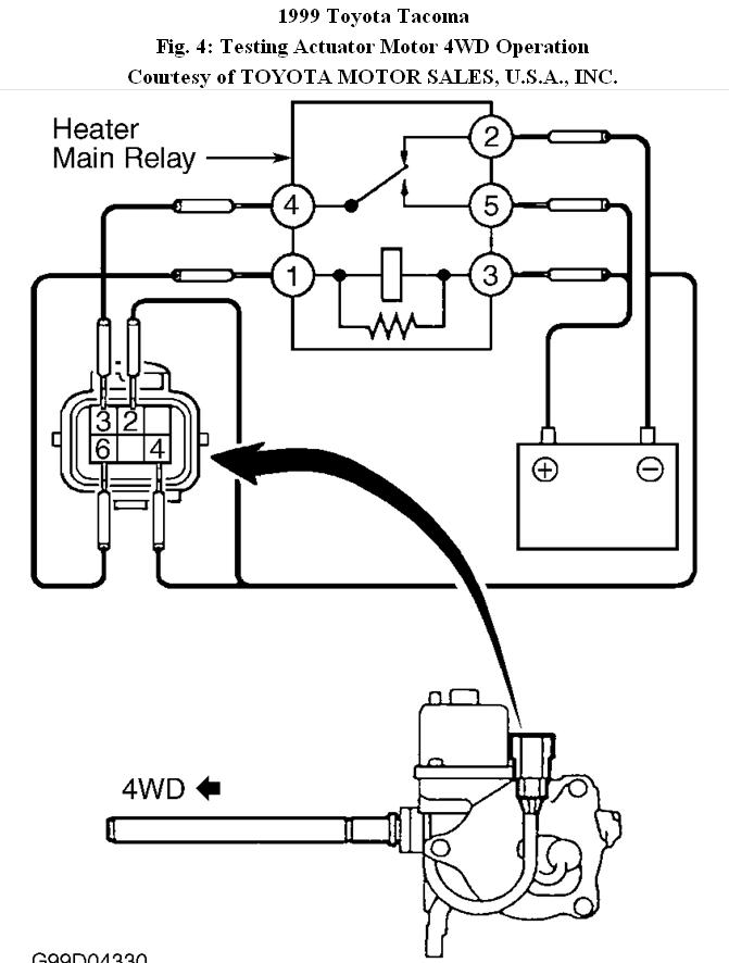
Connect heater main relay between actuator connector and battery. See
Fig. 3 . Actuator shaft fork should move to 2WD position. Connect heater main relay between actuator connector and battery. See Fig. 4 . Actuator shaft fork should move to 4WD position. If actuator does not operate as described, replace actuator.
© 2008 Mitchell Repair Information Co., LLC.
Images (Click to enlarge)
Dec 12, 2010 at 4:22 PM