Here are the diagnostic procedures if it is of any help.
DTC P1753/FLASH CODE 1: LOCK-UP CONTROL SOLENOID "A"
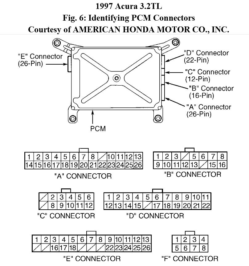
1. Turn ignition off. Disconnect PCM harness connectors "A" (26-pin) and "E" (26-pin). See Fig. 6 . Turn ignition on. Check voltage between PCM harness connector "A" terminal No. 26 (Brown/Black wire) and harness connector "E" terminal No. 13 (Yellow wire). If voltage is present, go to next step. If voltage is not present, go to step 3 .
2. Repair short to power in circuit between PCM harness connector "E" terminal No. 13 (Yellow wire) and lock-up control solenoid valve "A".
3. Turn ignition off. Check resistance between PCM harness connector "A" terminal No. 26 (Brown/Black wire) and harness connector "E" terminal No. 13 (Yellow wire). If resistance is not 12-25 ohms, go to next step. If resistance is 12-25 ohms, check for loose PCM connectors. Repair as necessary. If connectors are okay, substitute with a known-good solenoid valve assembly or PCM and recheck system. If symptom or problem goes away, replace faulty component.
4. Disconnect lock-up control solenoid valve harness connector. Check continuity between PCM harness connector "A" terminal No. 26 (Brown/Black wire) and harness connector "E" terminal No. 13 (Yellow wire). See Fig. 6 . If continuity does not exist, go to next step. If continuity exists, repair short to ground in circuit between PCM harness connector terminal No. 13 (Yellow wire) and lock-up control solenoid valve
"A".
5. Check resistance between body ground and lock-up control solenoid connector
terminal No. 2 (Yellow wire). If resistance is not 12-25 ohms, replace lock-up control solenoid valve assembly. If resistance is 12-25 ohms, check for open in circuit between PCM harness connector "E" terminal No. 13 and lock-up control solenoid valve "A".
Nov 2, 2012 at 3:18 PM