Hello
Thanks for the donation.
Replacement procedures are below for your ignition switch. These procedures are for vehicles equipped with air bag.
CAUTION: Before performing this procedure, disable the air bag system (refer ). Failure to do so could result in accidental air bag deployment and possible injury.
REMOVAL:
Disconnect the negative battery cable and disable the air bag system.
If equipped, remove the tilt lever.
Remove the upper and lower steering column covers with a suitable Torx® driver.
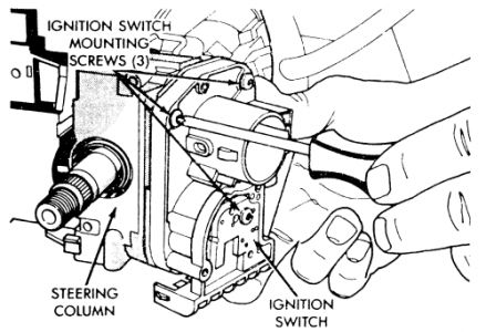
Using Snap-On® tamper-proof bit TTXR20BO or equivalent, remove the ignition switch screws.
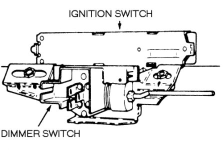
Pull the ignition switch away from the column.
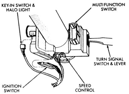
Release the 2 connector locks on the 7-terminal wiring connector and remove the connector from the ignition switch.
Release the connector lock on the key-in-switch and halo light 4-terminal connector and remove the connector from the ignition switch.
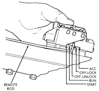
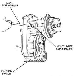
Insert the key into the ignition lock and ensure it is in the LOCK position.
Using a small screwdriver, depress the key cylinder retaining pin so it is flush with the key cylinder surface.
Turn the ignition key to the OFF position and the lock will release from its seated position.
Turn the key to the LOCK position and remove the key.
Remove the ignition lock.
INSTALLATION:
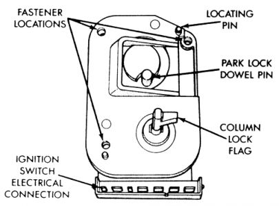
Install the electrical connectors to the switch. Ensure the switch locking tabs are fully seated in the wiring connectors.
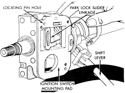
Mount the ignition switch to the column. The dowel pin on the ignition switch assembly must engage with the column park-lock slider linkage. Ensure the ignition switch is in the lock position (flag is parallel with the ignition switch terminals).
Apply a dab of grease to the flag and pin. Position the park-lock link and slider to mid-travel. Position the ignition lock against the lock housing face. Ensure the pin is inserted into the park-lock link contour slot and tighten the retaining screw.
With the ignition lock and switch in the LOCK position, insert the lock into the switch assembly until it bottoms.
Assemble the column covers.
If equipped, install the tilt wheel lever.
Connect the negative battery cable.
From the right side of the vehicle (in case of accidental deployment), turn the ignition switch to the ON position.
Check for proper air bag warning light operation.
Thanks for using 2CarPros.com!
Jan 25, 2009 at 4:16 PM