engine miss

1994 OLDSMOBILE DELTA 88
88,000 MILES • 6 CYL • FWD • AUTOMATIC
Avatar
TOBYJAY
  • MEMBER
  • 22 POSTS
I have one cylinder on a V6 1994 Oldsmobile 88 in which any fuel injector will not fire. I have verified spark and whichever injector I put in that cylinder does not fire.
I get a 12v reading at the injector harness at every injector. Is it reasonable for me to assume that the problem is with my engine computer not providing the appropriate pulse to that particular cylinder?
Mar 6, 2011 at 4:13 PM
Advertisement
Avatar
SATURNTECH9
  • CERTIFIED EXPERT
  • 30,869 POSTS
So one cylinder the injector won't pulse?If so which number cylinder?So you have power to that injector?All the other injector's pulse and work?Let me know.
Mar 6, 2011 at 4:28 PM
Avatar
SATURNTECH9
  • CERTIFIED EXPERT
  • 30,869 POSTS
Do you have a test and multimeter to do some testing?
Mar 6, 2011 at 4:29 PM
Advertisement
Avatar
SATURNTECH9
  • CERTIFIED EXPERT
  • 30,869 POSTS
Test light i mean.
Mar 6, 2011 at 4:29 PM
Avatar
TOBYJAY
  • MEMBER
  • 22 POSTS
saturntech9 - I have a multimeter. The cylinder in question is the front right cylinder. There is voltage going to that injector.
All the other injectors pulse. A lasor temperature gun shows low temp at the manifold of only this cylinder. Whichever injector I switch with this cylinder does not activate. I can hear the other injectors bt touching a long screwdriver at the base of each and placing against my ear. The front right cylinder has no injector sound. tobyjay
Mar 6, 2011 at 5:04 PM
Avatar
RASMATAZ
  • CERTIFIED EXPERT
  • 75,992 POSTS
Test that cylinder ground driver circuit back to the computer
Mar 6, 2011 at 5:09 PM
Avatar
TOBYJAY
  • MEMBER
  • 22 POSTS
Would a proper test be to connect my voltmeter between the grounding side of the injector plug and the positive side of my battery while cranking the engine with the ignition disabled?
If the trigger pulse is working I should see a jumping voltmeter.
Is this the correct method ?
Mar 6, 2011 at 5:16 PM
Avatar
TOBYJAY
  • MEMBER
  • 22 POSTS
It appears my digital voltmeter does not respond fast enough to see the fluctuations in voltage from the trigger signal. With the ignition disabled, each injector, including the suspect cylinder,
shows the same steady voltage from battery plus to the injector ground terminal when cranking the engine. I'm now looking for an analog voltmeter to see if that will help me see the trigger signal. Razmataz or Saturntech9 - Am I going in the right direction?
Mar 6, 2011 at 6:22 PM
Avatar
TOBYJAY
  • MEMBER
  • 22 POSTS
For what it's worth here's what I saw when I used an older voltmeter
with a needle. With motor running - rapid voltage fluctuations (trigger signal) on every cylinder except the suspect cylinder.
That cylinder showed no movement on the meter. At this point I see no other culprit but the ECM. If anyone out there has another suspicion, I would like to hear from you. Thanks. tobyjay
Mar 6, 2011 at 6:50 PM
Avatar
RASMATAZ
  • CERTIFIED EXPERT
  • 75,992 POSTS
Disconnect the computer and check the wire for open -if okay think! computer-
Mar 6, 2011 at 8:35 PM
Avatar
SATURNTECH9
  • CERTIFIED EXPERT
  • 30,869 POSTS
The best way to test it is to get a bulb test light ground the lead end and and use the tip to see if you have power to one side of the none working injector key in the run position.Then hook the lead end to the power side of the battery and use the tip side to see if you have a ground pulse to the other side of the injector while cranking it or the engine running.After seeing what side of the circuit is missing then we can go from there.If your getting power we would have to trace the wire down.If we have no ground pulse then we have a open in the circuit loose terminal tightness or a bad ecm.But we have to rule out the other two before replacing a ecm.Let me know what you find.Also what cylinder is the none working injector on?
Mar 6, 2011 at 8:49 PM
Avatar
TOBYJAY
  • MEMBER
  • 22 POSTS
To razmataz and saturntech9 - I did what each of you suggested and located each of the injector wires through color code where they appeared on a plug at the ECM. A continuity check from the injector plug showed each wire to be good. Guess the only thing left is to replace the ECM. If you guys agree, let me know - and thanks for all the suggestions - you've both been a big help!
Mar 6, 2011 at 11:14 PM
Avatar
SATURNTECH9
  • CERTIFIED EXPERT
  • 30,869 POSTS
The question's i have for you before you go changing the ecm is did you check to see if you were getting battery voltage to the other wire to the injector that doesn't go to the ecm with the key in the run position?Also did you check for a flashing ground with a bulb test light on the wire going back to the ecm when cranking the car or it running?I just want to make sure all the base's are covered.
Mar 7, 2011 at 2:34 AM
Avatar
TOBYJAY
  • MEMBER
  • 22 POSTS
To saturntech9 - both wires on the injector go back to the ECM.
I am getting battery voltage measured across the two pins of the injector with the key in the run position. I checked for a flashing ground with an analog voltmeter while cranking the car. The voltmeter had no movement at all at the suspect cylinder, but did jump rapidly back and forth when the same check was done on other injectors. What do you think?
Mar 7, 2011 at 1:20 PM
Avatar
SATURNTECH9
  • CERTIFIED EXPERT
  • 30,869 POSTS
I have never tried to check for injector pulse with a meter i always use a noid light or better yet a test light so you can check the power and the ground pulse seperate.Only one wire at each connector goes back to the ecm that"s the ground control.The other wire goes to the fuse box.I posted a wire diagram showing each wire to the injector's let me know if the wire color's match up.Also that inop injector shouldn't read 12 volt's across it.As you can see in the wire diagram the ground control side going back to the ecm that ground is normally open.Meaning unless the ecm is sending out a pulse ground signal there shouldn't be a constant ground to that wire.Otherwise that injector would just stay open.Try this check that wire to the inop injector that doesn't have power which would be the none pink from what i see in the diagram.Put your meter on low scale ohm's ground the black lead.Now touch the red lead to that non power wire to the inop injector.Does the meter show a ohm's reading?If so unplug the connectors to the ecm and check it again.Is the ground gone now?If you still have a ground to that injector wire then you have a pinched wire shorted to ground some where.Make sure when you unplug the ecm the ignition key is off.Let me know what you find.
Mar 7, 2011 at 5:42 PM
Avatar
TOBYJAY
  • MEMBER
  • 22 POSTS
Is it possible that on different cars the pink wire you show going to the fuse might be getting the plus side voltage through a connection at the ECM ? I ask this because I definitely found continuity with the key off from the pink wire at the injector and what I believe to be the same pink wire at a plug on the ECM.
I understand the wiring diagram you sent, however, I do get 12V. across the two injector terminals with the key on - and this is for all the injectors. As far as pulse coming from the ECM grounding and ungrounding one conductor - my voltmeter showed pulsations between battery plus and injector black/white with the engine running. These pulsations showed only on the working injectors and not the silent one. What makes this even more puzzling is that this morning I started the car and knew immediately that all 6 cylinders were firing. It has been intermittant before but it's been quite a while. Maybe it's nothing more than a less than solid connection at one of the ECM plugs? I have to take a 1400 mile trip with this vehicle in three weeks so I really want to solve this.
Mar 7, 2011 at 7:47 PM
Avatar
SATURNTECH9
  • CERTIFIED EXPERT
  • 30,869 POSTS
The power to be sent from the ecm to the injector's i really don't see that happening ecm's control ground usually if they ran too much power thru them like for those injector's then the ecm would overheat and burn up pretty fast i would think.Try pulling that fuse in the wire diagram i posted see if the power to the injector's goes away?That would tell you right there.It sound's like a bad connection issue at the ecm if everything is firing now.I would let it idle and move the wire's around light tugging etc and see if the engine start's missing.Let me know what you find.
Mar 7, 2011 at 9:05 PM
Avatar
TOBYJAY
  • MEMBER
  • 22 POSTS
To Saturntech9 : Took me a few days to get a new ECM and try it out. Moved the prom from the old ECM to the new one.
The news is that it appears to have solved my problem. All injectors
are firing and the car runs normally with full power again. Removed a cable from the battery while making the change. Now I have a check engine light showing on the dash continuously. I'm assuming this is related to the ECM switch. Is there some simple way to make this indicator go off? Is it possible it's showing up because of the previous malfunction?
Mar 16, 2011 at 9:07 PM
Avatar
SATURNTECH9
  • CERTIFIED EXPERT
  • 30,869 POSTS
Let's do this see if you have a 12 pin diagnostic link connector like i posted also see if there is a terminal in the B cavity if there is follow the instruction's i posted on how to retrive the code's.Don't worry that it says it's for a saturn if you have that connector it will work the same.The saturn instruction's were better to post for you to use.let me know what you find.
Mar 16, 2011 at 9:44 PM
Avatar
TOBYJAY
  • MEMBER
  • 22 POSTS
Sorry, but I'm afraid I don't have a diagnostic link connector or any other device capable of reading codes. I'm told that Autozone will read codes for a customer free of charge. Should I go that route? Do you agree that this is most likely a matter of some sort of reset considering the car runs normally now ?
Mar 16, 2011 at 10:53 PM
Avatar
SATURNTECH9
  • CERTIFIED EXPERT
  • 30,869 POSTS
There should be connector on the driver's side lower dash area where you would hook a scan tool too.If it looks like the one i posted then more then likely auto zone will tell you they can't read the code's for you.You will have to flash them out like i posted instruction's on how to do it.Go ahead and take it over to auto zone and see if they can do it if they can't then follow the instruction's i posted.It could be a matter of just resetting the code's we won't know till we see what code's we have.Let me know what code's we have.
Mar 16, 2011 at 11:01 PM
Avatar
TOBYJAY
  • MEMBER
  • 22 POSTS
Will do as you suggest. There's an Autozone in a community 30 miles
away and I should be able to get there within a few days. If that doesn't pan out I will pursue the module under the drivers side dash.
Exactly what is the B cavity ?
Mar 16, 2011 at 11:31 PM
Avatar
SATURNTECH9
  • CERTIFIED EXPERT
  • 30,869 POSTS
I posted a diagram that show's the connector and all the cavity's are labeled i also posted how to flash the code's out.That was my post before my last one look thru and you will see it.Keep me posted.
Mar 17, 2011 at 2:09 AM
Avatar
TOBYJAY
  • MEMBER
  • 22 POSTS
Will do - and thanks again for your help and for sticking with this for so long. Mike
Mar 17, 2011 at 2:51 AM
Avatar
SATURNTECH9
  • CERTIFIED EXPERT
  • 30,869 POSTS
Your welcome your stuck with me thru the good the bad and the ugly lol.
Mar 17, 2011 at 4:43 AM
Avatar
TOBYJAY
  • MEMBER
  • 22 POSTS
Your instructions have a notation that says to have the engine running when jumping the two terminals to read codes. Below it says to only have the switch on when doing the same thing. I'm going to try it with only the switch on. If that doesn't work, do you think there's any harm in trying the terminal jump with the engine running?
Mar 17, 2011 at 2:35 PM
Avatar
SATURNTECH9
  • CERTIFIED EXPERT
  • 30,869 POSTS
I always do it with the key in the run position engine off.
Mar 17, 2011 at 4:21 PM
Avatar
TOBYJAY
  • MEMBER
  • 22 POSTS
saturntech9 - Here's the latest. First I tried removing the plus battery cable. This caused the check engine light to go off, but it returned after a few minutes use of the car. Then, I located the data link connector. Unfortunately, it's different from the picture you sent. This one is a 16 pin connector with only five wires going to it. If I hold the connector with the longer side up - the fourth and fifth pins from the right are black/white and solid black respectively. On the bottom, The first and third pins from the right are orange and green respectively and the first pin on the left is yellow. Is it possible for me to still manually retrieve codes with what I've got? Thanks. Mike
Mar 18, 2011 at 8:33 PM
Avatar
TOBYJAY
  • MEMBER
  • 22 POSTS
New development - Auto Zone would not read a car before 1996.
Advance Auto put two different readers on that fit the 16 pin plug but neither one could read anything built before 1996. We even tried telling the reader that the car was a 1996 model but it still wouldn't read through my plug. Seems that some sort of computer standardization kicked in on 1996 to the present time. I'm trying leaving the battery cable off all night tonite to see if that makes any difference with the check engine light. Mike
Mar 18, 2011 at 10:02 PM
Avatar
SATURNTECH9
  • CERTIFIED EXPERT
  • 30,869 POSTS
Yeah in 1996 they went to obd2 and a 16 pin connector all the make's had to to make all the emission code's speak the same language and have the same code's emission's wise code's.NOTE: If the Data Link Connector is the 16 PIN type, a scan tool must be used to display diagnostic trouble codes. See procedures for use with a diagnostic scan tool. See: With Manufacturer's Scan Tool that is what i have listed for the 16 pin connector.You would have to get a scan tool that can read the obd1 gm car's to see what code's you have.
Mar 19, 2011 at 4:11 PM
Avatar
TOBYJAY
  • MEMBER
  • 22 POSTS
saturntech9 - I've used the car only for very short hops since my last posting. Two days ago I took it on a 1200 mile trip on an interstate. It continued to run normally as far as we could determine, however the mileage was grossly off - down by as much as 25%. Check engine light remains on as well. Sounds like I've got to bite the bullet and take it to a garage that can read a 16 PIN type from 1994.
What's your take on this ? Thanks.
Apr 10, 2011 at 1:15 PM
Avatar
SATURNTECH9
  • CERTIFIED EXPERT
  • 30,869 POSTS
Yeah lets get the codes read and let me know what code numbers you have.
Apr 11, 2011 at 1:06 AM
Avatar
TOBYJAY
  • MEMBER
  • 22 POSTS
Finally found someone with a code reader for 1994 models. Two codes came up. One, # 118 indicates engine coolant temperature circuit, high input. The other, #134, indicates oxygen sensor circuit- no activity. The technician cleared all codes to eliminate any that were old. When the ignition was turned back on, only the #118 came up. It actually indicated a temperature of approx. 300 degrees Farenheit. I'm told that there are separate temperature sensors for the temperature guage itself and for the computer reading -my temperature guage never moves from the normal range (about 190)during daily use and the car has never shown any indications of overheating. One theory that came up was that the temp sender for the computer is sending this very high incorrect reading which causes the computer to adjust engine functions in an attempt to deal with the high number. What do you think about all this ?
Apr 11, 2011 at 8:22 PM
Avatar
SATURNTECH9
  • CERTIFIED EXPERT
  • 30,869 POSTS
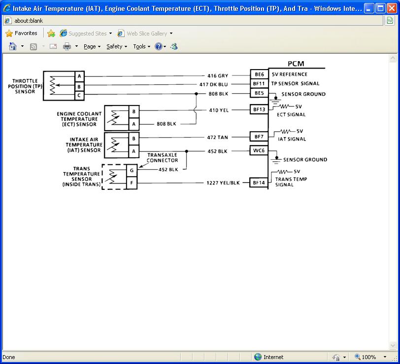
I would agree you have a bad coolant temp sensor or the wire going from the computer to the sensor or the connector itself.There are two sensors one for the gauge and one the computer.I posted a trouble tree for the code's which includes how you can test the sensor with a multimeter.Also see below the code description i posted.I also posted a wire diagram and which sensor is which and where there located.Let me know what you find.


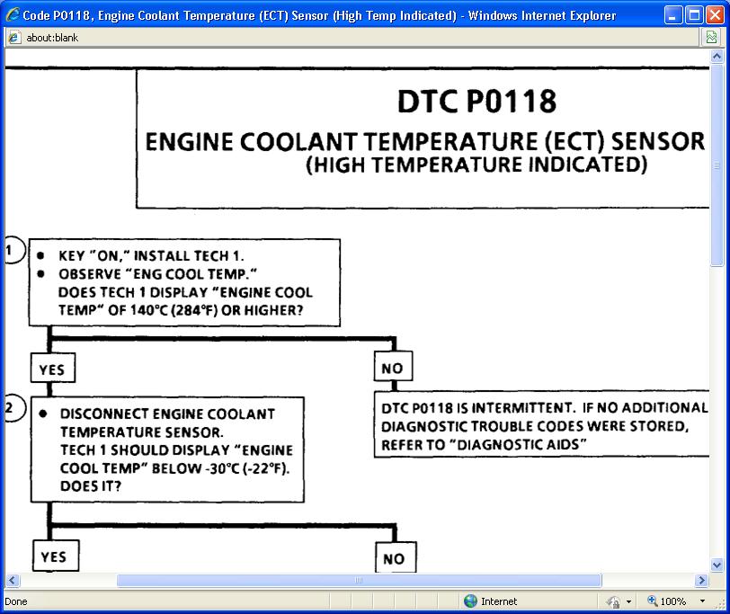
Code P0118, Engine Coolant Temperature (ECT) Sensor (High Temp Indicated)


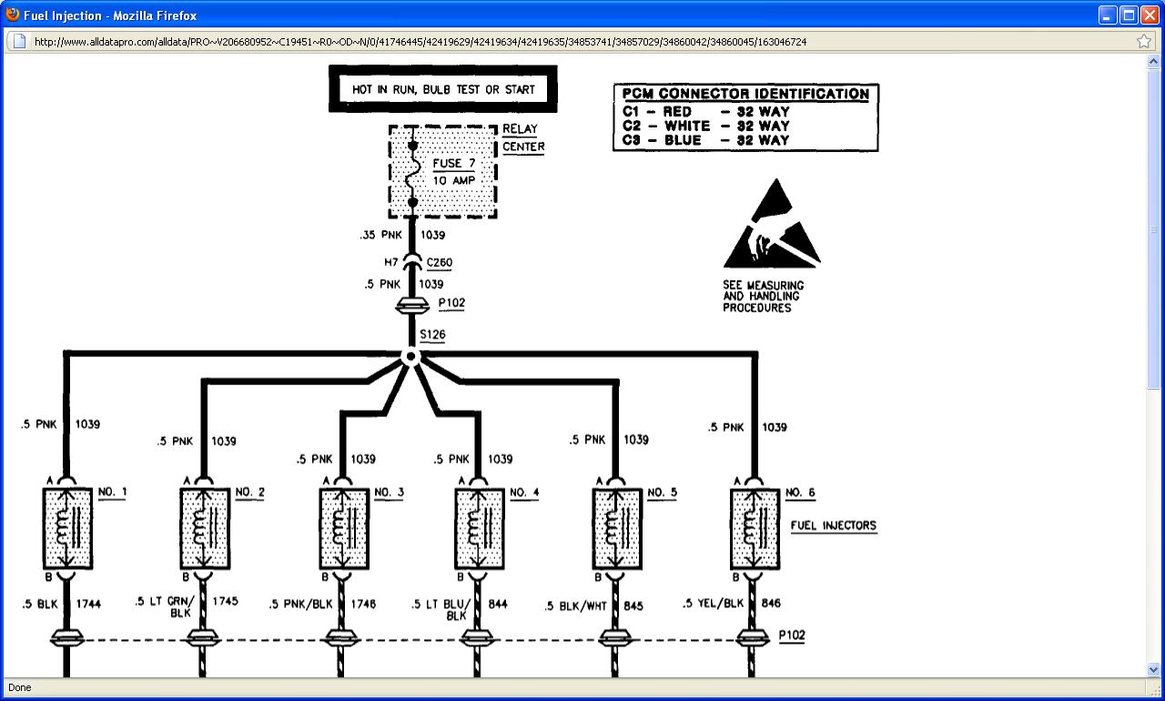
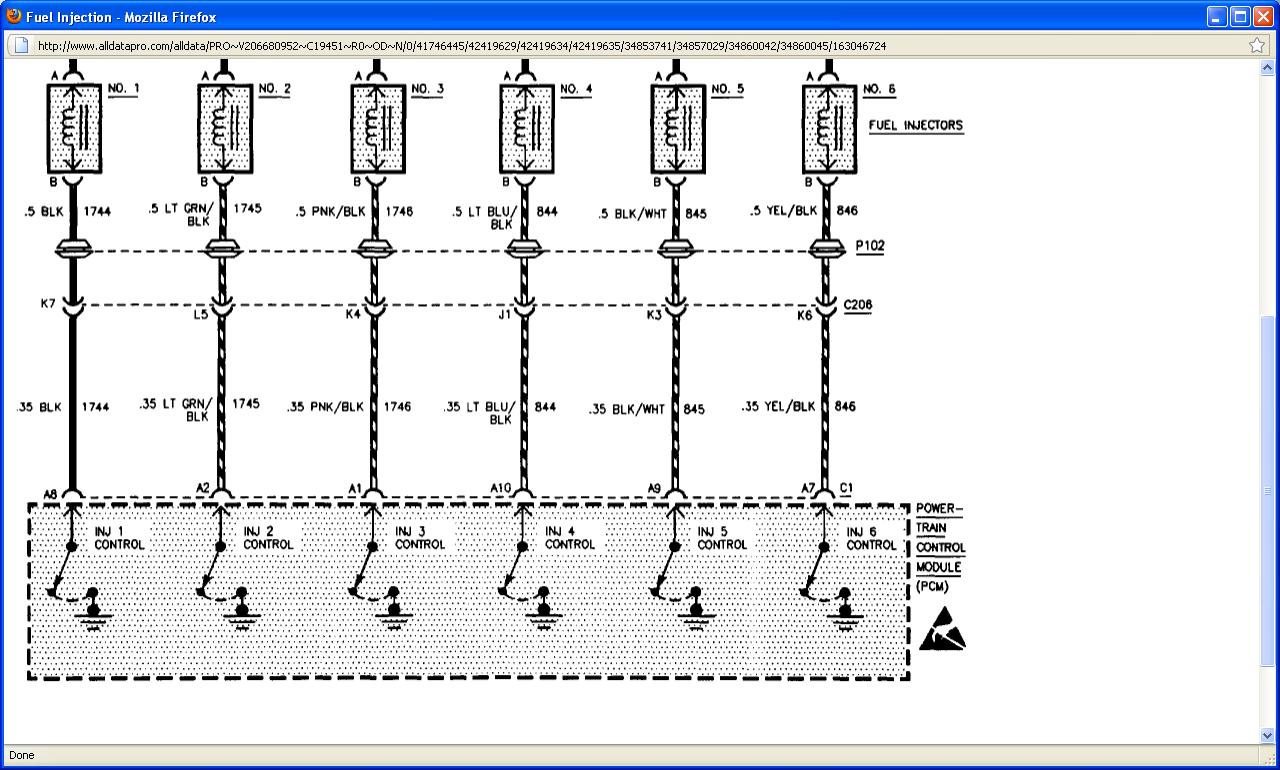
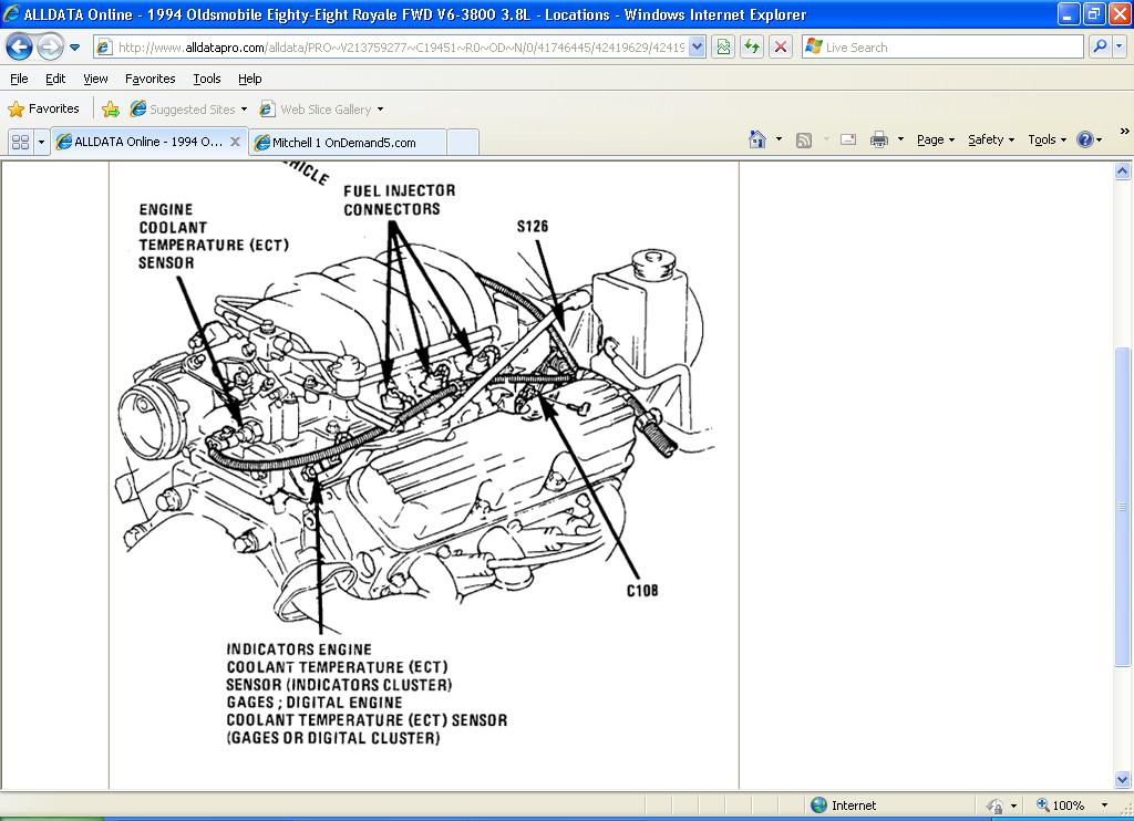
Intake Air Temperature (IAT), Engine Coolant Temperature (ECT), Throttle Position (TP), And Trans Temperature Sensors Wiring Schematic


CIRCUIT DESCRIPTION
The Engine Coolant Temperature (ECT) sensor uses a thermistor to vary the signal voltage from the PCM. The PCM applies a voltage on CKT 410 to the sensor. When the engine is cold the sensor (thermistor) resistance is high; therefore, the PCM will see high signal voltage. As the engine warms, the sensor resistance becomes less and the voltage drops. At normal engine operating temperature (85°C to 95°C), the ECT signal will measure about 1.5 to 2.0 volts.

DTC P0118 WILL SET WHEN:


Engine run time is greater than 15 seconds.
Signal voltage indicates engine coolant temperature above 140°C (284°F) for .4 second.
ACTION TAKEN (PCM will default to):
With a current DTC P0118 set, the PCM will turn the high speed cooling fans "ON" and use a default engine coolant temperature value based on run time. The default value will rise to a maximum value of 90°C (194°F). The PCM will illuminate the MIL (Service Engine Soon).

TEST DESCRIPTION
Number(s) below refer to circled number(s) on the diagnostic chart.


Determines if conditions necessary to set DTC P0118 exist.
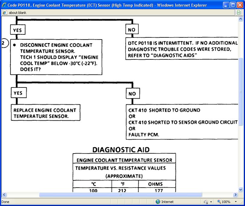
This test will determine if CKT 410 is shorted to ground which will cause the conditions for DTC PO118.
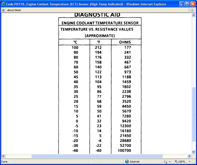
DIAGNOSTIC AIDS
Tech 1 displays engine coolant temperature in degrees. After engine is started, the temperature should rise steadily to about 90°C (194°F) then stabilize when thermostat opens.

An intermittent may be caused by rubbed through wire insulation.

Check for:


CKT 410 for a short to ground.
Intermittent test - With Tech 1, monitor engine coolant temperature while moving related connectors and wiring harness. If the failure is induced, the "engine coolant temperature" display will change. This may help to isolate the location of the malfunction.
Shifted sensor - The "Temperature To Resistance Value" scale may be used to test the engine coolant temperature sensor at various temperature levels to evaluate the possibility of a "shifted" (mis-scaled) sensor, which may result in driveability complaints.

Apr 11, 2011 at 8:51 PM
Avatar
TOBYJAY
  • MEMBER
  • 22 POSTS
Thanks for all the info. The details and amount of information is truly impressive! Your diagram shows two different temperature sensors. Am I correct that the uppermost one near the pulley wheel is the one for the computer?
Apr 11, 2011 at 10:51 PM
Avatar
SATURNTECH9
  • CERTIFIED EXPERT
  • 30,869 POSTS
Your welcome that's the throttle body and yes its the one by the throttle body that you want.Let me know what you find.
Apr 11, 2011 at 10:55 PM
Avatar
TOBYJAY
  • MEMBER
  • 22 POSTS
I believe I've found the sensor that's for the guage cluster but not the sensor for the computer. Any chance you have another view of the location of this sensor? There are various assemblies, cables, etc. in the area shown in your diagram and they may be in the way of what I'm looking for.
Apr 12, 2011 at 8:29 PM
Avatar
SATURNTECH9
  • CERTIFIED EXPERT
  • 30,869 POSTS
Does the sensor you found have a yellow wire and a black wire going to it?The sensor you want is by the throttle body.
Apr 12, 2011 at 8:39 PM
Avatar
TOBYJAY
  • MEMBER
  • 22 POSTS
the sensor I found is to the right of the throttle body and has a single green wire going to it. I do see a cable with a yellow and a black pair going under the throttle body but I can't feel or see where it ends at a sensor because throttle body etc. is in the way. Will I need to disassemble the brackets, etc. of the throttle body to get at this?
Apr 12, 2011 at 9:10 PM
Avatar
SATURNTECH9
  • CERTIFIED EXPERT
  • 30,869 POSTS
The one with the single green wire sounds like the sensor for the temp gauge.Try unplugging it when the temp gauge is reading then see if the temp gauge drops.In the diagram it shows the sensor you want in plain view iam trying to find more info on it.The older cars there is less info available to me.Also my computer is giving me trouble so please bear with me.
Apr 12, 2011 at 9:58 PM
Avatar
TOBYJAY
  • MEMBER
  • 22 POSTS
I finally found the computer coolant sensor located directly under the throttle body. I can't reach far enough to remove the plug on top. I also discovered that if I turn on the ignition without starting the engine, even with the car totally cold, the two supplemental electric fans behind the radiator come on and run indefinitely even though the vehicle is cold. Seems to me this is further proof of a bad sensor telling the ECM that the temperature is high even when the coolant is cold. I'm told that the only way to reach this sensor is to partially remove or loosen the throttle body. Rather than risk damage to the housing or the gasket, I'm thinking it would be best to let my local mechanic do this. Do you agree with my take on the electric fans and the sensor ?
Apr 15, 2011 at 3:30 AM