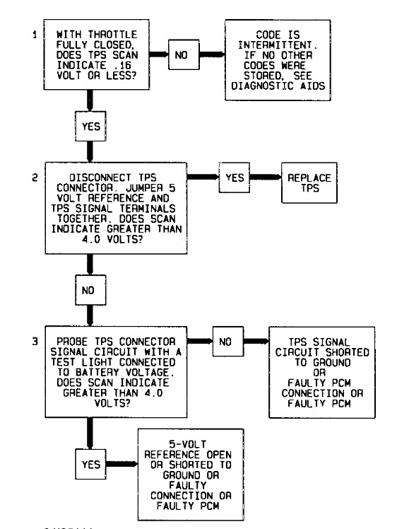
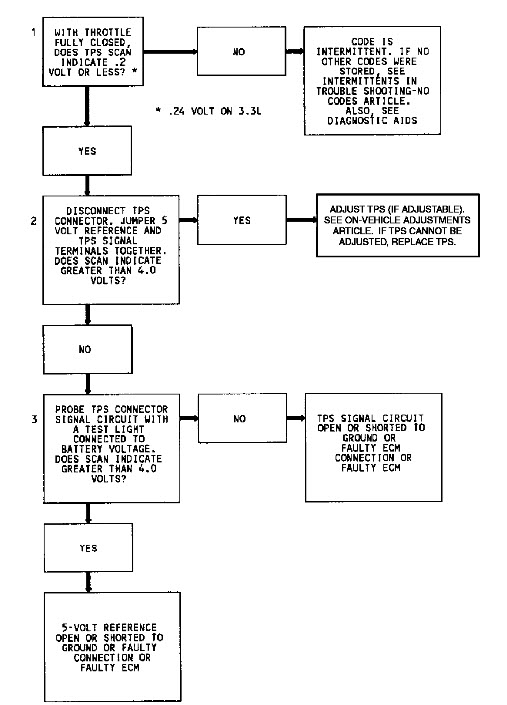
NOTE: Test numbers refer to numbers on diagnostic chart.
1. This test checks if code is result of a hard failure or an intermittent condition.
2. This test simulates conditions for setting code. If control module recognizes change of state, control module and wiring are okay.
3. This simulates a high signal voltage to check for an open in TPS signal line to control module. Scan tester should recognize this signal and display high TPS voltage.
Diagnostic Aids
A scan tester displays throttle position in volts. Closed throttle voltage should be low. Voltage should increase gradually to about 4.5 volts at a steady rate as throttle angle is increased. If code is intermittent, see
INTERMITTENTS in TESTS W/O CODES article in this section.
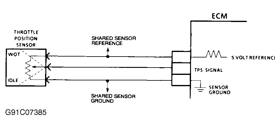
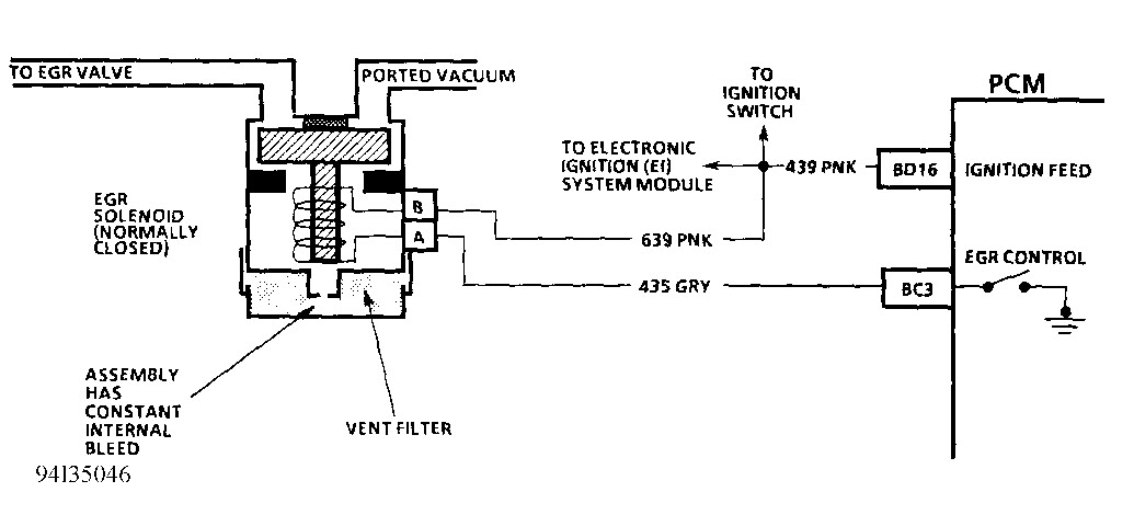
CODE 22 PCM TERMINAL & CIRCUIT WIRING IDENTIFICATION
Application PCM Terminal Wire Color
TPS Signal PB7 Dark Blue
TPS Ground PB2 Black ?
TPS Reference PA3 Gray ?
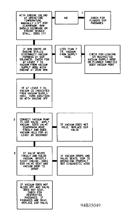
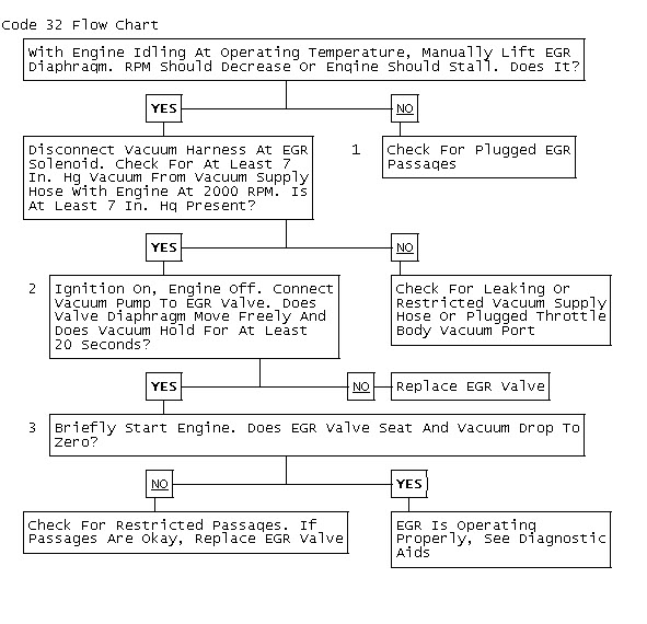
egr tests in charts
Images (Click to enlarge)
Oct 9, 2012 at 3:38 PM