Cylinder Head Removal
Disconnect battery ground cable, then drain coolant from radiator and engine block.
On turbo models, remove turbocharger assembly. On carbureted models, remove air cleaner. On fuel injected models less turbo, disconnect air cleaner hose from air cleaner.
Disconnect exhaust pipe from exhaust manifold.
Disconnect all electrical connectors, fuel lines, vacuum, emission and heater hoses from intake manifold, carburetor (if equipped) and cylinder head. On carbureted models, remove fuel pump.
Remove oil dipstick, distributor, spark plugs and radiator inlet hose, then disconnect heater water inlet hose from heater water inlet pipe.
Disconnect cruise control actuator (if equipped), accelerator cable and engine ground strap from cylinder head. Disconnect throttle cable, if equipped, from cylinder head.
Remove EGR vacuum modulator and bracket from cylinder head (if equipped).
On fuel injected models, remove bolts, air intake chamber and throttle body.
On fuel injected models, remove pulsation damper and disconnect fuel hose from fuel line.
On fuel injected models, disconnect air bypass hose from air valve and remove air valve from intake manifold.
On fuel injected models, remove auxiliary air valve.
On fuel injected turbo models, disconnect oil cooler hose from intake manifold.
On vehicles equipped with power steering, remove drive belt, bolts and pulley. Remove power steering pump mounting bolts and position pump aside. Do not disconnect power steering pump hoses.
Remove ground strap and cylinder head cover.
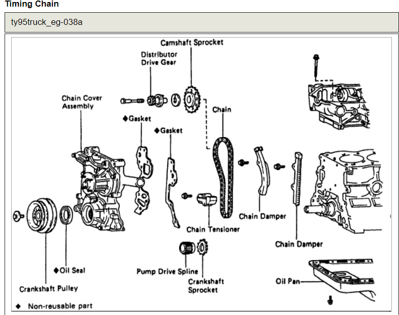
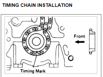
Rotate crankshaft until No. 1 cylinder is set at TDC compression stroke. Place reference marks on timing chain and camshaft sprocket.
Remove semi-circular plug, camshaft sprocket bolt and distributor drive gear and fuel pump drive cam on carbureted models, or distributor drive gear and thrust plate on fuel injected models.
Remove camshaft sprocket and timing chain from camshaft, leaving lower part of chain engaged on lower sprocket. Remove timing chain cover bolt from front inside of cylinder head. The timing chain cover bolt must be removed prior to removing head bolts.
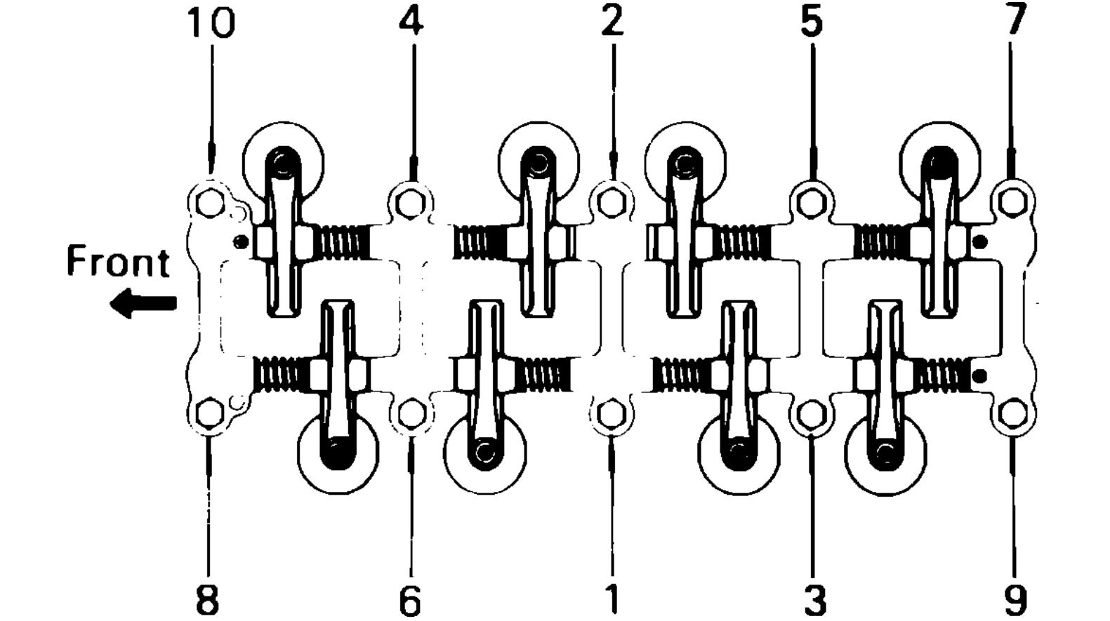
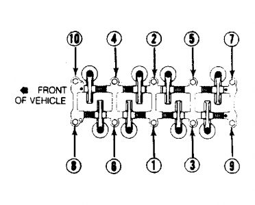
Fig. 45 Cylinder head bolt removal sequence. 22R, 22R-E & 22R-TE engines
Gradually loosen and remove cylinder head bolts in two or three steps as shown in Fig. 45.
Remove rocker arm assembly from cylinder head, then remove cylinder head. If rocker arm assembly is difficult to remove, a pry bar can be inserted at the front or rear of rocker arm assembly to aid in separation.
Remove intake manifold.
Remove EGR valve and exhaust manifold, if not previously removed.
Remove engine hangers, ground straps and cylinder head rear cover.
Fig. 3 Measuring camshaft thrust clearance on overhead cam engine. Typical
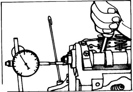
Using suitable dial indicator positioned at front of cylinder head, measure camshaft thrust clearance, Fig. 3. Standard camshaft thrust clearance is .0031-.0071 inch, with a maximum clearance of .0098 inch. If measurement exceeds maximum clearance, replace cylinder head.
Remove camshaft bearing cap bolts, then the bearing caps and camshaft.
Cylinder Head Installation
Install camshaft in cylinder head, then install bearing caps in numbered order from the front of the cylinder head with arrows facing forward. Install bearing cap bolts and torque to 14 ft. lbs.
Rotate camshaft to position alignment pin away from cylinder head.
Install cylinder head rear cover, engine hangers and ground straps.
Install intake manifold, EGR valve and exhaust manifold.
Apply a suitable sealer to where timing cover and front of engine block intersect, then install a new cylinder head gasket.
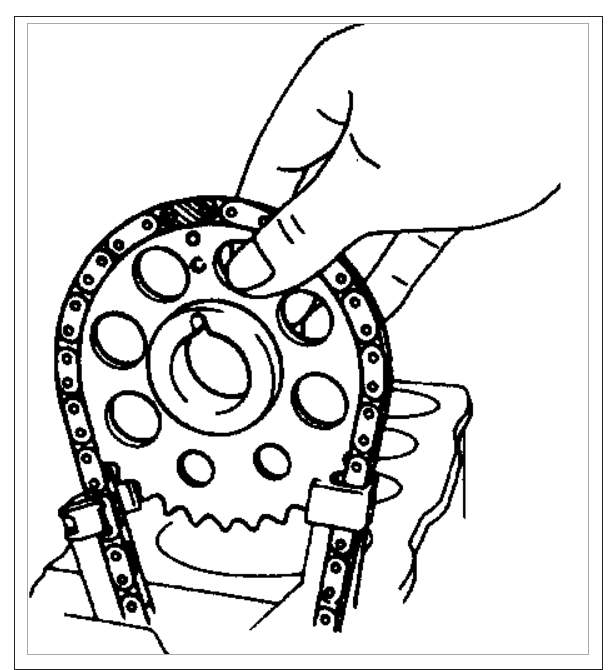
If camshaft sprocket was removed from timing chain, position sprocket in chain while aligning reference marks made during Removal. Install cylinder head onto engine block.
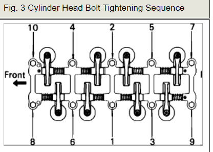
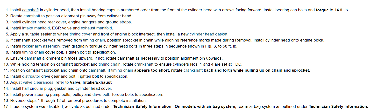
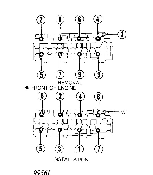
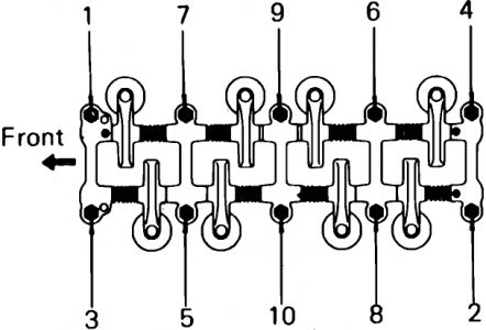
Fig. 46 Cylinder head bolt tightening sequence. 22R, 22R-E & 22R-TE engines
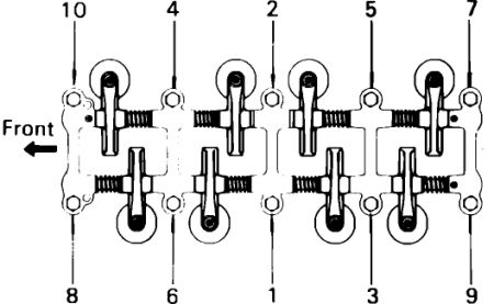
Install rocker arm assembly, then gradually torque cylinder head bolts in three steps in sequence shown in Fig. 46 to 58 ft. lbs.
Install timing chain cover bolt. Torque bolt to 9 ft. lbs.
Ensure camshaft alignment pin faces upward. If not, rotate camshaft as necessary to position alignment pin upwards.
While holding tension on camshaft sprocket and timing chain, rotate crankshaft to ensure cylinders Nos. 1 and 4 are set at TDC.
Position camshaft sprocket and chain onto camshaft. If timing chain appears too short, rotate crankshaft back and forth while pulling up on chain and sprocket.
Install distributor drive gear and bolt. Torque bolt to 58 ft. lbs.
Adjust valve clearances, refer to ``Valves, Adjust'' for procedure.
Install half circular plug, gasket and cylinder head cover.
Install power steering pump bolts, pulley and drive belt. Torque bolts 33 ft. lbs.
Reverse steps 1 through 12 of removal procedures to complete installation.
https://www.2carpros.com/kpages/auto_repair_manuals_alldata.htm
Apr 1, 2019 at 5:49 PM
(Merged)


 Here are more diagrams below to help you do the job.
Check out the diagrams (Below)
Please let us know if you need anything else to get the problem fixed.
Cheers
Here are more diagrams below to help you do the job.
Check out the diagrams (Below)
Please let us know if you need anything else to get the problem fixed.
Cheers