by pass volt reg install old style?

1991 DODGE DAKOTA
164,000 MILES
Avatar
HUEY777
  • MEMBER
  • 28 POSTS
1991 dakota how to by pass volt reg and install old style ford reg wich wires to cut etc. and i know its been done so do any of u pros know how
Mar 22, 2012 at 5:51 PM
Advertisement
Avatar
CARADIODOC
  • CERTIFIED EXPERT
  • 34,306 POSTS
A Ford regulator won't work. It's the wrong kind of circuit. You can use the '70s style Chrysler electronic voltage regulator but that's going to leave you with the Check Engine light on.

How did you determine the regulator is bad? That 's a very rare failure.
Mar 22, 2012 at 7:00 PM
Avatar
HUEY777
  • MEMBER
  • 28 POSTS
so far i have replaced alt and bat and took alt back off took to napa had tested tested good ode says open field check light still on and doe not charge
Mar 22, 2012 at 7:34 PM
Advertisement
Avatar
HUEY777
  • MEMBER
  • 28 POSTS
oh i have also took the harness out of truck looked at all of wires and concters been chaseing this for a week all wires good all fuses good
Mar 22, 2012 at 7:37 PM
Avatar
HUEY777
  • MEMBER
  • 28 POSTS
so i can use later style dodge 80s but i need to what wire needs to go were blue to and green
Mar 22, 2012 at 7:40 PM
Avatar
CARADIODOC
  • CERTIFIED EXPERT
  • 34,306 POSTS
There's going to be other problems but an external voltage regulator can be installed. First, since it is such an uncommon problem, lets start with some proper tests. Removing the entire wiring harness is WAY overkill in this circuit.

The engine has to be running to take these voltage measurements. Measure the voltage on all three wires on the back of the alternator. The large output wire bolted on must have full battery voltage all the time, engine on or off. One of the smaller wires must have full battery voltage when the engine is running. If either of those are missing, the voltage regulator isn't the problem. Holler back with those three readings.
Mar 22, 2012 at 8:50 PM
Avatar
HUEY777
  • MEMBER
  • 28 POSTS
did that already other techs on here said check harness
Mar 22, 2012 at 9:27 PM
Avatar
HUEY777
  • MEMBER
  • 28 POSTS
green wire 11.09 blue 11.34 batt 12.04 at bat and back of alt
Mar 22, 2012 at 9:33 PM
Avatar
CARADIODOC
  • CERTIFIED EXPERT
  • 34,306 POSTS
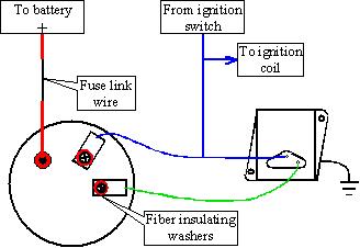
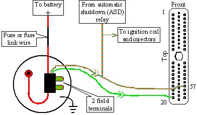
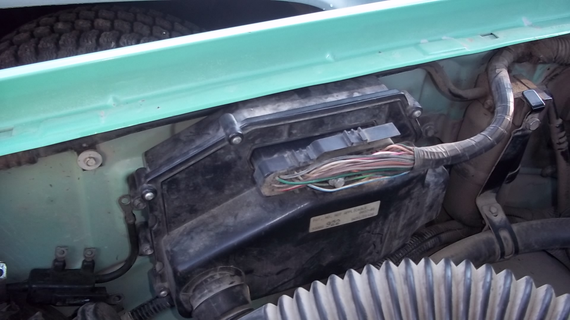
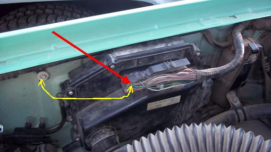
Dandy. Now, with the engine running, . . . woops, wait a minute. I don't have a '91 service manual handy so I'm doing this from memory. Do you have those blue and green wires plugged into the two terminals on the back of the alternator, or do they go into a little black plastic block, then there's two metal tabs bolted to the two terminals with little nuts?

If you have two separate wires, ground the green one while the engine is running, but please do not raise engine speed. If the alternator is indeed okay, which I suspect it is, doing this "full-field" test AND raising engine speed can do a lot of damage. We don't need to make more work.

What you should see with the green wire grounded is the head lights get brighter, voltage, if you're monitoring it, will go up to over 15 volts, and you'll hear the alternator sing and load the engine down. That will prove everything is good to that point.

If you have the little block that the two small wires go through, don't pierce the insulation as that will just be asking for more trouble in a few months. Instead, go here to see which terminal to ground to do the full-field test:

http://randysrepairshop.net/which-field-terminal-do-i-ground.html

If you ground the wrong one, you can burn out a connection in the Engine Computer. I know from my students doing that on a "bugged" Dakota that I built. Again, this only applies if you can't tell which terminal goes to the green wire.

You can also look at this page to see if that sad drawing looks like your two smaller terminals:

http://randysrepairshop.net/interpreting-the-test-results-chrysler-charging-system-1970---1989.html

That is the diagram that will be used if you still want to install the external regulator.

This next page for the newer style systems shows that plastic terminal block I'm talking about, and it explains why you can't tell which wire goes where. That's when you have to go back to that first page I sent you to.

The fact that one small wire has a slightly lower voltage than the other one surprises me because that proves some current is flowing in that circuit, it's just not enough. That green wire should be down to around 4 - 11 volts. That also means there can't be a break in the wire or connector pins, but something like that is adding too much resistance. This is where the full-field test will tell us a lot. If grounding the green wire gets the alternator working, follow it to the next connector and ground it there too. Work your way along that wire all the way to the computer and keep grounding it at every accessible test point. You're looking for the first point where grounding it doesn't make the alternator charge wide-open.
Mar 22, 2012 at 10:21 PM
Avatar
HUEY777
  • MEMBER
  • 28 POSTS
what do i do with the blue and green wires does anyone know how to do this
Mar 23, 2012 at 12:27 AM
Avatar
CARADIODOC
  • CERTIFIED EXPERT
  • 34,306 POSTS
You haven't told us which setup you have, two separate terminals or that plastic block. We aren't going to guess and have you mess something up.

Did you even bother to do the full-field test? If you modify this circuit with the external regulator, what are you planning on doing about the Check Engine light that is going to be on all the time? How will you know when some other problem develops?

If you didn't look at how this circuit is wired on the web page, here's the diagram again. There's a blue and green wire at the alternator and a blue and green wire at the regulator. The regulator has to be grounded to work.
Mar 23, 2012 at 2:24 AM
Avatar
HUEY777
  • MEMBER
  • 28 POSTS
mne has black plastic box alt works took to dodge dealer today they tested it 4 times its good
Mar 23, 2012 at 3:09 AM
Avatar
HUEY777
  • MEMBER
  • 28 POSTS
so to bypass do i go from alt to new reg but do i need to run back into wires that i take off of the back of alt i really need to know how to do it
Mar 23, 2012 at 3:16 AM
Avatar
CARADIODOC
  • CERTIFIED EXPERT
  • 34,306 POSTS
I don't doubt the alternator is fine. It's the wiring that gives more trouble. Here's two drawings of Engine Computer connectors. I can't find a '91 service manual. The closest I have is for a '93, and it shows the big 60-pin connector on the right. I tried to help someone else recently with a '91 Dakota but he said he had the three connectors like on the left drawing. That is for a '96 and '97 model.

I thought a '91 had the computer next to the battery behind the left head light and the big connector. If yours has that type, does it also have a separate 14-pin connector next to it?

If you have the three smaller connectors, the computer will be on the right inner fender halfway between the head light and firewall.
Mar 23, 2012 at 3:28 AM
Avatar
CARADIODOC
  • CERTIFIED EXPERT
  • 34,306 POSTS
Please do these extremely simple things first so I know this is going to work. You are working with by FAR the world's simplest and most reliable charging system ever produced, but if there's a problem in the wiring, this modification still won't work and you're going to be frustrated. I'm going to know what works and what doesn't before you start cobbling this system so it works when you're done, otherwise you'll have to find someone else who knows how to do it.

I need to tell you which wire to cut, but I won't know that until you tell me which computer connector style you have and how many plugs there are. There's three different versions of computer and they all have the green wire in different places. There isn't enough time left in my lifetime to type descriptions for all the possibilities, plus that would just add unnecessary confusion to the story.
Mar 23, 2012 at 3:42 AM
Avatar
HUEY777
  • MEMBER
  • 28 POSTS
ok cool my is has the harness go from the alt down to the firewall on rightside to a connecter from thier to computer on the right side inner fender also this is running the nesso 90 amp alt if that helps
Mar 23, 2012 at 4:34 AM
Avatar
HUEY777
  • MEMBER
  • 28 POSTS
is any way for me to test the wires as i have looked at the wires can i unhook computer and put power to green wire and check it like that or how do suggest i check wires i just want to get this fixed if i can so i will try anything
Mar 23, 2012 at 4:59 AM
Avatar
CARADIODOC
  • CERTIFIED EXPERT
  • 34,306 POSTS
Assuming you have those three smaller connectors, look on the bottom row of pins in the middle connector and see if the green wire is the second one from the end. If it is, see if you can slide a stretched out paper clip in alongside that wire. I can't remember if there's a cover over the wires. Don't take those connectors apart. They're REAL frustrating to put back together.

If you can't slide a paper clip in there, (it has to touch the terminal), you can resort to pushing a razor blade through the wire's insulation until it touches the wire. Now, with the engine running and the head lights on, use a piece of wire or small jumper wire to ground that green wire. Tell me what happens to the head lights when you do that.
Mar 23, 2012 at 5:25 AM
Avatar
CARADIODOC
  • CERTIFIED EXPERT
  • 34,306 POSTS
No, power doesn't go to that wire. I just told you what to do, but for some reason your replies aren't showing up until after I post mine. Maybe we're both typing at the same time.

You have to ground that green wire. I want to be sure you have the right wire before you cut it, and only IF you have to cut it. You do not have to disconnect it to ground it. Just use a piece of wire to touch that terminal with one end and the body or engine with the other end. This is a real fast simple test that should take all of five seconds but the information it provides is important.
Mar 23, 2012 at 6:19 AM
Avatar
HUEY777
  • MEMBER
  • 28 POSTS
here are pics of my computer hareness runs to the frist block looking connecter then to computer hope this makes it easyer to tell witch i have
Mar 23, 2012 at 4:50 PM
Avatar
CARADIODOC
  • CERTIFIED EXPERT
  • 34,306 POSTS
That's the 60-pin plug I thought should have been on your truck. The red arrow is pointing to that green wire in pin 20. Poke a paper clip in next to it so it touches the terminal, then use a piece of wire to ground it as shown with the yellow double arrow. (Put the wires back on the alternator and have the engine running when you do that). That five-second test will tell us how to proceed. Have the head lights on too. I need to know what happens when you ground that wire.
Mar 23, 2012 at 5:07 PM
Avatar
HUEY777
  • MEMBER
  • 28 POSTS
kills truck makes it die
Mar 23, 2012 at 5:32 PM
Avatar
CARADIODOC
  • CERTIFIED EXPERT
  • 34,306 POSTS
Did you have the battery disconnected when you took the wires off the alternator? If you did, the Engine Computer "lost its mind" and has to have "minimum throttle" relearned before it will know when it must be in control of idle speed. To meet the conditions for the relearn to take place, (start with a charged up battery), drive it at highway speed with the engine warmed up, then coast for at least seven seconds without touching the pedals. You'll likely have to keep one foot on the gas pedal to keep it running until that relearn takes place. That seven-second coast is similar to coasting off an exit ramp, but you can do it anywhere on any highway.

A working alternator will load the engine down quite a bit and that's probably why the engine stalled. The only two things left then are the voltage regulator is dead or that terminal for the green wire in the plug is stretched or corroded. A defective regulator is the more likely of the two. By grounding that green wire at the plug, with that one test you just proved the wiring is okay for the entire rest of the circuit and the alternator is okay too. If you want to be 100 percent sure the system works, do that test again after relearning minimum throttle so the engine will stay running. Then you can see what the proper full-field test does when you ground that wire. This is a standard, very quick test done to determine whether a charging problem is the fault of the regulator or something else. I explain the procedure for Fords, GMs, and Chryslers on my web site.

The first step is to mount the new voltage regulator to the body, near the computer. The housing has to make good contact to ground it so it can't be insulated by paint or rust. If you get the regulator from a salvage yard, get the plug too with a bunch of wire. You'll see the plug has a blue and green wire. Those go to the two small terminals on the back of the alternator. Probably the best idea, to keep from butchering the original wiring, is to simply leave the black plastic block and terminals off completely for now. Leave the fat output wire bolted on. For the time being, just run the two wires from the regulator to the two small studs on the alternator. The system won't work yet because we need to connect the blue wire from the truck's harness for the power source, but I think there's an easy way to do that which doesn't involve running more wires.

To figure out which wire that is, measure the voltages on the two wires shown with arrows. First do that with the ignition switch in the "run" position but the engine off. If both terminals have 0 volts, measure them again with the engine running. One will have full battery voltage and the other one should have 0 volts. Tell me which one, by arrow color, has the voltage. Also tell me if you had to have the engine running or not to get that voltage.
Mar 23, 2012 at 6:14 PM
Avatar
HUEY777
  • MEMBER
  • 28 POSTS
red arrow which on the alt is lower of the two small wires
Mar 23, 2012 at 9:28 PM
Avatar
HUEY777
  • MEMBER
  • 28 POSTS
also ran and got a new vr1 reg and had search the junkyard for harness have reg mounted on fender well now
Mar 23, 2012 at 9:32 PM
Avatar
CARADIODOC
  • CERTIFIED EXPERT
  • 34,306 POSTS
There's a green and blue wire in the plug for the regulator. Those two wires go to the two small terminals on the alternator. Either wire can go to either terminal, BUT, . . . for convenience, to power the system, see if you can bolt on only the one terminal in the plastic block that has the red arrow. That terminal must go to whichever stud you hook the blue wire to.

Did you have to run the engine to have 12 volts on that terminal?
Mar 23, 2012 at 9:50 PM
Avatar
HUEY777
  • MEMBER
  • 28 POSTS
just trun on ignition switch on
Mar 23, 2012 at 10:41 PM
Avatar
HUEY777
  • MEMBER
  • 28 POSTS
hooked up just like you told me to but i had cut the little conecter on the green side of existing harness but now my truck is up and running everthing works and it charges thank you very much
Mar 23, 2012 at 11:51 PM
Avatar
CARADIODOC
  • CERTIFIED EXPERT
  • 34,306 POSTS
What do you have for battery voltage with the engine running? It should be between 13.75 and 14.75 volts. It might be a little low but slowly rising if the battery is run down.

Any splices you might have made in the wires should be soldered, then sealed with heat-shrink tubing. Electrical tape will let moisture in, and it will unravel from the heat under the hood. They make that tubing now with hot-melt glue inside to really seal out the moisture.
Mar 24, 2012 at 12:28 AM