Dodge Dynasty charging system trouble

1990 DODGE DYNASTY
193,550 MILES • 6 CYL • FWD • AUTOMATIC
Avatar
RANGER812572
  • MEMBER
  • 52 POSTS
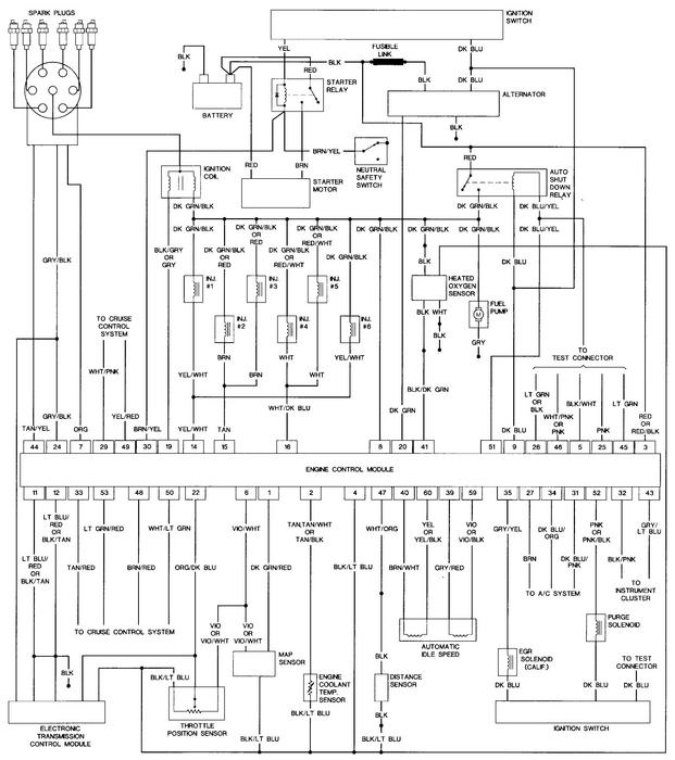
I have a 1990 Dodge Dynasty Base 3.0L v6. I am getting DTC 41. Open or short detected in generator field circuit. I had a mechanic originally try to figure out why my voltage was fluctuating so much when I used my turn signals. It wasn't a big deal at the time. He tried to test voltage output at the alternator and suddenly I had about only 12 volts or less coming out of the alternator. I did have 13.6 or better. I have replaced the alternator and also now the pcm (used parts on both) no difference. I am stumped.
Mar 9, 2011 at 12:27 AM
Advertisement
Avatar
CARADIODOC
  • CERTIFIED EXPERT
  • 34,306 POSTS
Measure the voltage on the two small terminals on the back of the alternator while the engine is running. Then we'll know where to go next.
Mar 9, 2011 at 12:52 AM
Avatar
RANGER812572
  • MEMBER
  • 52 POSTS
I measured the voltage on those two small terminals, and there was no noticeable voltage there. Keep in mind I was using a multimeter with an analog needle (not a digital readout), but it didn't move a bit. Im getting approximately 12.3 now on at the battery with the engine running.
Mar 9, 2011 at 1:33 AM
Advertisement
Avatar
CARADIODOC
  • CERTIFIED EXPERT
  • 34,306 POSTS
Dandy. I always second guess myself but if you truly have no voltage there, this is going to be a quick fix. By the way, you DID have the engine running when you took the readings, right? There is supposed to be 0 volts on both terminals when the engine is not rotating, (cranking or running).


The ignition coil, injectors, oxygen sensor heaters, fuel pump relay, and alternator field are all powered from the automatic shutdown (ASD) relay. The fact the engine runs means all of those things are working, except the alternator. That only leaves the piece of wire from the splice to the alternator.


I only have a '92 service manual but the circuit should be the same. Look for a black ten-pin connector behind the battery. There will be a dark green / orange wire in one of the corners. Back-probe those terminals to see if voltage is there on both sides. The splice for all the other stuff is before that connector, so if there's a bad connection there, it will only affect the alternator.
Mar 9, 2011 at 3:30 AM
Avatar
RANGER812572
  • MEMBER
  • 52 POSTS
Yes, the engine was running at the time. And if what you say is the case, how do I fix it?
Mar 9, 2011 at 3:43 AM
Avatar
CARADIODOC
  • CERTIFIED EXPERT
  • 34,306 POSTS
Look for that connector and see if there is voltage on either or both sides of it.
Mar 9, 2011 at 3:49 AM
Avatar
RANGER812572
  • MEMBER
  • 52 POSTS
Okay, I found two ten pin connectors behind the battery. I looked for the dark green wires and tested voltage on both sides with the engine running. Both sides on all green wires had the same voltage on both sides. I also found an orange wire on the other connector, tested voltage on both sides and the same voltage on both sides.
Mar 9, 2011 at 7:25 AM
Avatar
CARADIODOC
  • CERTIFIED EXPERT
  • 34,306 POSTS
If you have 12 volts on both sides of the connector but not on either terminal on the alternator, there is a break in that wire between the two. There should be no splices to corrode in the harness. Look near the black plastic terminal block on the alternator where the wires come into it to see if someone poked a hole through the insulation to take a reading. I forbade my students from doing that because moisture will get in there and corrode the wire.
Mar 9, 2011 at 3:09 PM
Avatar
RANGER812572
  • MEMBER
  • 52 POSTS
When I tested voltages last night, I must have done something wrong. I followed the Dark Green and Blue/white wires from the alternator all the way back to the computer. I checked continuity on the wires all the way from the computer to the alternator (engine off). I had continuity. I started the car, and checked power all along the wires starting at the alternator. I didn't find any voltage coming thru anywhere.
Mar 9, 2011 at 10:51 PM
Avatar
CARADIODOC
  • CERTIFIED EXPERT
  • 34,306 POSTS
If by "anywhere" you mean including at the connector, there has to be a break in the dark green / orange wire before the connector. You can prove that by using a jumper wire from the battery positive post and a paper clip stuck in beside the terminal in the connector to apply battery voltage to that wire. If the head lights get brighter or you hear the engine load down slightly you'll know the alternator is working and everything after that point is okay.
Mar 9, 2011 at 11:00 PM
Avatar
RANGER812572
  • MEMBER
  • 52 POSTS
I ran a jumper wire from the battery to the alternator. No noticeable change in either engine load or headlight brightness. I'm just about ready to take and run a new wire from the computer to the alternator directly. No plugs or anything. On my car its just a dark green wire. There is no orange stripe.
Mar 9, 2011 at 11:35 PM
Avatar
CARADIODOC
  • CERTIFIED EXPERT
  • 34,306 POSTS
What'cha got in the other corner of the plug? The green wire with no stripe always goes from the alternator to the voltage regulator in the computer. It's the other one that is the 12 volt feed and appears to be missing on your car. Remember, I'm using a '92 service manual. Look at the black plastic terminal block on the back of the alternator where the wires go into. You'll see the dark green one. If the other one doesn't have an orange stripe, it should have a black one that is almost impossible to see. You should find a matching wire in the connector. My students used to make a lot of mistakes when troubleshooting my "bugged" cars when their paper clip probes didn't make good contact with the terminals in the connectors. Voltmeter probes give less trouble because they are stiff enough to wiggle around until they touch the terminal. Just don't get too carried away so the tip breaks off.
Mar 10, 2011 at 12:10 AM
Avatar
RANGER812572
  • MEMBER
  • 52 POSTS
The black plastic block at the back of the alternator has a blue wire with a white stripe, and a green wire. I was using a volt meter lead as a jumper wire. I got connection on both ends, but nothing changed. The other wires coming away from there are the two thicker wires. Both black one with a white stripe.
Mar 10, 2011 at 12:33 AM
Avatar
CARADIODOC
  • CERTIFIED EXPERT
  • 34,306 POSTS
Okay, to stop this guessing game, I marched my fanny through ten foot snow drifts out to my shop and back, up hill, . . . both ways! to find a closer service manual. I came up with an '89 book which is considerably different than the '92 book I was using. Do you indeed have that 10-pin plug or do you have a 6-pin plug like shown here? This one shows a dark blue wire which is what Chrysler used for 12 volt feeds for decades but there's no white stripe. They still show the dark green wire going to the regulator which is consistent all the way back to 1970 models.
Mar 10, 2011 at 1:44 AM
Avatar
RANGER812572
  • MEMBER
  • 52 POSTS
I have a 10 pin plug. Sorry bout you having to walk thru a bunch of snow, but up hill both ways? You must have been barefoot... The blue/white wire from the alternator (same gauge as the green)connects into a different plug (next to the plug the green wire is in). I will have to look again to see if the other green wire in the plug has an orange stripe.
Mar 10, 2011 at 2:05 AM
Avatar
RANGER812572
  • MEMBER
  • 52 POSTS
I checked that other green wire in the plug. It is a green with a black stripe.
Mar 10, 2011 at 2:54 AM
Avatar
CARADIODOC
  • CERTIFIED EXPERT
  • 34,306 POSTS
Darn the bad luck. Let's back up a minute and recheck the voltages on the two small terminals on the alternator with the engine running. If you'd prefer to troubleshoot this without having to run the engine, locate the automatic shutdown (ASD) relay and bypass the contacts. I can tell you how to do that if you tell me if you have three relays bolted to the left inner fender or if you have a fuse box under the hood with square relays in it. Otherwise just run the engine.
Mar 10, 2011 at 3:01 AM
Avatar
RANGER812572
  • MEMBER
  • 52 POSTS
Its dark out now, I will recheck the voltages at the alternator tomorrow. But i'm pretty sure there will be zero voltage at the two smaller terminals. If it matters, I have a fuse box under the hood with the relays in it.
Mar 10, 2011 at 3:11 AM
Avatar
CARADIODOC
  • CERTIFIED EXPERT
  • 34,306 POSTS
If you want to bypass the ASD relay, jump terminals 30 and 87 in the socket with a stretched out paper clip. You won't even need the ignition switch turned on. This way you can lean over the alternator without your tie getting caught in the belt.
Mar 10, 2011 at 3:17 AM
Avatar
RANGER812572
  • MEMBER
  • 52 POSTS
Measured with the engine running, using the battery negative as my ground, I checked the voltage at both small terminals. I didn't get any voltage out of either of them.
Mar 10, 2011 at 11:01 PM
Avatar
RANGER812572
  • MEMBER
  • 52 POSTS
The wiring diagrams I have seen show a fusible link off the ground wire. If that was bad, could it cause my problem? Also, is that black plastic box at the back of the alternator a fusible link or no?
Mar 11, 2011 at 12:00 AM
Avatar
CARADIODOC
  • CERTIFIED EXPERT
  • 34,306 POSTS
OK. There has to be a break in the feed wire. Turn the engine off, then use your ohm meter to measure continuity from either terminal to the feed wire on the ignition coil. I think you said you found that to be a blue/ white wire. My book for a '92 model shows dark green / orange, but it doesn't matter. Both are on the same circuit. Measure from each of the alternator terminals. There should only be a few ohms difference but it is very common to find an open circuit between the two brushes when the field winding isn't spinning due to little chips of carbon getting stuck under a brush. Irritating the drive belt sometimes cause the brushes to make a better contact. Those brushes can lead to false reading and confusion; that's why it's just safer to measure from both terminals since we can't tell which one goes to which wire. The proper finding is very low resistance, in the area of only a few ohms, (the same as when you touch the meter leads together). If you find an open circuit between the coil and alternator, that would confirm why there is no voltage on the alternator.
Mar 11, 2011 at 12:10 AM
Avatar
CARADIODOC
  • CERTIFIED EXPERT
  • 34,306 POSTS
I've never seen a fuse link in a ground wire. There are other ground wires between the battery and left fender and between the engine and firewall but a lot of other stuff would be affected if they were bad. That black block is just a way to keep the wires together for quicker assembly. I never cut one open but if there is anything in there, it would be a small coil and capacitor to reduce the whine that could be picked up by the antenna and heard on AM radio.
Mar 11, 2011 at 12:18 AM
Avatar
RANGER812572
  • MEMBER
  • 52 POSTS
I will measure it tomorrow, its dark outside. I am attaching a copy of the wiring schematic I found on a Chilton's website. Maybe this will help you out bit.
Mar 11, 2011 at 3:13 AM
Avatar
CARADIODOC
  • CERTIFIED EXPERT
  • 34,306 POSTS
This is a lot easier to follow than the Chrysler diagrams but they don't show the connectors. I circled the wire that has to be broken. It should pass through that 10-pin connector too behind the battery. The splice right above my circle could also be suspect but the other blue wire has to be good between the ignition switch and ASD relay otherwise the engine wouldn't run. One thing I must correct, . . . this is the older circuit that does NOT require the engine to be running to take voltage readings in the alternator circuit. The blue wire will have 12 volts whenever the ignition switch is on. The automatic shutdown relay still runs the fuel pump, injector, and ignition coil, but not the alternator. That means everything I told you about bypassing the relay wouldn't have worked anyhow. All you have to do is to have the ignition switch in the "run" position but the engine doesn't have to be running. Also, disregard my comment in my last post about measuring continuity in that blue wire. Those two points are on different sides of the ASD relay.
Mar 11, 2011 at 4:08 AM
Avatar
RANGER812572
  • MEMBER
  • 52 POSTS
Thanks, I'll check it out tomorrow.
Mar 11, 2011 at 4:36 AM
Avatar
RANGER812572
  • MEMBER
  • 52 POSTS
Well, the problem is fixed now. Thank you for all your help. The problem turned out to be this nifty little fuse in the under hood fuse block labeled IGN Run. To me, that description means the car won't run without that fuse. I checked the fuse ( of all the dumb things) and it turns out it was bad. I replaced the fuse and the car works great now. Thank you for all your help, and you telling me the ignition wire was the problem helped lead me to the problem.
Mar 12, 2011 at 1:21 AM
Avatar
CARADIODOC
  • CERTIFIED EXPERT
  • 34,306 POSTS
That should have affected the ignition coil and injectors but there's no arguing with success. Happy to hear it's working.
Mar 12, 2011 at 2:12 AM